


1. Introduction
In the research area of electromagnetic compatibility (EMC), the continuous pursuit of higher functionality, improved performance, and reduced production costs has become a dominant trend in the development of modern electrical and electronic systems. However, these advancements are often accompanied by a side effect: an inevitable increase in the level of electromagnetic interference (EMI) that such systems generate. As devices become more compact and operate at higher switching frequencies, the emission spectrum of unwanted noise tends to broaden, posing significant challenges for EMC design. To address these challenges, electromagnetic interference filters have been widely adopted, and among their critical components, the common-mode choke stands out as a fundamental building block. This component plays a decisive role in suppressing common-mode noise, especially in power conversion and switching applications, where power electronic devices typically produce disturbances over a wide frequency band ranging from a few kilohertz to several megahertz [1,2]. In power supply systems, electromagnetic noise can generally be divided into two categories: differential-mode noise and common-mode noise.
Differential-mode noise appears when current flows in opposite directions through the signal line and the return (ground) line. In contrast, common-mode noise propagates along all conductors within the cable in the same direction. To suppress the latter, common-mode choke coils are employed. When common-mode currents pass through the choke, they generate magnetic flux that accumulates inside the ferrite core, enabling the device to function effectively as an inductor and thereby attenuate the unwanted noise. For differential-mode currents, however, the magnetic flux induced in opposing directions tends to cancel out, which means the choke offers little impedance to these currents and issues such as magnetic core saturation remain minimal [3]. In this paper, the different magnetic structures will be clarified. The air gap’s function in E-I core common mode choke will be explained with EMI test phenomenon.
|
Core Shape |
Advantages |
Disadvantages |
|
E cores |
1. Winding structures can be realized with relatively low cost. 2. The generated heat can be dissipated efficiently. 3. Installation is flexible, allowing multiple mounting orientations. 4. Direct mounting onto printed circuit boards (PCBs) is supported. 5. The assembly process is straightforward and convenient.. 6. Core materials are generally inexpensive and easily available.7.Cores are inexpensive. |
1. Shielding is minimal. |
|
Toroid |
1. Minimal radiated magnetic flux. 2. Does not require additional mounting accessories. 3. Core materials with low magnetic loss are available. 4. Air gaps can be introduced to adjust magnetic characteristics. 5. Rounded edges reduce the risk of wire bending stress. 6. Surface coating or painting is possible. 7. Core materials are generally cost-effective. 8. High input impedance is achievable. |
1. Specialized winding equipment is required for toroidal shapes. 2. Susceptible to external stray magnetic fields. 3. Cores may experience saturation under unbalanced excitation conditions. |
2. Comparison of E-I core and toroid core common mode choke
Common mode choke can have many different shapes: toroid, E cores, pot cores, etc. Each structure has its advantage and disadvantage. Shows in Table I [4].
3. Inductance vs. frequency
International Special Committee on Radio Interference is responsible for the EMC requirements with (CISPR22) defining the strictest limit on conducted emissions. These limits (conducted emissions) core described in the product standards EN55022 limits for class B digital devises, in the frequency range of 150Khz to 30Mhz [5].
Power board needs to pass the conductive emission test using Line Impedance Stabilization Network based on CISPR22. The interesting phenomenon is using E-I core as common mode choke has better performance than using toroid core common mode choke even E-I core common mode choke has lower inductance than toroid core common mode choke.
The only variable in this experiment is common mode choke’s structure, analyzing the effect for differential mode noise and common mode noise will not clarify in this paper.
|
Core Shape |
Core permeability |
Turn |
Ac(mm²) |
Lm(mm) |
Inductance(uH) |
|
Toroid |
10000 |
6 |
28 |
43.98 |
295 |
|
E-I |
10000 |
6 |
60.5 |
32.8 |
270 |
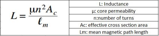
Fig.1 indicates the inductance definition formula. We selected the toroid common mode choke with inductance 295uH and E-I core common mode choke with inductance 270uH. (Test condition is 0.1 Volts with 1 Kilohertz) To be fair, both common mode choke used the same core material and wind the same turns. The detail shows in table2.
In [2], it gives us an equivalent circuit of the common mode choke validating up to 40Mhz. The test frequency range is 1Khz to 10Mhz in this experiment. The simplified equivalent model shows in Fig 2.
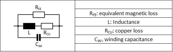
For the ideal common mode choke, the impedance would increase with the rising frequency. With the winding capacitance and other parasitic parameters, the relationship between impedance and frequency does not linearize. The test results show in Fig.3 and Fig.4
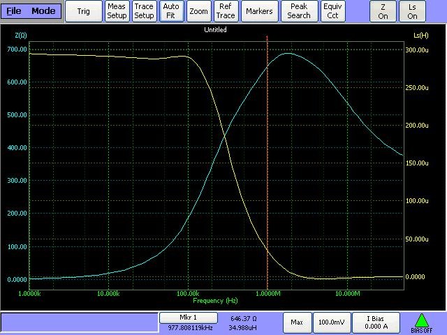
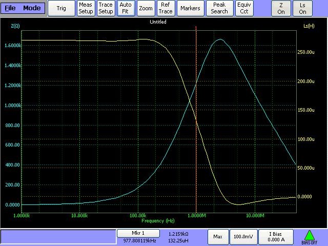
The marking line in Fig.3 and Fig.4 measuring the inductance and impedance at 977.808Khz. At this point, toroid common mode choke’s inductance is 34.988uH, E-I common mode choke’s inductance is 132.25uH. To compare the two shape common mode chokes inductance clearly, we pick up some key frequency points and redraw the inductance along with frequency plot. Shows in Fig.5.
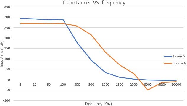
Obviously, toroid common mode choke has a higher inductance than E-I common mode choke before 100Khz, however, toroid common mode choke’s inductance drops dramatically as frequency above 100Khz.
4. Make use of the air gap
Calculate E-I common mode choke’s inductance with Fig.1’s formula. The inductance according to the formula should be 834.44uH.
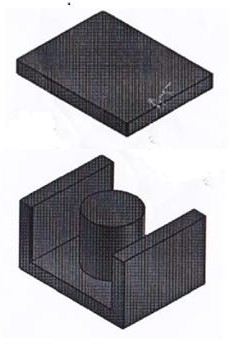
After a lot of research and consulting, the reason why the E-I core’s inductance much lower than calculation is there has the inartificial air gap in between E core and I core. Fig.6.
The effect of an air gap is to reduce the permeability and to make the coil’s characteristics less dependent upon the initial permeability of the core material. For other applicationsA gap helps prevent saturation under large AC or DC currents and allows better control of inductance, but in a common-mode choke, the flux from the two windings cancels each other. According to [6], the effective permeability formula shows in Fig.7.
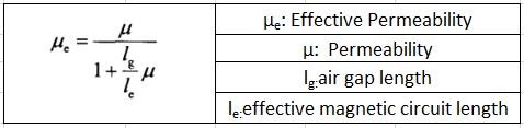
This formula is valid for closed magnetic cores of any geometry, provided that the initial permeability is high and the gap is relatively small. According to manufacturer data, the air gap between an E-core and an I-core typically ranges from 5 μm to 10 μm.
Calculate the effective permeability using E-I core’s parameters, see equation (1) for an example:
From Fig.7’s formula, the estimate air gap depth can be calculated, see equation (2) for an example:
The inartificial air gap between the test sample is about 6.8569um. Due to this air gap, the effect permeability becomes less sensitive to the frequency. On the other hand, toroid core makes up of ferrite without any air gap. Its permeability drops sharply as frequency above 100Khz. Fig.8 [7].
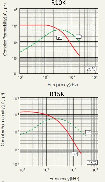
The most popular material for common mode choke is initial permeability 10000 Mn-Zn ferrite, such as R10K from DMEGC [7], T38 from EPCOS and W type from Magnetics. In most design solutions, engineer pursuits high permeability to build a high inductance common mode choke. The product’s frequency response is also important. In pursuit of high permeability will result in inductance and impedance dropping early. Below plot shows the initial permeability 10000 and the initial permeability 15000 material E-I core’s impedance with frequency response.
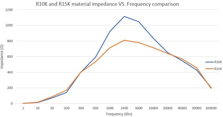
Clearly, the impedance of R10K material performs better than R15K material. The reason can be seen in Fig.8. R15K has poor frequency stability above 300Khz. Higher the permeability may not result high inductance.
Insertion loss of the common mode choke coil will be reduced when the ferrite core contact surface is polished [8]. The inartificial gap will reduce after polish, further, the air gap will reduce its height which will lead to less fringing effect and less loss.
5. Conclusion
Design a common mode choke does not need to care too much about core saturates and core loss. This makes designer chase a high permeability material to get a high inductance. After comparing the different core structure’s common mode choke, the truth is, different structure can also have an influence on the common mode choke even they have the same inductance. The micron level air gap in between E core and I core makes the effective permeability smaller than initial permeability and makes E-I structure common mode choke more robustness to frequency than toroid structure common mode choke.
References
[1]. M. Damnjanovic, L. Zivanov and G. Stojanovic, "Common mode chokes for EMI Suppression in Telecommunication Systems, " EUROCON 2007 - The International Conference on "Computer as a Tool", Warsaw, 2007, pp. 905-909.
[2]. A. Roc'h and F. Leferink, "In situ performances of common mode chokes, " 10th International Symposium on Electromagnetic Compatibility, York, 2011, pp. 494-499.
[3]. Differential and common mode noise- Murata .
[4]. Technical information from Magnetic INC. www.mag-inc.com
[5]. Nidhal Y. Nasser Assistant Lecturer ElectromechanicalEng. Dept. University of Technology. Journal of Engineering and Development, Vol. 16, No.1, March 2012 ISSN 1813- 7822
[6]. A. Ayachit and M. K. Kazimierczuk, "Steinmetz Equation for Gapped Magnetic Cores, " in IEEE Magnetics Letters, vol. 7, pp. 1-4, 2016, Art no. 1302704.
[7]. Technical information from DMEGC, R10K material and R15K material; www.chinadmegc.com
[8]. F. Amemiya, K. Takagi, N. Kuwabara, S. Hamada and Y. Iwamoto, "Developing a common-mode choke coil with high-permeability core used high-speed telecommunications port for UTP cable, " 2002 IEEE International Symposium on Electromagnetic Compatibility, Minneapolis, MN, USA, 2002, pp. 314-319 vol.1
Cite this article
Qian,Z. (2025). Comparison of Toroid and E-I Magnetic Core in Modern Common Mode Choke. Applied and Computational Engineering,206,37-44.
Data availability
The datasets used and/or analyzed during the current study will be available from the authors upon reasonable request.
Disclaimer/Publisher's Note
The statements, opinions and data contained in all publications are solely those of the individual author(s) and contributor(s) and not of EWA Publishing and/or the editor(s). EWA Publishing and/or the editor(s) disclaim responsibility for any injury to people or property resulting from any ideas, methods, instructions or products referred to in the content.
About volume
Volume title: Proceedings of CONF-FMCE 2025 Symposium: Semantic Communication for Media Compression and Transmission
© 2024 by the author(s). Licensee EWA Publishing, Oxford, UK. This article is an open access article distributed under the terms and
conditions of the Creative Commons Attribution (CC BY) license. Authors who
publish this series agree to the following terms:
1. Authors retain copyright and grant the series right of first publication with the work simultaneously licensed under a Creative Commons
Attribution License that allows others to share the work with an acknowledgment of the work's authorship and initial publication in this
series.
2. Authors are able to enter into separate, additional contractual arrangements for the non-exclusive distribution of the series's published
version of the work (e.g., post it to an institutional repository or publish it in a book), with an acknowledgment of its initial
publication in this series.
3. Authors are permitted and encouraged to post their work online (e.g., in institutional repositories or on their website) prior to and
during the submission process, as it can lead to productive exchanges, as well as earlier and greater citation of published work (See
Open access policy for details).
References
[1]. M. Damnjanovic, L. Zivanov and G. Stojanovic, "Common mode chokes for EMI Suppression in Telecommunication Systems, " EUROCON 2007 - The International Conference on "Computer as a Tool", Warsaw, 2007, pp. 905-909.
[2]. A. Roc'h and F. Leferink, "In situ performances of common mode chokes, " 10th International Symposium on Electromagnetic Compatibility, York, 2011, pp. 494-499.
[3]. Differential and common mode noise- Murata .
[4]. Technical information from Magnetic INC. www.mag-inc.com
[5]. Nidhal Y. Nasser Assistant Lecturer ElectromechanicalEng. Dept. University of Technology. Journal of Engineering and Development, Vol. 16, No.1, March 2012 ISSN 1813- 7822
[6]. A. Ayachit and M. K. Kazimierczuk, "Steinmetz Equation for Gapped Magnetic Cores, " in IEEE Magnetics Letters, vol. 7, pp. 1-4, 2016, Art no. 1302704.
[7]. Technical information from DMEGC, R10K material and R15K material; www.chinadmegc.com
[8]. F. Amemiya, K. Takagi, N. Kuwabara, S. Hamada and Y. Iwamoto, "Developing a common-mode choke coil with high-permeability core used high-speed telecommunications port for UTP cable, " 2002 IEEE International Symposium on Electromagnetic Compatibility, Minneapolis, MN, USA, 2002, pp. 314-319 vol.1