


1. Prelab Work
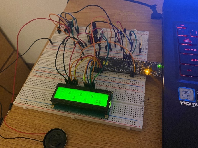
In the preparation work, we need to connect the circuits according to the figure below and ensure they are correct.
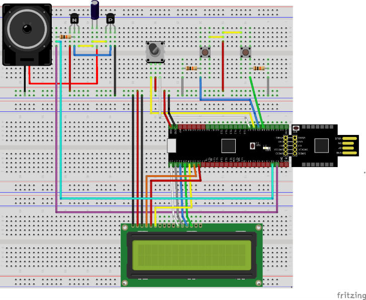
The following are all the materials needed:
Materials |
Quantity |
PSoC 5LP |
1 |
LCD Screen |
1 |
Resistor (10kΩ±5%) |
3 |
Capacitor (50V/100μF) |
1 |
Transistor (2N2222A-D) |
1 |
Transistor (2N3906) |
1 |
Speaker (8Ω-1W) |
1 |
Bread Board |
3 |
Wires |
Several |
Button |
2 |
2. Game
Description: This section focuses on how to use PWM, interrupt signals, and timers to create a parkour game. By pressing the button, the movement of the characters is controlled until they clear the level.
Requirement: Press the control button to move the character up and down, and then refresh the position when a new interrupt signal is given. Set a map with some obstacles in the system. When a character touches an obstacle, they lose one of their lives. When all three lives are lost, the game ends and the screen displays "Game Over". When the level is cleared successfully, the screen displays "Level Up!” and the map speed increases. Background music needs to be played in a loop during the entire game, and independent sounds are needed when crossing levels or hitting obstacles. The shapes of the character and obstacles should be defined by us.
Procedure: First, we need to identify the parts required for this experiment. Two buttons are needed to control the movement of the characters, so we need two "Input Pins". To keep the map moving to the left, we need a timer that runs throughout the game, constantly receiving interrupt signals and refreshing the screen. We also need two relatively independent PWMs to produce sounds: one for playing background music in a loop, and the other for playing collision, level completion, and prompt sounds at the end of the game.
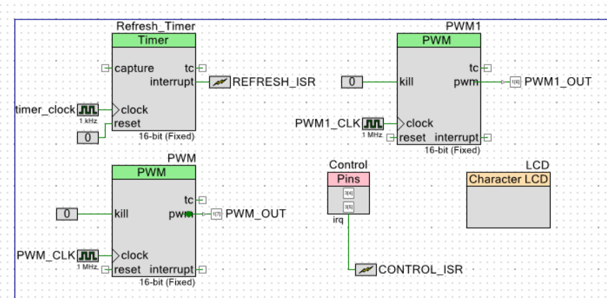
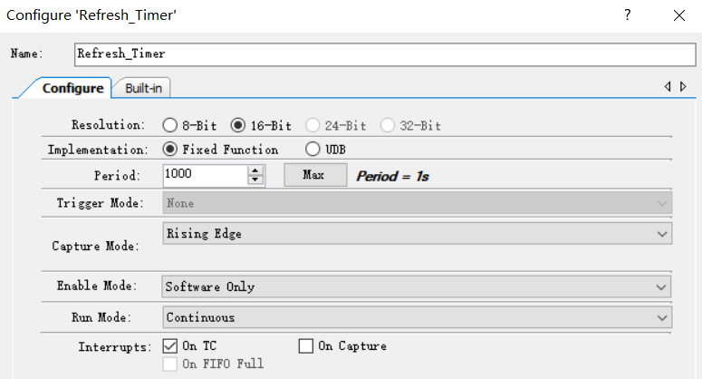
Let's start with TopDesign. First, we design a refresh timer that runs throughout the game. To make the map move to the left more slowly, we adjusted the clock pulse of the timer to a lower 1kHz. Connect a logic low level to the reset interface and an interrupt signal named "REFRESH_ISR" to the interrupt interface. Then, right-click the configuration, change the resolution to 16-bit, change the implementation to a fixed function, and check "On TC" in Interrupts.
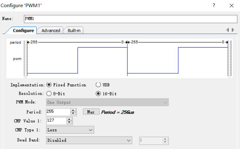
As shown above, we have already set the timer. The next step is to design two PWMs for playing music. These two PWMs have the same parameters except for the names and the music they play. So, we create two PWMs, one called PWM, which is used to play the prompt tone, and the other named PWM1, which is used to play the background music in a loop. We connect a logic 0 to both PWM kill ports and a "Digital Output Pin" to the interrupt port, which are renamed PWM_OUT and PWM1_OUT. The clock pulses of both are adjusted to 1MHz. In the configuration, change both configurations to: Fixed Function and 16-bit.
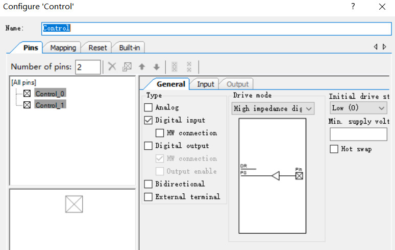
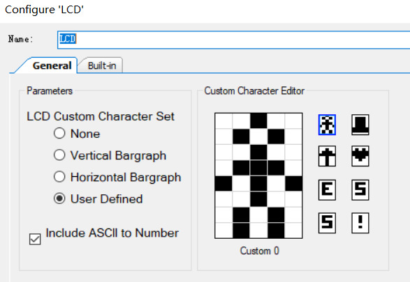
Then, we add two buttons to control the movement of the characters. We add a "digital input pin" and change the number of pins to 2 because we need one button to control upward movement and the other to control downward movement. Cancel the HW connection and change the driving mode to "High Impedance". Rename the button to Control, add an interrupt to it, rename it to CONTROL_ISR, and connect it to the IRQ port. Finally, we added an LCD and designed several icons to represent people and obstacles, completing all the previous designs.
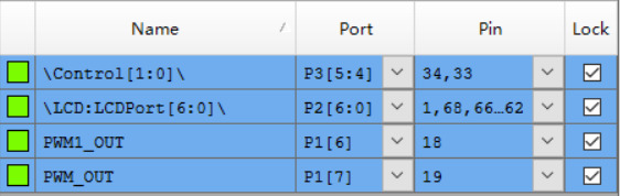
Finally, we connect the control buttons to P3[5:4], the LCD to P2[6:0], PWM1 for playing background music to P1[6], and PWM for playing prompt tones to P1[7].
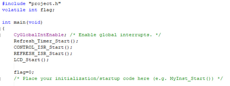
Next is the most important part: organizing ideas and writing code. First, we believe that, except for the background music which is played in a loop, everything else is controlled by the corresponding interrupt signal. Therefore, the code for playing background music should be placed in the loop program of the main function. The main program only needs to turn on the LCD, timer, refresh interrupt signal, and Control interrupt signal. In the main program, it is also necessary to define a variable flag that can be recognized in any interrupt signal and initialize it to 0.
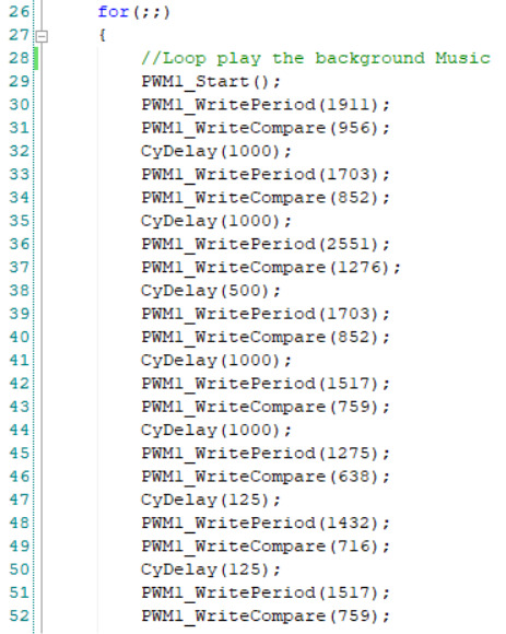
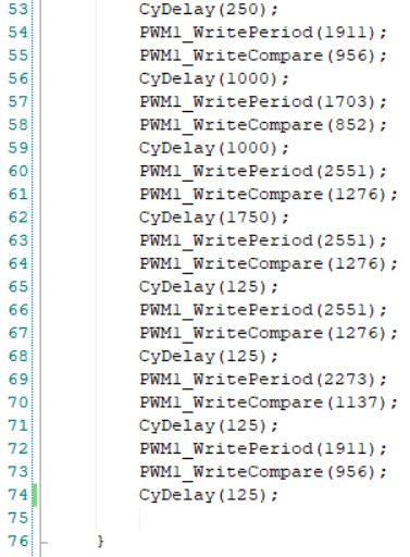
For the background music played in a loop, we first activate PWM1, and then write the frequency, compare, and duration of the tones to be played in sequence. The music I used here is "Never Gonna Give You Up".
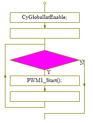
The following is the logic diagram of the main function:
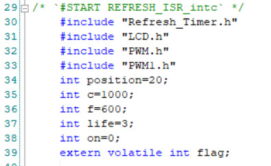
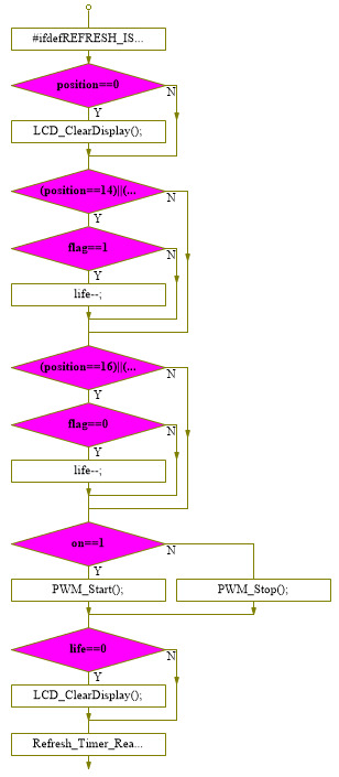
Then comes the code in REFRESH_ISR, which has many functions. First, we need header files including "Refresh_Timer.h", "LCD.h", "PWM.h", and "PWM1.h", indicating that this interrupt signal controls the timer, LCD, and two PWMs. We need to set the map. For example, here I set the length of the map to 20 frames, so I define an integer variable position=20. Let the frequency and compare of the initial map moving speed be F and C, and assign them initial values of 600 and 1000. Then, define a decision variable on for detecting whether a character hits an obstacle, initially set to 0. There is also a life value, life=3. Finally, an instant variable flag is defined, which controls and keeps the position of the characters.
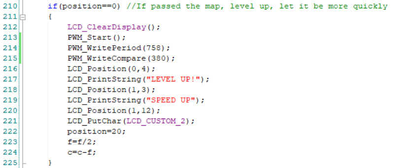
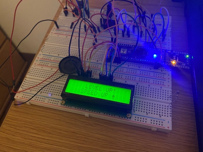
First, we should speed up every cycle of the map. We defined the variable c before, and use c as the cycle of each run. Then, design the map. We clearly describe the position of obstacles on the map in the form of coordinates, using our homemade symbols. For example, if there is an obstacle at (0,3), our coordinate should be (0, position-17). With the step-by-step reception of interrupt signals, these obstacles need to be translated to the left in turn. So here, we let the position decrease by one in turn. When the game is cleared, that is, when the position moves to 0 on the left, we need to start over and speed up. Therefore, add the judgment condition: when position==0, clear the screen, PWM plays the level completion prompt tone, and display "Level Up!”, reset the position to 20, and reduce the frequency and compare, to increase the speed.
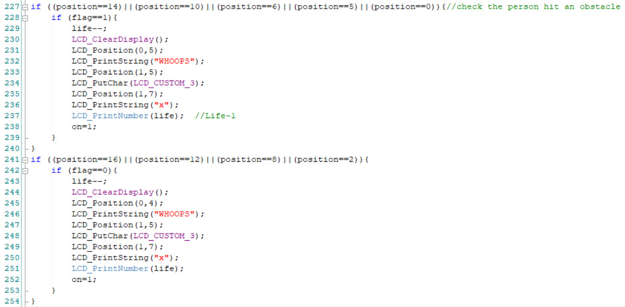
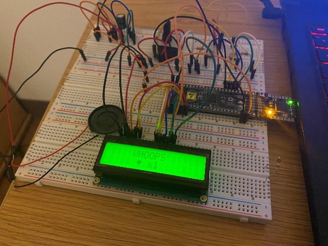
Next, it is necessary to detect whether a character has hit an obstacle. The current position of the character, represented by flag, will collide if it overlaps with the coordinates of any obstacle when it is detected that the character is in the position of (flag,0). If there is no overlap, there is no collision, and the game continues to run normally. In case of a collision, clear the screen and display "Whoops!”, reduce the life count by 1 and display the remaining life count, and set the variable on=1 to indicate a collision, and then continue the game.
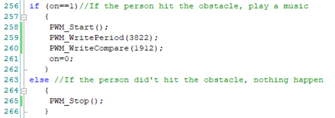
When the character collides with obstacles, PWM needs to produce a prompt tone, controlled by the variable on. When on==1, PWM turns on and plays a specific prompt tone, then resets on to its initial value. When there is no collision, PWM should be turned off.
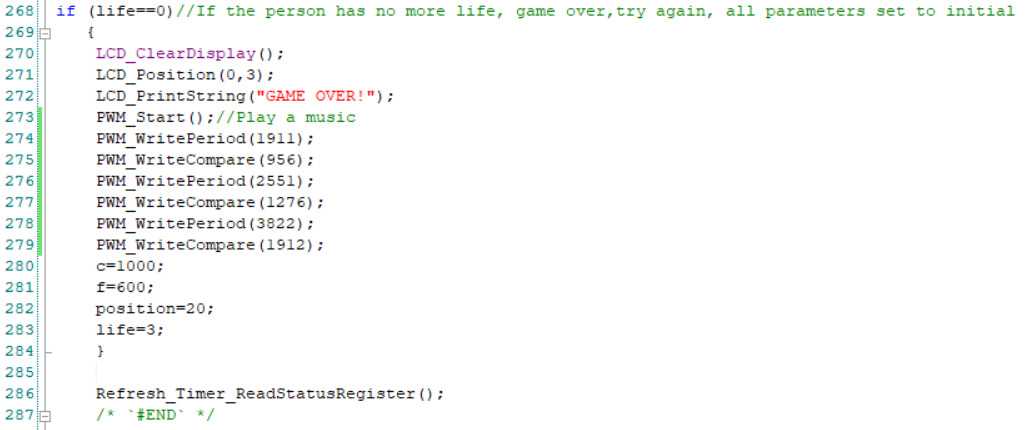
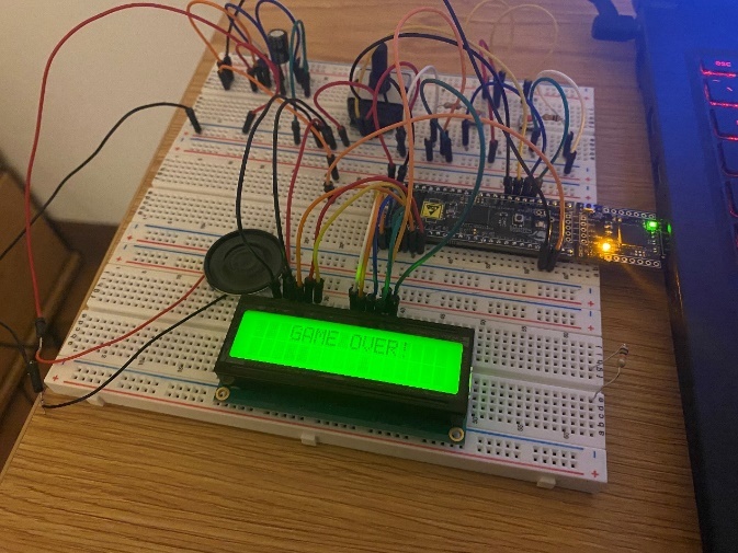
Then there is the code for detecting life. When life reaches 0, the game ends, the screen displays "Game Over", all parameters return to their initial values, PWM plays a prompt tone, and life is re-assigned to 3. At the end of the entire code, it is necessary to detect the current state of the timer, to maintain the original state and respond when each interrupt signal occurs.
The following is the logic diagram of REFRESH_ISR:
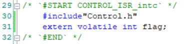
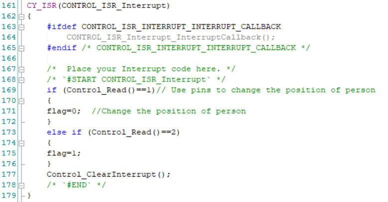
Finally, there is the code for the control button. This part is relatively simple, requiring the header file "Control.h" first, because it controls the interrupt signal of the control button. Then the previously defined variable flag is introduced, because the control button changes the value of flag, to achieve the function of changing the position of characters.
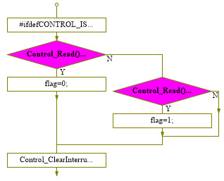
When we press the left button, the character moves up, so flag=0, because flag represents the position of the line where the character is located. Similarly, when the right button is pressed, the character moves down. At the end of the interrupt signal, we need to clear the current interrupt to maintain the previous state.
The following is the logic diagram of CONTROL_ISR:
The final experimental results are as follows:
3. Summary
In this experiment, the application of speakers, position detection, and control signals is comprehensively investigated. Adding random functions and various props to the game would make it more complete, although more complicated.
References
[1]. Semtech Corporation.Chirp Signal Processor: European, EP2975814A1[P].2016-01-20.
[2]. Ariel Ephrat and Shmuel Peleg. Vid2speech: speech reconstruction from silent video. In 2017 IEEE International Conference on Acoustics, Speech and Signal Processing, pages 5095-5099. IEEE, 2017.
[3]. Strap Technologics. https://strap.tech/. 4 December 2021.
Cite this article
Chen,Y. (2024). Creating a Parkour Game. Advances in Engineering Innovation,8,19-30.
Data availability
The datasets used and/or analyzed during the current study will be available from the authors upon reasonable request.
Disclaimer/Publisher's Note
The statements, opinions and data contained in all publications are solely those of the individual author(s) and contributor(s) and not of EWA Publishing and/or the editor(s). EWA Publishing and/or the editor(s) disclaim responsibility for any injury to people or property resulting from any ideas, methods, instructions or products referred to in the content.
About volume
Journal:Advances in Engineering Innovation
© 2024 by the author(s). Licensee EWA Publishing, Oxford, UK. This article is an open access article distributed under the terms and
conditions of the Creative Commons Attribution (CC BY) license. Authors who
publish this series agree to the following terms:
1. Authors retain copyright and grant the series right of first publication with the work simultaneously licensed under a Creative Commons
Attribution License that allows others to share the work with an acknowledgment of the work's authorship and initial publication in this
series.
2. Authors are able to enter into separate, additional contractual arrangements for the non-exclusive distribution of the series's published
version of the work (e.g., post it to an institutional repository or publish it in a book), with an acknowledgment of its initial
publication in this series.
3. Authors are permitted and encouraged to post their work online (e.g., in institutional repositories or on their website) prior to and
during the submission process, as it can lead to productive exchanges, as well as earlier and greater citation of published work (See
Open access policy for details).
References
[1]. Semtech Corporation.Chirp Signal Processor: European, EP2975814A1[P].2016-01-20.
[2]. Ariel Ephrat and Shmuel Peleg. Vid2speech: speech reconstruction from silent video. In 2017 IEEE International Conference on Acoustics, Speech and Signal Processing, pages 5095-5099. IEEE, 2017.
[3]. Strap Technologics. https://strap.tech/. 4 December 2021.