


1. Introduction
The primary function of a suspension system is to transmit the load between the wheels and the vehicle body, cushion or suppress road-induced vibrations and impacts, and ensure ideal wheel motion characteristics under varying road conditions and loads, thereby maintaining vehicle handling stability [1]. Suspensions are classified into independent and non-independent types based on the independence of wheel movement during operation. The five-link rear suspension is a type of independent suspension that employs five links working in coordination in space to constrain the rear wheel's movement trajectory. This design provides better control over wheel motion characteristics during driving, thereby enhancing handling stability [2].
As illustrated in Figure 1, the five-link rear suspension primarily consists of a rear subframe, front upper control arm, rear upper control arm, front lower control arm, rear lower control arm, toe link, steering knuckle, stabilizer bar, spring, shock absorber, and corresponding fasteners at connection points. In most cases, the front upper control arm, rear upper control arm, front lower control arm, and toe link function as load-bearing components, transmitting and absorbing loads from the steering knuckle to the subframe during vehicle movement. These four links are collectively referred to as two-force members. The structure of these links is relatively simple, consisting of a main body structure connected to the subframe and steering knuckle via bushings or ball joints. The main body is typically manufactured using processes such as sheet metal stamping, welding, aluminum alloy forging, or cast iron molding, as shown in Figure 2.
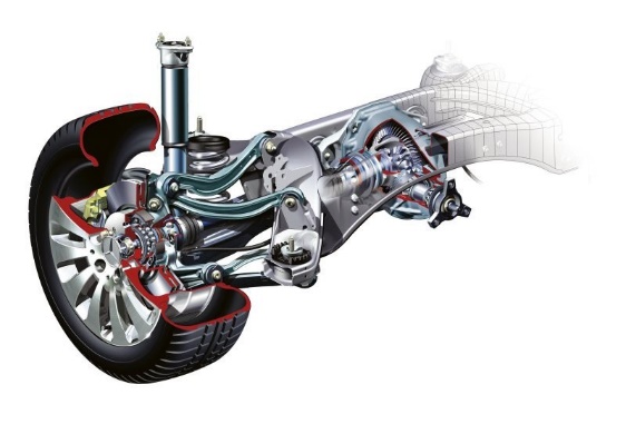
Figure 1. Schematic diagram of the five-link rear suspension
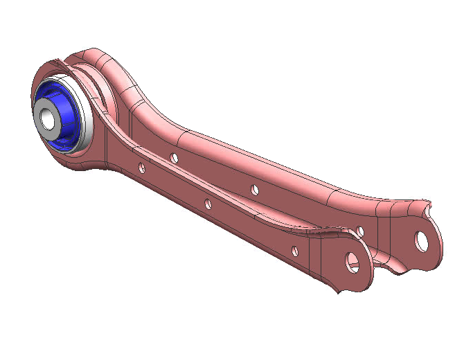
(a) Sheet metal stamping
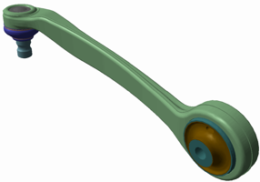
(b) Forging
Figure 2. Structural schematic of control arms
During the suspension system’s design and development process, the hard points and performance requirements vary according to different vehicle models and subsystem requirements, necessitating the redevelopment of various components. The structural design of control arm components is directly influenced by suspension hard points and performance requirements. Any change in these requirements necessitates a complete redesign and remodeling of the structure. Moreover, within the same vehicle model development, multiple design iterations are required to balance structural performance, weight, and other factors. Traditional modeling methods are inefficient and fail to meet the demand for high efficiency, which has become a significant challenge for companies.
This study focuses on the two-force control arms manufactured through sheet metal stamping and employs CATIA parametric modeling to achieve rapid structural design. This approach addresses the efficiency challenges faced by companies during development, enhances the design efficiency of five-link suspension components, shortens the design cycle, and establishes a theoretical and practical foundation for future intelligent chassis component design and development.
2. Structural design process of control arms
As illustrated in Figure 3, the conventional design process begins with structural modeling based on the received design requirements. Once the 3D model is completed, finite element analysis (FEA) is conducted to determine whether the design meets performance requirements. Additionally, the model's weight is assessed to ensure it satisfies lightweight design criteria. If the requirements are not met, the design is revised and iterated until both performance and lightweight standards are achieved. This study primarily focuses on the iterative process of 3D structural modeling and redesign.
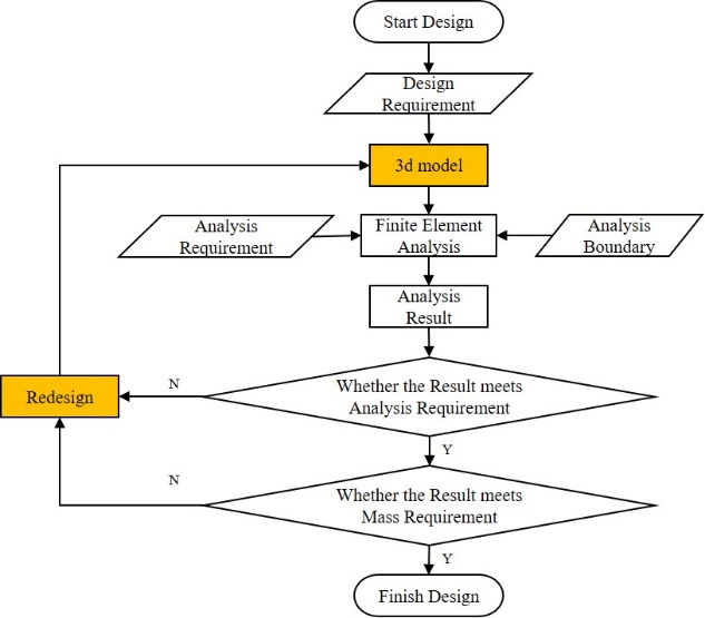
Figure 3. Schematic diagram of the conventional design process
Upon receiving the design input, a local coordinate system for the control arm is established based on the hardpoint coordinates at both ends of the control arm—where it connects to the subframe and steering knuckle—as well as the corresponding bushing axis directions. Typically, the hardpoints connected to the subframe are referred to as inner points, while those connected to the steering knuckle are referred to as outer points. The inner point serves as the origin of the local coordinate system, the bushing axis at the inner point defines the X-axis, and the line connecting the inner and outer points defines the Y-axis, as shown in Figure 4.
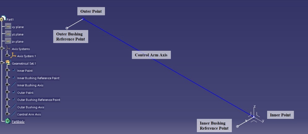
Figure 4. Schematic diagram of the local coordinate system for control arm modeling
In the X-Y plane and Y-Z plane of the local coordinate system, structural sketches of the front view and top view of the control arm are drawn. After extrusion and trimming, the basic sheet metal body of the control arm is obtained. Additional structural features such as bushing press-fit holes, bolt connection holes, and flange edges along the main profile are then incorporated. Finally, the thickness is added to the surfaces according to the control arm’s design specifications, forming the final structural design of the control arm, as illustrated in Figure 5.
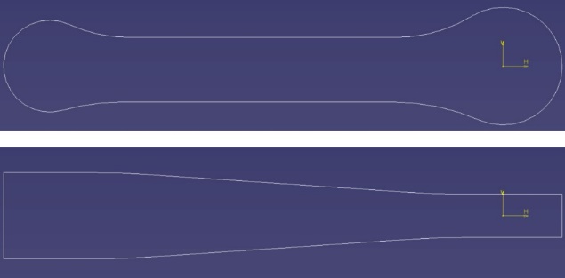
(a) Structural sketches of the front view and top view of the control arm
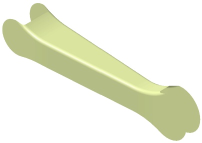
(b) Extrusion and trimming of sketches
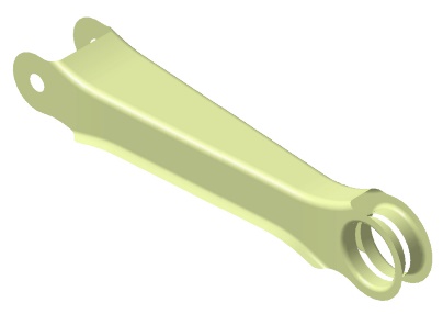
(c) Addition of structural features
(d) Surface thickening
Figure 5. Schematic diagram of the control arm structural design
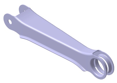
The above structure represents the most common two-force member control arm design. However, in practical applications, modifications are necessary to accommodate surrounding components, particularly in the case of the front upper control arm and rear upper control arm, which must be designed with downward-bent clearance structures to avoid interference with the underbody crossbeam during the vertical motion of the wheel, as shown in Figure 6. If the distance between the upper surface of the downward-bent structure and the control arm’s hardpoint axis is too small or even falls below the axis, stamping becomes infeasible. In such cases, the control arm must be designed as a two-piece stamped and welded structure, as shown in Figure 7. Additionally, certain control arms require designs where bushings are press-fitted on both sides, or where the opening direction is upward, as shown in Figures 8 and 9, respectively. Based on these considerations, a classification of control arm design types is summarized in Table 1.
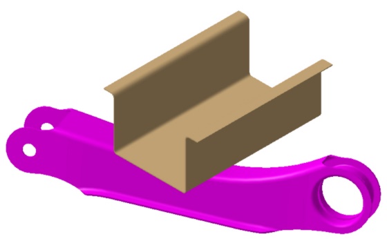
Figure 6. Schematic diagram of the front upper control arm avoiding the underbody crossbeam
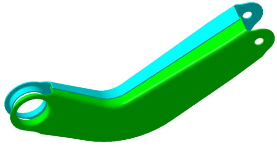
Figure 7. Schematic diagram of the two-piece welded front upper control arm
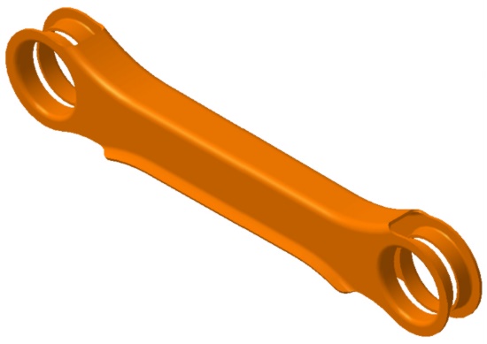
Figure 8. Schematic diagram of the control arm with bushings press-fitted on both sides
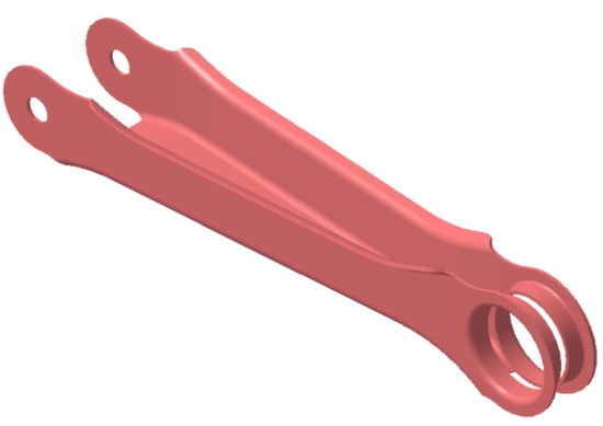
Figure 9. Schematic diagram of the control arm with an upward-opening structure
Table 1. Classification of Control Arm Designs
Avoidance of Underbody Crossbeam | Single-Side Bushing Press-Fit | Double-Side Bushing Press-Fit | ||
N (No) | Downward Opening | Upward Opening | N (No) | Downward Opening |
Y (Yes) | Single-Piece Stamping | Two-Piece Welding | Y (Yes) | Single-Piece Stamping |
3. Secondary development of visual basic and CATIA parametric modeling for design
The secondary development of software is an effective means of professionalizing the user experience, allowing the software to better and more precisely address user needs, thereby improving work efficiency and quality. CATIA provides secondary development interfaces and an internal command set, including V5 Automation for object-oriented programming and Component Application Architecture (CAA) for component-based application programming [3]. Visual Basic is an object-oriented visual programming language widely used in the Windows environment [4]. This study leverages Visual Basic and CATIA for secondary development to enable rapid design and model updates for control arm structures.
As discussed in the previous section, the key design processes of a control arm involve sketching in the X-Y and Y-Z planes within the local coordinate system, as well as defining various structural features. Several parameters influence sketch design and structural characteristics, including:
Outer diameter of the press-fit bushing
Bolt hole diameter
Upper surface height
Lower surface height
Inner point opening distance
Outer point opening distance
For control arms requiring a downward-bent structure, the axial distance between the lowest point of the upper surface and the hardpoint is also a critical design parameter, as it is influenced by the surrounding component envelope and the Y-position of the underbody crossbeam. Additionally, the flange chamfer at the bushing press-fit region and the chamfer between two perpendicular planes are both affected by the thickness of the control arm plate, as illustrated in Figure 10. Other structural design parameters can be constrained using formulas based on these key parameters. Therefore, the parameters listed above, along with the control arm’s inner and outer hardpoint coordinates and bushing axis reference points, are defined as key parameters, as summarized in Table 2.
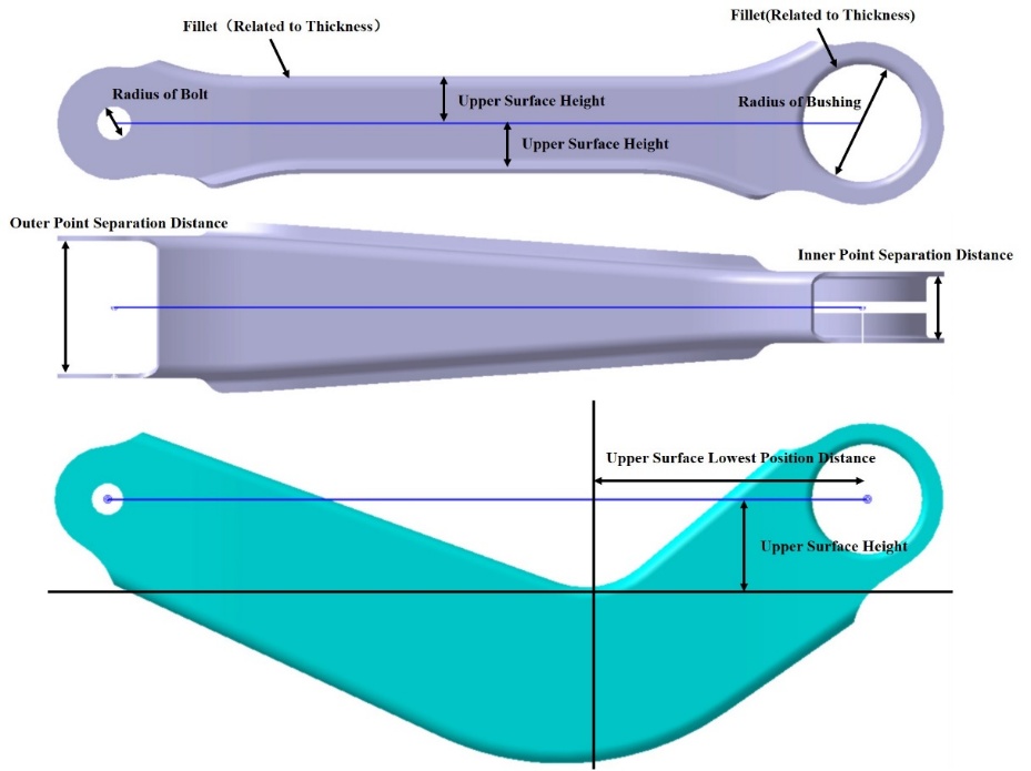
Figure 10. Schematic diagram of key control arm parameters
Table 2. Key Parameters for Control Arm Design
No. | Parameter Description |
1 | Inner point coordinate of the control arm |
2 | Inner point bushing axis reference point |
3 | Outer point coordinate of the control arm |
4 | Outer point bushing axis reference point |
5 | Outer diameter of press-fit bushing |
6 | Bolt hole diameter / Press-fit bushing hole diameter |
7 | Upper surface height |
8 | Lower surface height |
9 | Inner point opening distance |
10 | Outer point opening distance |
11 | Axial distance of the lowest point on the upper surface |
12 | Plate thickness of the control arm |
For non-critical structural features, feature parameter control can be achieved by establishing formula-based relationships using empirical design parameters. For example, as shown in Figure 11, based on stamping experience, the inner fillet radius of the bushing press-fit hole is typically 1.5mm, which means the outer fillet radius should be equal to the plate thickness + 1.5mm. Additionally, the outer diameter of the plane edge in the bushing press-fit region is controlled by the outer diameter of the bushing. Based on stamping experience, the flat section width of the stamped area should be at least three times the plate thickness. Thus, the edge outer diameter can be calculated using the formula: Outer diameter of edge = Press-fit bushing outer diameter + Outer fillet radius + 3 × Plate thickness = Press-fit bushing outer diameter + 4 × Plate thickness + 1.5mm By using formulas to define these relationships, all derived dimensions can be controlled by key parameters. This logic is implemented in CATIA’s formula module, as shown in Figure 12.
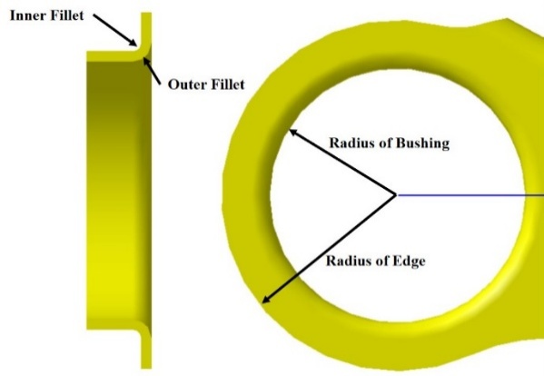
Figure 11. Schematic diagram of bushing press-fit hole dimensioning
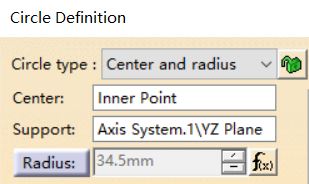
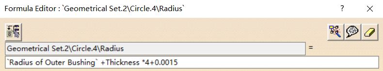
Figure 12. Formula function interface in CATIA
In the parametric design secondary development, the program design principle is illustrated in Figure 13. The user selects the control arm structure type to be modeled and inputs the corresponding design parameter values. The system then:
Connects Visual Basic to CATIA
Retrieves the CATIA Application object code to open the CATIA model [5]
Generates or updates the sketches and structural features corresponding to the selected model
Updates the overall structure of the model
Extracts the weight information of the part and displays it in the user interface output results [6][7][8]
The selection logic for control arm structural types is depicted in Figure 14.

Figure 13. Flowchart of secondary development program design
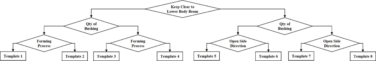
Figure 14. Decision logic for control arm structural type selection
Based on the above program design principles, the user interface was developed, and the corresponding code was implemented, as shown in Figure 15.
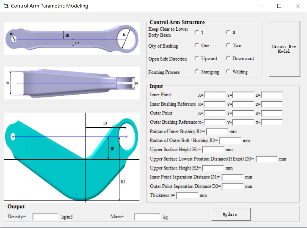
Figure 15. Schematic diagram of the program operation interface
4. Case study
To demonstrate the practical application of this secondary development, a case study was conducted on the front lower control arm of the rear suspension of a specific vehicle model. The key input parameters for this control arm design are shown in Table 3.
Table 3. Key Parameters for Control Arm Design
No. | Parameter Description | Design Input |
1 | Inner point coordinate of the control arm | (3428, -280, 15) |
2 | Inner point bushing axis reference point | (3454.132, 266.288, 21.722) |
3 | Outer point coordinate of the control arm | (3569, -560, 13) |
4 | Outer point bushing axis reference point | (3595.132, -546.888, 19.722) |
5 | Outer diameter of press-fit bushing (mm) | 25 |
6 | Bolt hole diameter (mm) | 7 |
7 | Upper surface height (mm) | 20 |
8 | Lower surface height (mm) | 14 |
9 | Inner point opening distance (mm) | 26 |
10 | Outer point opening distance (mm) | 56 |
11 | Plate thickness (mm) | 2 |
By using the parametric design secondary development program introduced in the previous section, users can enter each key parameter in the user interface and click "Create Model" to complete the structural design of the control arm. The software then outputs the weight information of the generated structure, as illustrated in Figure 16. After opening the generated model and conducting verification, both the geometric dimensions and weight information were confirmed to be accurate, as shown in Figure 17.
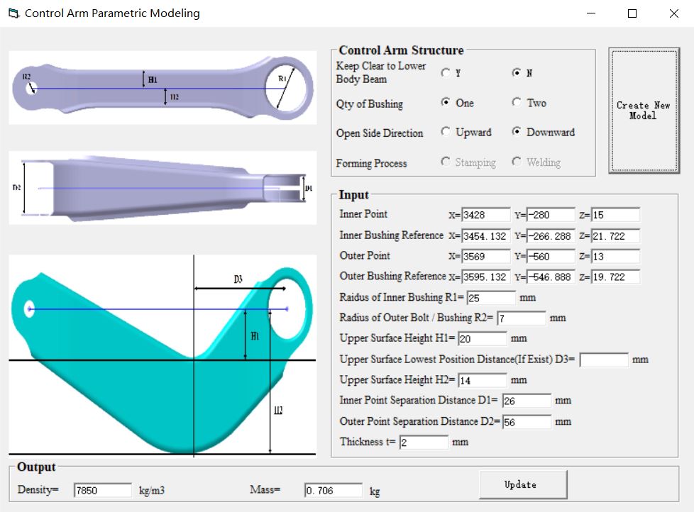
Figure 16. Case study operation interface
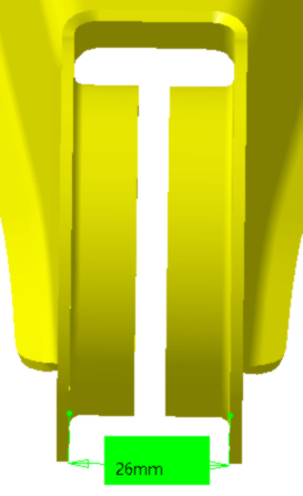
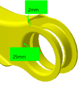
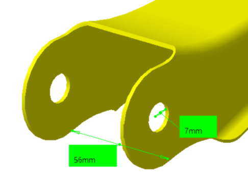
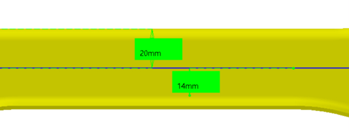
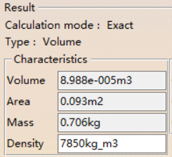
Figure 17. Verification results of the generated model
Following CAE analysis, the model required updates. By adjusting the key parameters in the user interface, the control arm model was quickly updated. The updated weight information was then evaluated to determine whether the lightweight requirements were met. Throughout the design and optimization process, the time required to create or update the model was extremely short. From inputting parameters to completing or updating the model, the total time was less than 5 minutes, with the majority of time spent entering parameters in the software interface. In comparison, a conventional initial model design takes over 30 minutes, while updating an existing model takes more than 10 minutes. This secondary development program significantly enhances design efficiency, achieving the research objective of improving modeling speed.
5. Conclusion
This study investigated the modeling and design process of sheet metal two-force member control arms, defining key design steps and parameters. A secondary development program was implemented using Visual Basic to enable parametric modeling in CATIA. The program was validated through a case study, demonstrating its effectiveness in improving design efficiency. The modeling process, which originally took 30 minutes, was reduced to under 5 minutes, resulting in a significant efficiency boost and addressing the design efficiency challenges faced by companies.
In future secondary development, integrating finite element simulation into the program, along with multi-objective optimization for performance validation, could establish a closed-loop control arm design workflow. This would further reduce the overall development cycle.
Additionally, by applying the same development approach and methodology to other chassis components, the concept of intelligent design could be extended to all structural components, ultimately building a comprehensive intelligent design and development system.
References
[1]. Li, S., & Li, Y. (Eds.). (2020). Modern design of automotive chassis. China Machine Press.
[2]. Jia, W., Ma, Z., Chen, H., et al. (2022). Kinematic analysis and DMU simulation of five-link rear suspension in automobiles. Automotive Practical Technology, 47(21), 102-107. https://doi.org/10.16638/j.cnki.1671-7988.2022.021.019
[3]. Hu, T., & Wu, L. (Eds.). (2006). Fundamentals of CATIA secondary development technology. Publishing House of Electronics Industry.
[4]. Lin, Z. (Ed.). (2021). VB programming language design. Publishing House of Electronics Industry.
[5]. Zhou, G., & Lu, W. (2010). Research and application of CATIA secondary development technology. Mechanical Design and Manufacturing, 2010(01), 81-83. https://doi.org/10.19356/j.cnki.1001-3997.2010.01.034
[6]. Lu, C., Chen, Q., & Ma, K. (2022). Research and application of CATIA secondary development for spline modeling in interactive functions. Journal of Hefei University of Technology (Natural Science Edition), 45(08), 1036-1039+1045.
[7]. Liu, Q., You, C., & Wang, H. (2022). CATIA secondary development-based modeling and attribute extraction for arch dam construction units. China Rural Water and Hydropower, 2022(12), 193-199+205.
[8]. Zhang, X., Hao, B., & Liu, T. (2015). Rapid modeling technology based on CATIA secondary development. Group Technology & Production Modernization, 32(03), 15-18+50.
Cite this article
Ge,Y. (2025). Application of Visual Basic-based CATIA parametric modeling in the structural design of control arms. Advances in Engineering Innovation,16(1),46-55.
Data availability
The datasets used and/or analyzed during the current study will be available from the authors upon reasonable request.
Disclaimer/Publisher's Note
The statements, opinions and data contained in all publications are solely those of the individual author(s) and contributor(s) and not of EWA Publishing and/or the editor(s). EWA Publishing and/or the editor(s) disclaim responsibility for any injury to people or property resulting from any ideas, methods, instructions or products referred to in the content.
About volume
Journal:Advances in Engineering Innovation
© 2024 by the author(s). Licensee EWA Publishing, Oxford, UK. This article is an open access article distributed under the terms and
conditions of the Creative Commons Attribution (CC BY) license. Authors who
publish this series agree to the following terms:
1. Authors retain copyright and grant the series right of first publication with the work simultaneously licensed under a Creative Commons
Attribution License that allows others to share the work with an acknowledgment of the work's authorship and initial publication in this
series.
2. Authors are able to enter into separate, additional contractual arrangements for the non-exclusive distribution of the series's published
version of the work (e.g., post it to an institutional repository or publish it in a book), with an acknowledgment of its initial
publication in this series.
3. Authors are permitted and encouraged to post their work online (e.g., in institutional repositories or on their website) prior to and
during the submission process, as it can lead to productive exchanges, as well as earlier and greater citation of published work (See
Open access policy for details).
References
[1]. Li, S., & Li, Y. (Eds.). (2020). Modern design of automotive chassis. China Machine Press.
[2]. Jia, W., Ma, Z., Chen, H., et al. (2022). Kinematic analysis and DMU simulation of five-link rear suspension in automobiles. Automotive Practical Technology, 47(21), 102-107. https://doi.org/10.16638/j.cnki.1671-7988.2022.021.019
[3]. Hu, T., & Wu, L. (Eds.). (2006). Fundamentals of CATIA secondary development technology. Publishing House of Electronics Industry.
[4]. Lin, Z. (Ed.). (2021). VB programming language design. Publishing House of Electronics Industry.
[5]. Zhou, G., & Lu, W. (2010). Research and application of CATIA secondary development technology. Mechanical Design and Manufacturing, 2010(01), 81-83. https://doi.org/10.19356/j.cnki.1001-3997.2010.01.034
[6]. Lu, C., Chen, Q., & Ma, K. (2022). Research and application of CATIA secondary development for spline modeling in interactive functions. Journal of Hefei University of Technology (Natural Science Edition), 45(08), 1036-1039+1045.
[7]. Liu, Q., You, C., & Wang, H. (2022). CATIA secondary development-based modeling and attribute extraction for arch dam construction units. China Rural Water and Hydropower, 2022(12), 193-199+205.
[8]. Zhang, X., Hao, B., & Liu, T. (2015). Rapid modeling technology based on CATIA secondary development. Group Technology & Production Modernization, 32(03), 15-18+50.