


1. Introduction
With the increasing complexity and intelligence of automotive electronic systems, the firmware update of ECU (Electronic Control Unit) has become the core link to ensure the functional safety and performance optimization of vehicles. If each update operation is completed by specific personnel in a specific location, the workload will be enormous. To solve this problem, remote update technology for automotive ECU named bootloader provides a more effective method. The bootloader on CAN is based on CAN bus and UDS services. CAN has a reliable data protection mechanism, while UDS has a security service flow. Therefore, the CAN Bootloader on this mechanism has obvious characteristics of fast, reliable, safe, reusable and easy management [1]. However, its functional stability and security need to be verified through systematic automated testing [2]. Traditional manual testing methods are inefficient and have limited coverage, and to develop an automated test system can solve these problems. The purpose of this paper is to discuss the design and implementation of the bootloader automated test system which automatically generates, conducts and evaluates test cases [3].
2. Test requirements analysis
2.1. Bootloader download test analysis
In order to make the process of bootloader download have strict security control, usually the bootloader has a fixed download process. Figure 1 illustrates one common download processes. The pre-programming phase conditions the new firmware download to ensure that the upgrade takes place in a safe and secure environment. Formal programming is the main body of the upgrade process, requiring security verification, memory erasure, data transfer, and checking for integrity and dependencies. The data transfer step is repeated until all logical blocks are transferred. The purpose of the post-programming step is to restore the ECU to a normal working state and run with the new firmware.
The Bootloader download test can be divided into functional test, reliability test, security test and robustness test. 1) Functional test is mainly used to verify whether the bootloader can correctly update the application and calibration under normal circumstances, and other functions and configurations will not be affected before and after the update. 2) Reliability test is to verify that the bootloader can make correct processing under abnormal conditions, and the ECU can still upgrade the software without becoming a brick. Exceptions can be power and communication interruptions, missing download steps, data transmission interruptions, etc. 3) Security test mainly tests the correctness of ECU unlocking, signature and dependency algorithms. In addition, when there is an illegal data source download or the download data has been tampered with needs to be identified. 4) The robustness test mainly verifies that the download can still be performed correctly under some extreme environments, such as voltage fluctuations and high bus load rate. The download success rate of the download durability test is also verified.
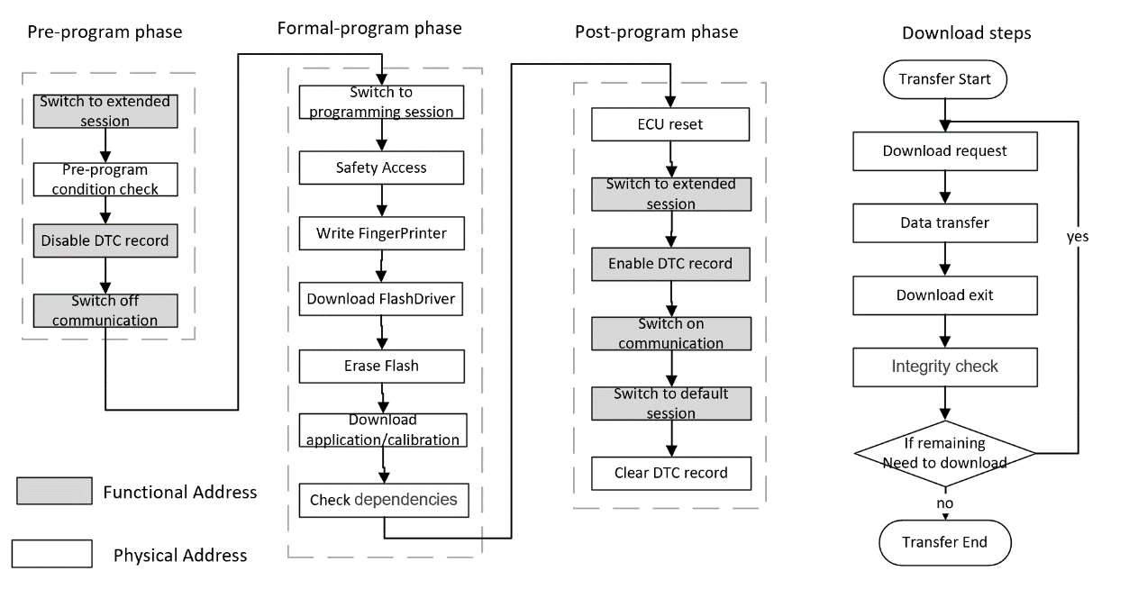
Figure 1. Download process
2.2. Protocol conformance test analysis
The CAN bus integrates error detection and correction mechanisms, enhancing data integrity and exhibiting high resilience against electrical interference [4]. Therefore, the CAN bus is still one of the first choices for bootloaders. Both DoCAN and UDS on CAN are diagnostic protocols based on CAN bus, but DoCAN focuses more on transport layer and network layer services, while UDS on CAN provides more extensive application layer diagnostic services. UDS is an application-layer protocol developed by ISO to implement diagnostic communication functions [5], which implements functions such as diagnosis, configuration, and software update of ECUs through a series of specific services. Table 1 lists the most commonly used diagnostic requests in bootloaders. 0x10 Diagnostic Service is to switch session services to meet the operational requirements of different stages of reprogramming. 0x11 Service is the ECU reset service. After the firmware update is complete, you need to reset the ECU. 0x27 Security Access Service is used to verify access to diagnostic devices preventing unauthorized access and operations to ensure system security. 0x28 Communication Control Service can control the communication function of the ECU. For example, enable or disable a specific communication port or protocol to ensure the stability and accuracy of communication during operations such as software updating. 0x85 is the DTC Control service. To disable DTC recording can prevent unexpected faults from being recorded during firmware upgrade. 0x22 and 0x2E can read and write specific data from the ECU such as the fingerprint, calibration data, etc. The 0x31 Routine Control Service can be used to perform certain routines, such as erasing ECU memory before software is written. 0x34 The Request Download Service is used to initiate a data download request, informing the ECU that a data download is coming. 0x36 The Transfer Data Service is responsible for the actual data transfer process, transferring software update data, etc., to the ECU. 0x37 Download Exit Service is used to notify the ECU to exit the download mode after data download is completed.
Table 1. The UDS service is commonly used in bootloaders
Service | Description | Service | Description |
0x10 | Session Switch | 0x22 | Read Data By DID |
0x11 | ECU reset | 0x2e | Write Data By DID |
0x27 | Safety Access | 0x31 | Routine Control |
0x28 | Communication Control | 0x34 | Request Download |
0x85 | DTC Set Control | 0x36 | Data Transfer |
0x37 | Download Exit |
The network layer protocol in the bootloader is responsible for solving problems such as data length mismatch between the data link layer and the application layer, and provides a method of splitting into multiple frames if the data to be transmitted is not suitable for a single CAN frame [6] to ensure that the data is reliably transmitted on the bus. When the amount of data to be transmitted is relatively small (CANFD ≤ 64 bytes, CAN ≤ 8 bytes), the data can be transmitted within one frame, that is, single-frame transmission. Multi-frame transmission is used for cases where the data volume is large (CANFD > 64 bytes, CAN > 8 bytes), and the data needs to be transmitted in multiple frames. Multi-frame transmission includes First Frame (FF), Flow Control (FC), and Consecutive Frame (CF). 1) FF: The sender transmits the first frame first, which contains key information such as the total length of the data to be transmitted subsequently, allowing the receiver to understand the data scale in advance and make preparations for reception. For example, when transmitting ECU firmware update data, the first frame will inform the receiver of the size of the entire firmware data. 2) FC: After receiving the first frame, the receiver will reply with a flow control frame according to its own receiving capacity and current state to the sender. The flow control frame is used to control the transmission rhythm of data, such as giving instructions to the sender whether to continue sending (allow sending), pause sending (waiting), or stop sending, to ensure that the receiver does not cause overflow or loss due to too fast data reception. 3) CF: The sender transmits consecutive frames according to the instructions of the flow control frame at the prescribed rhythm. Each consecutive frame contains part of the data content, and multiple consecutive frames together constitute the complete large data. The receiver receives these consecutive frames in sequence and, after receiving all of them, reassembles the data based on the information provided in the first frame to restore the original large data, achieving reliable transmission of large data in the network. Figure 2 shows the transmission processes of single frames and multi-frames.
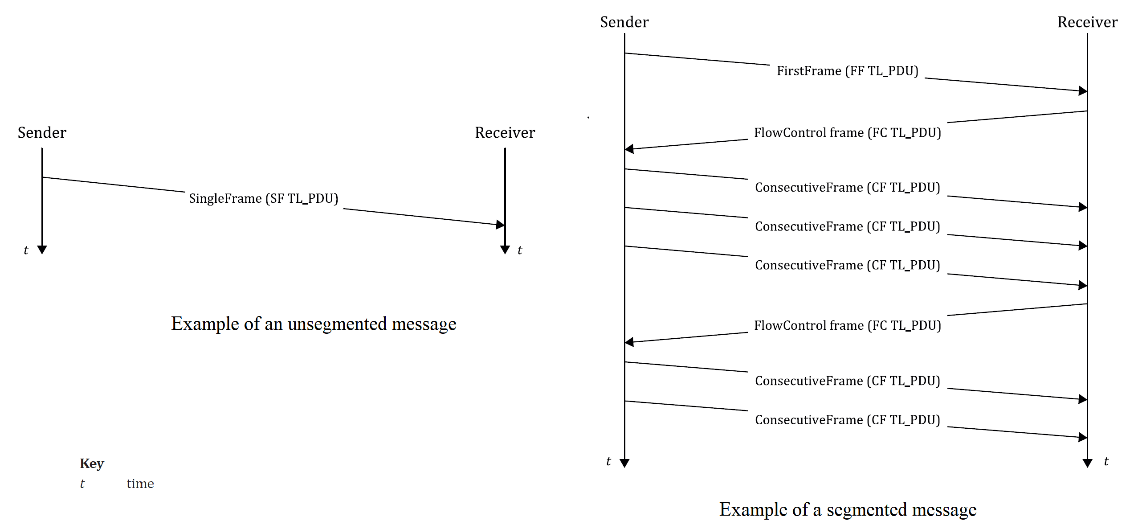
Figure 2. Transmission process of single frames and multi-frames
Whether the UDS and network layer protocols meet the protocol requirements affects the stability of CAN communication during software update. Therefore, protocol consistency test is crucial. Test requirements can be divided into UDS protocol test and network layer protocol test. The reference standard of the UDS test is ISO14229-1, and the test is divided into these aspects: diagnostic request and response format, NRC response priority, and diagnostic service prerequisites. The reference standard of the network layer test is ISO15765-2, and the test is divided into these aspects: multi-frame and single-frame mechanism, network layer parameters, and addressing mode.
3. Test system design
3.1. Test system architecture design
According to the test requirements, we can design a test system architecture. In terms of features, the test system needs to be easy for testers to operate, to cover all test cases, to facilitate the expansion of test cases, to adapt to different projects quickly. The test process is highly automated, and the test report is easy to view. In terms of functionality, the testing system needs to be able to send, receive, and parse CAN messages, generate communication and power supply faults, and parse all kinds of downloaded files. In addition, a testing management system is needed to record project information and interact with the project management system, easy to upload and track the failed items.
Based on these characteristics, considering the practicability and cost, we designed a set of bootloader automated test system architecture as is shown in Figure 3. The hardware system consists of a test computer, a CAN interface card, a test board, and a programmable power supply. The software system consists of a testing management system, a configuration panel, a testing script, and a testing report generation module. The testing management system is at the top of the software architecture. It is used to fill in project information, select test cases, and generate test projects. On the other hand, it can interact with various testing software modules. In addition, it can also interact with project management software to upload failed items discovered during testing, making it convenient for project team members to track issues. At the same time, project team members can automatically arrange test plans by importing them from the project management system into the testing management system. The configuration panel is a testing configuration tool which is convenient for setting test parameters, loading related files. It can also be used to set the parameters of the current test project, such as CAN diagnostic physical and functional addressing IDs, network layer parameters, reset and diagnostic interval times, etc.
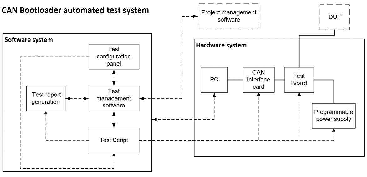
Figure 3. Architecture diagram of the bootloader automated test system
3.2. Test cases library development
The test cases should have a fixed format like Excel or CSV. This way, on the one hand, it is convenient for us to build a test case library, such as importing the cases into MySQL or some test management tools like TestRail, Xray, and Polarion. On the other hand, the fixed fields facilitate the future intelligent development of test scripts using AI.
When designing test cases, first divide the test cases into two major modules based on the test requirements: the download test and the CAN protocol conformance test. Then, break down each test module into several test groups. The download test module can be divided into four groups: functional test, reliability test, security test, and robustness test. The CAN protocol conformance test module can be divided into three groups: UDS conformance test, CAN network layer conformance test, and CAN communication conformance test. According to the test direction of each test group, it can be further detailed into specific test items and sub-cases. In this way, we can build test items. For example, the test items for the security test are shown in Table 2.
Table 2. Security download of the test case list
Test Group | Test Case | Description |
Security Download Test | TG1_TC1 | Download without passing security access |
TG1_TC2 | Download with the false digital signature | |
TG1_TC3 | Download with the data tampered | |
TG1_TC4 | Download with incomplete data | |
TG1_TC5 | Download with the wrong fingerprint | |
…… | …… |
Once the test items are listed, we can perform a detailed test case design for each test item. For example, as shown in Table 3, this test case is designed for the scenario where data is tampered with during the firmware download process by the bootloader, to verify the ECU's data integrity verification mechanism and its ability to handle exceptions. The test case simulates data tampering during the transmission phase (such as modifying specific bytes in consecutive frames), and requires the ECU to detect illegal data and perform the following security actions: 1) Return a negative response (NRC: 0x24 or 0x31) indicating data verification failure; 2) Refuse to write the tampered data, ensuring that only legitimate firmware is retained in memory; 3) The ECU remains reprogrammable to prevent it from becoming bricked. The test case design covers the security upgrade requirements in the Bootloader design. When designing the test case, further expandable scenarios should be considered include testing different tampering locations (such as data segment, CRC segment), to comprehensively evaluate the ECU's security protection capabilities.
Table 3. Security download of the test case list
Test case ID | TG3_TC3 |
Test case name | Data was tampered with during the download process |
Test condition | 1. ECU in programming session (0x10 0x02 Executed) |
2. Secure Access unlocked (0x27 Service Complete) | |
3. Download process to request download (0x34 service) | |
Test procedure | 1. Send 0x3601 [valid data block] (for example, 0x3601 11 22 33 44 55 66 77). |
2. Modify the data in subsequent frames (for example, change the data in frame 2 0x21 88 99 AA BB CC DD to 0x21 FF 99 AA BB CC DD). | |
3. Send the modified data frame. | |
4. Send 0x37 request to exit transmission. | |
Expected result | 1. The ECU detects data tampering and returns a negative response (NRC: 0x7F36 24, verification failed). |
2. The ECU refuses to write the modified data. | |
3. No tampered data is written to the memory. | |
4. The ECU can reprogramm successfully | |
Test result | (Fill in after execution) |
priority | high |
Requirements Associated | Boot RS 3.3 |
3.3. Test script development
Test script is the core of the whole test system and the key of test automation. The development of automated testing scripts can be done using CAPL, Python, or C++. It adapts the project by importing the test configuration and does not require manual modification. The test script reads the data from the download file and parses it into the CAN diagnostic message that needs to be sent. Diagnostic requests and responses during the download process can be sent and received through the built-in library functions in the development environment. In addition, peripherals used during the testing process, such as CAN communication interface cards, test board and programmable power supply can be interacted with by calling DLL files in the test scripts so as to realize the automatic test [7]. Similarly, the algorithm library files used during the download process can also be called in test scripts to achieve ECU unlocking and verification of download integrity. Test logs can be automatically recorded and named using the log recording module. Typically, log files are saved as .asc or .blf files. The test report can be presented in HTML format, and the reasons for pass or fail, fault injection points, and the project information can be added to the report to improve readability. Test reports and test logs can be quickly linked for easy viewing.
4. Test system validation
4.1. Test system integration and verification
We choose Python to develop the test management system and configuration panel, use CAPL to write test scripts, and C++ to develop DLL files. Finally, we integrate these components to form a CAN bootloader automated test system. We only need to fill in the project information in the test management system, and then fill in the configuration parameters in the configuration panel according to the project requirements to load the corresponding download files and DLL files as is shown in Figure 4. Then, a test project suitable for the project we need to test can be generated. In the test management system, we can check the cases to be executed, and the test will automatically run without any operation during this period. After the test is completed, the test report and test log will be automatically generated and uploaded to the project management system for reading by developers and testers.
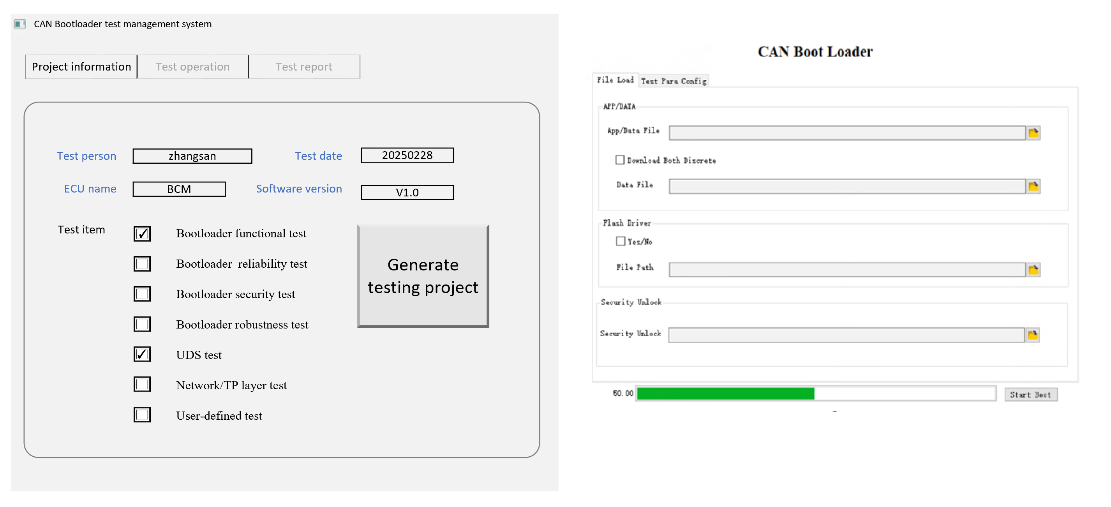
Figure 4. CAN bootloader test management system and configuration panel
In addition, we also integrated CANoe with Jenkins to achieve the automation arrangement of test tasks. Jenkins is an open source automation tool for Continuous Integration (CI) and Continuous Delivery (CD) in software development. It can call the COM interface or command line of CANoe through batch processing or Python scripts to start the test project. Then, CANoe will execute the predefined test cases and generate test reports in HTML/XML format. Jenkins collects the reports through post-processing tasks and publishes them to the platform, and triggers emails for notification based on the test results. The entire process supports parameterized builds and can be tested in parallel on multiple nodes. If linked with version control systems such as Git, it can automatically trigger tests after code submission to ensure continuous integration and efficient verification of automotive electronic systems.
4.2. Test quality and efficiency analysis
The use of the automated CAN bootloader testing system has brought about significant improvements in both quality and efficiency. Our test system encompasses a total of 285 sub-uses cases. As is shown in Figure 5, we finished the reliability tests, and both the summary of tests and the records of test processes are presented in the test report. Calculated based on a single bootloader write operation taking 30 seconds, a complete round of testing can be accomplished in just 4 hours. If manual testing is employed, these tests would take several weeks to complete. Even with a semi-automatic testing system, it still requires one to two weeks, with a testing efficiency increase of over 10 times. Meanwhile, the existence of our test case library enables continuous iteration and accumulation of more test cases, enhancing test coverage. Manual writing and management of test cases are prone to omitting cases, resulting in insufficient testing. In addition, this highly integrated testing system has a more stable testing environment, less likely to be interrupted, and more stable communication. The testing quality is also much higher than that of traditional testing systems.
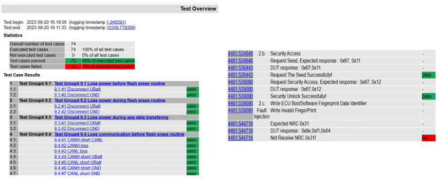
Figure 5. Test report
5. Summary
The entire test system achieves fully automated testing of Bootloader by integrating various software modules and hardware interfaces. With the continuous evolution of automotive electronic systems, Bootloader testing systems will also face more challenges and opportunities. Future research directions can focus on intelligent testing, automated script optimization, and more efficient security verification mechanisms to address the increasingly complex automotive network environment and constantly upgrading network security threats. Through continuous innovation and optimization, the Bootloader testing system based on CAN bus will provide solid technical support for the development of the automotive electronics industry.
References
[1]. Zhang, Y., & Bao, K. (2011). Design and implementation of Vehicle Controller BootLoader. Computer Engineering, 37(12), 233-235.
[2]. Miucic, R., & Mahmud, S. M. (2025). Wireless multicasting for remote software upload in vehicles with realistic vehicle movement. In Proc. SAE World Congress (pp. 11-14).
[3]. Luo, F., Tong, Y., & Hu, F. (2024). Research on CAN FD Transceiver Interoperability Automated Test System. In 2024 IEEE Vehicle Power and Propulsion Conference (VPPC) (pp. 1–7).
[4]. Ayachit, V., Gandhi, N., & Kakade, S. (2024). Unified Diagnostics Off-board Tool Development Testing. SAE Technical Paper, 2024-01-5041. https://doi.org/10.4271/2024-01-5041
[5]. International Organization for Standardization. (2020). ISO 14229-1: Road vehicles – Unified Diagnostic Service (UDS) - Specifications and requirements.
[6]. International Organization for Standardization. (2024). ISO 15765-2: Road vehicles - Diagnostic communication over Controller Area Network (DoCAN) - Transport protocol and network layer services.
[7]. Chang, J. (2014). Development of CAN bus test system [Master’s thesis, Tongji University].
Cite this article
Qian,J.;Luo,F.;Hu,F. (2025). Development of CAN bootloader automated test system. Advances in Engineering Innovation,16(2),25-31.
Data availability
The datasets used and/or analyzed during the current study will be available from the authors upon reasonable request.
Disclaimer/Publisher's Note
The statements, opinions and data contained in all publications are solely those of the individual author(s) and contributor(s) and not of EWA Publishing and/or the editor(s). EWA Publishing and/or the editor(s) disclaim responsibility for any injury to people or property resulting from any ideas, methods, instructions or products referred to in the content.
About volume
Journal:Advances in Engineering Innovation
© 2024 by the author(s). Licensee EWA Publishing, Oxford, UK. This article is an open access article distributed under the terms and
conditions of the Creative Commons Attribution (CC BY) license. Authors who
publish this series agree to the following terms:
1. Authors retain copyright and grant the series right of first publication with the work simultaneously licensed under a Creative Commons
Attribution License that allows others to share the work with an acknowledgment of the work's authorship and initial publication in this
series.
2. Authors are able to enter into separate, additional contractual arrangements for the non-exclusive distribution of the series's published
version of the work (e.g., post it to an institutional repository or publish it in a book), with an acknowledgment of its initial
publication in this series.
3. Authors are permitted and encouraged to post their work online (e.g., in institutional repositories or on their website) prior to and
during the submission process, as it can lead to productive exchanges, as well as earlier and greater citation of published work (See
Open access policy for details).
References
[1]. Zhang, Y., & Bao, K. (2011). Design and implementation of Vehicle Controller BootLoader. Computer Engineering, 37(12), 233-235.
[2]. Miucic, R., & Mahmud, S. M. (2025). Wireless multicasting for remote software upload in vehicles with realistic vehicle movement. In Proc. SAE World Congress (pp. 11-14).
[3]. Luo, F., Tong, Y., & Hu, F. (2024). Research on CAN FD Transceiver Interoperability Automated Test System. In 2024 IEEE Vehicle Power and Propulsion Conference (VPPC) (pp. 1–7).
[4]. Ayachit, V., Gandhi, N., & Kakade, S. (2024). Unified Diagnostics Off-board Tool Development Testing. SAE Technical Paper, 2024-01-5041. https://doi.org/10.4271/2024-01-5041
[5]. International Organization for Standardization. (2020). ISO 14229-1: Road vehicles – Unified Diagnostic Service (UDS) - Specifications and requirements.
[6]. International Organization for Standardization. (2024). ISO 15765-2: Road vehicles - Diagnostic communication over Controller Area Network (DoCAN) - Transport protocol and network layer services.
[7]. Chang, J. (2014). Development of CAN bus test system [Master’s thesis, Tongji University].