


1. Introduction
With the rapid development of the automotive industry, the complexity of vehicle system software has increased significantly, making the complete elimination of software vulnerabilities before vehicle delivery impossible. In order to reduce recall costs caused by software defects, online software update capabilities are required to be supported by numerous Electronic Control Units (ECUs) in modern vehicles. In this context, program update methods based on Controller Area Network (CAN) communication have been adopted, but several limitations are presented by these approaches [1]. For instance, the absence of transport layer protocol support prevents the correct sequencing of message transmissions from being guaranteed. Moreover, the validity and reliability of downloaded data cannot be ensured due to the lack of validation of the downloaded data and proper security verification for accessors. Bootloaders based on protocols such as Unified Diagnostic Services (UDS) and CAN Calibration Protocol (CCP) have been employed to enhance the stability and reliability of software upgrades [2, 3]. However, due to the absence of standardized definitions for software structure and interfaces, the reusability of the software across different requirements has been found to be insufficient. Consequently, an online update software architecture compliant with Hersteller Initiative Software (HIS) standards and applicable to multiple hardware platforms has been proposed [4]. Nevertheless, the functional design of application layer modules related to diagnostics and programming control has not been further detailed, resulting in a high degree of coupling.
Current research on Bootloader software primarily focuses on implementation methods for different hardware platforms and the design of layered software architectures. However, notable deficiencies remain in the modular design of programming management functions, making it difficult to fully accommodate various diagnostic standards, reprogramming specifications, and customization requirements. To address these challenges, this paper presents a detailed design of a programming management framework with configurable architecture that supports programming sequence management and diagnostic message processing, based on an analysis of Bootloader functional scenarios. The reusability of the proposed solution under different downloading requirements is validated.
The structure of this paper is as follows: Section 2 introduces the fundamental concepts of Bootloader based on the UDS protocol. Building upon this foundation, Section 3 details the design methodology of the Bootloader software architecture, the interaction interfaces among modules, and the implementation of the Reprogramming Sequence Manager. Section 4 verifies the feasibility of the proposed solution across various downloading requirements. Finally, Section 5 concludes the paper with a summary and relevant conclusions.
2. UDS protocol-based ECU bootloader
The primary functionality for ECU software upgrades is implemented by the Bootloader, which is responsible for correctly receiving application or calibration data transmitted from a client, writing it to predefined storage spaces, and validating the integrity of the downloaded data. As illustrated in Figure 1, the Bootloader consists of three components: the Boot-Manager, the Reprogramming Software, and the Flash Driver. The Flash Driver is stored in the Random Access Memory (RAM) area, while the Boot-Manager and the Reprogramming Software reside in a protected flash region. The application software is allocated to the programmable region.
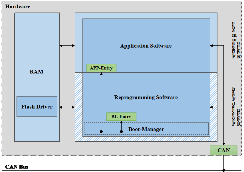
Figure 1. Block diagram of bootloader software structure
The Boot-Manager is designed to manage startup states and control the timing of transitions between diagnostic sessions. The Reprogramming Software is executed exclusively during programming requests, managing all diagnostic services and application programming control functionalities within the reprogramming workflow. The Flash Driver provides interfaces for erasing and writing operations on flash memory. To mitigate severe security risks caused by abnormal Flash operations, the Flash Driver must be loaded into the RAM area during programming tasks and cleared upon completion.
The ECU reprogramming process comprises three phases: pre-programming, main programming, and post-programming. During the pre-programming phase, the primary objective is to verify whether current conditions meet ECU online upgrade requirements. This phase involves network environment configuration, deactivation of non-diagnostic communication, and suspension of Diagnostic Trouble Code (DTC) logging functionality to ensure the ECU enters an appropriate programming state. The main programming phase focuses on authorizing external programming devices, downloading flash driver and application data, and validating all downloaded content. The post-programming phase restores the network environment by reactivating non-diagnostic communication and DTC logging across all ECUs, followed by switching the diagnostic session back to the default mode. After the application update process is completed, the ECU should transition from running the Bootloader to executing the updated application. The Boot-Manager is responsible for performing the program jump based on the application's entry address, ensuring the ECU functions correctly with the upgraded software.
3. Implementation of bootloader programming management feature
3.1. Layered software architecture of bootloader
In practical applications, Bootloader is deployed on different hardware platforms. The layered design of the software architecture and the standardized interface definition allow hardware-related components to be platformized, facilitating the reusability of Bootloader software modules and the extensibility of functionalities.
The Automotive Open System Architecture (AUTOSAR) achieves the standardization and platformization of basic software related to ECU hardware by defining standardized software functional components and interaction interfaces. This ensures the independence of application layer software from the underlying hardware-related software modules. The software architecture defined by AUTOSAR adopts a layered structure, centered around the Runtime Environment (RTE). The application layer and the basic software layer interact through the RTE standard interface to enable data exchange among various modules [5, 6]. As shown in Figure 2, referencing the layered software architecture of AUTOSAR and considering the functional requirements of Bootloader along with module reusability, the software is divided into five layers from bottom to top: the MCU Abstraction Layer, the ECU Abstraction Layer, the Service Layer, the RTE Runtime Environment, and the Application Software Layer.
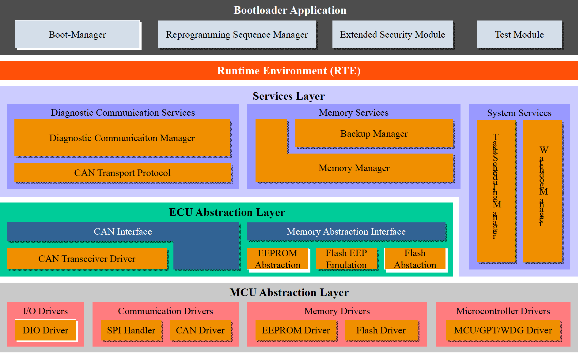
Figure 2. Layered software architecture of flash bootloader
The MCU Abstraction Layer implements only the chip hardware driver code required for Bootloader. It includes general digital I/O drivers supporting CAN communication, CAN drivers, and SPI Handler drivers, as well as EEPROM drivers and FLASH drivers supporting erase and storage functions. Additionally, it includes MCU drivers, General-Purpose Timer (GPT) drivers , and Watchdog (WDG) drivers for system services. The ECU Abstraction Layer abstracts the ECU hardware structure and provides a unified access interface for upper layers. This layer consists of the CAN transceiver driver, memory abstraction, and memory abstraction interface. The Service Layer provides services required during the programming process. It includes the Diagnostic Communication Manager (DCM) and Transport Protocol Layer, which implement diagnostic service functions, as well as the Memory Manager and Backup Manager, which enable logical block erasure, data writing, and data backup. Additionally, it contains the system service modules for task scheduling and watchdog management. Within the Bootloader Application Layer, the Boot-Manager and Reprogramming Sequence Manager handle server startup and reprogramming state and process management, while the Extended Security Module provides cryptographic computation interfaces as needed.
3.2. Standardized interfaces and interaction methods
In AUTOSAR, software interfaces are categorized into three types: standard interfaces for communication between basic software modules, AUTOSAR interfaces for communication between application layer execution entities and between execution entities and basic software service layer modules, and standardized AUTOSAR interfaces for specific service ports within certain service function modules in the basic service layer.
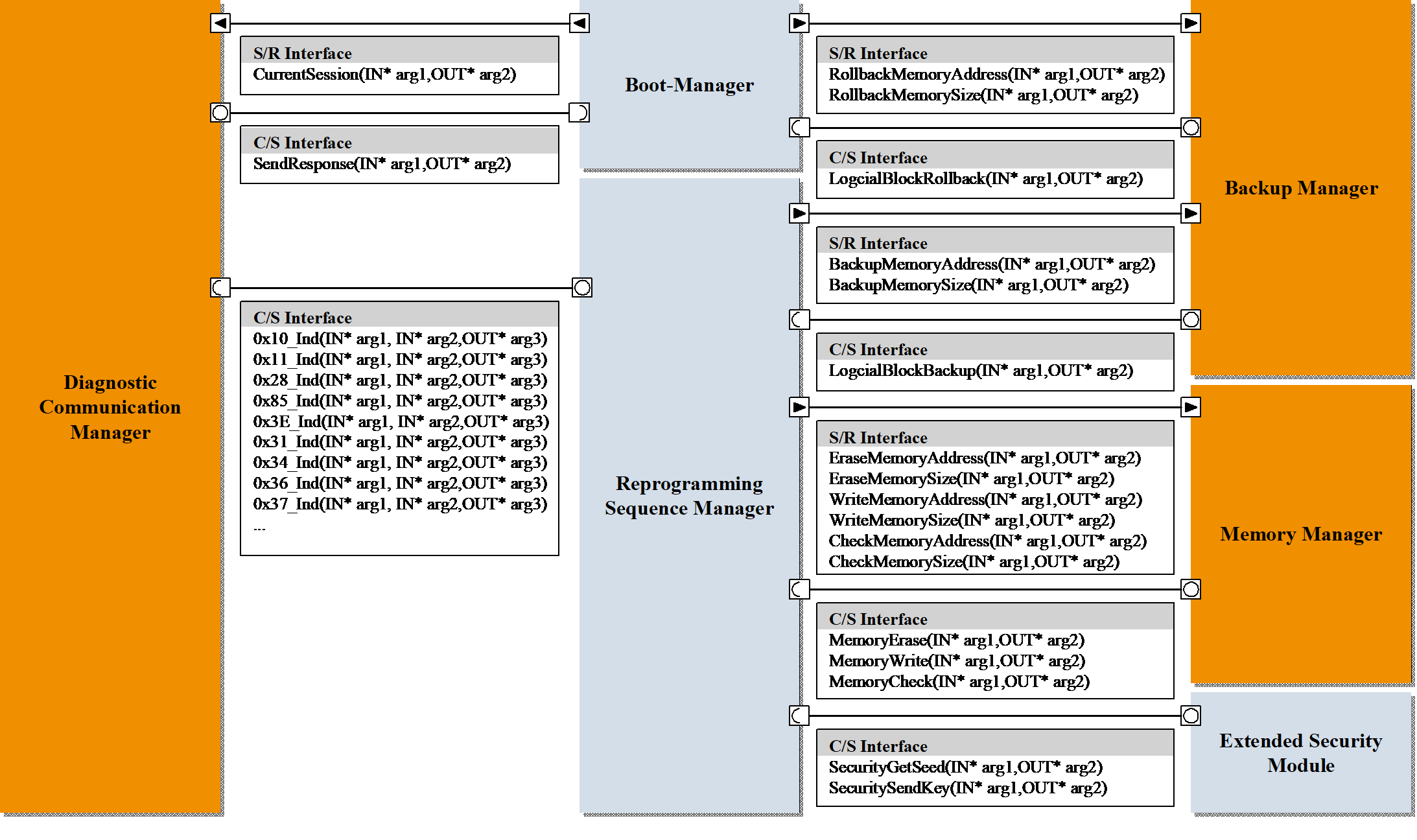
Figure 3. Interfaces of programming management-related modules
The programming process management functions are implemented through the collaboration of three types of modules: the programming step requester, the manager, and the executor. To accommodate the differences between diagnostic communication and programming processes, AUTOSAR interfaces are used for data and service provisioning between modules. As illustrated in Figure 3, programming management-related modules utilize Sender/Receiver (S/R) type interfaces for information transmission and reception, and Client/Server (C/S) type interfaces for event triggering and result feedback. The Diagnostic Communication Manager, acting as the requester of programming steps, triggers the execution of programming steps through an asynchronous C/S interface after receiving a valid diagnostic service request. It then verifies execution results and retrieves return data. The Reprogramming Sequence Manager, serving as the manager of programming steps, sets input parameters for programming operations using the S/R interface upon receiving a programming step request. It triggers the execution of programming operations via an asynchronous C/S interface and monitors execution results.
3.3. Configurable reprogramming sequence manager
Differences in the Bootloader programming process significantly impact software implementation. A well-structured programming process management method helps prevent unnecessary modifications to the software architecture. The Reprogramming Sequence Manager, which is responsible for managing the programming process and handling parameters of reprogramming steps, is designed to mitigate the effects of requirement discrepancies on the software architecture.
During the programming process, a single diagnostic service may require multiple operation steps, and each operation step can trigger a specific event within an executor managed Runnable Entity, which subsequently initiates predefined actions. As depicted in Figure 4, the Reprogramming Sequence Manager identifies the operation steps and event sequences to be executed and controls their timing and data flow during execution.
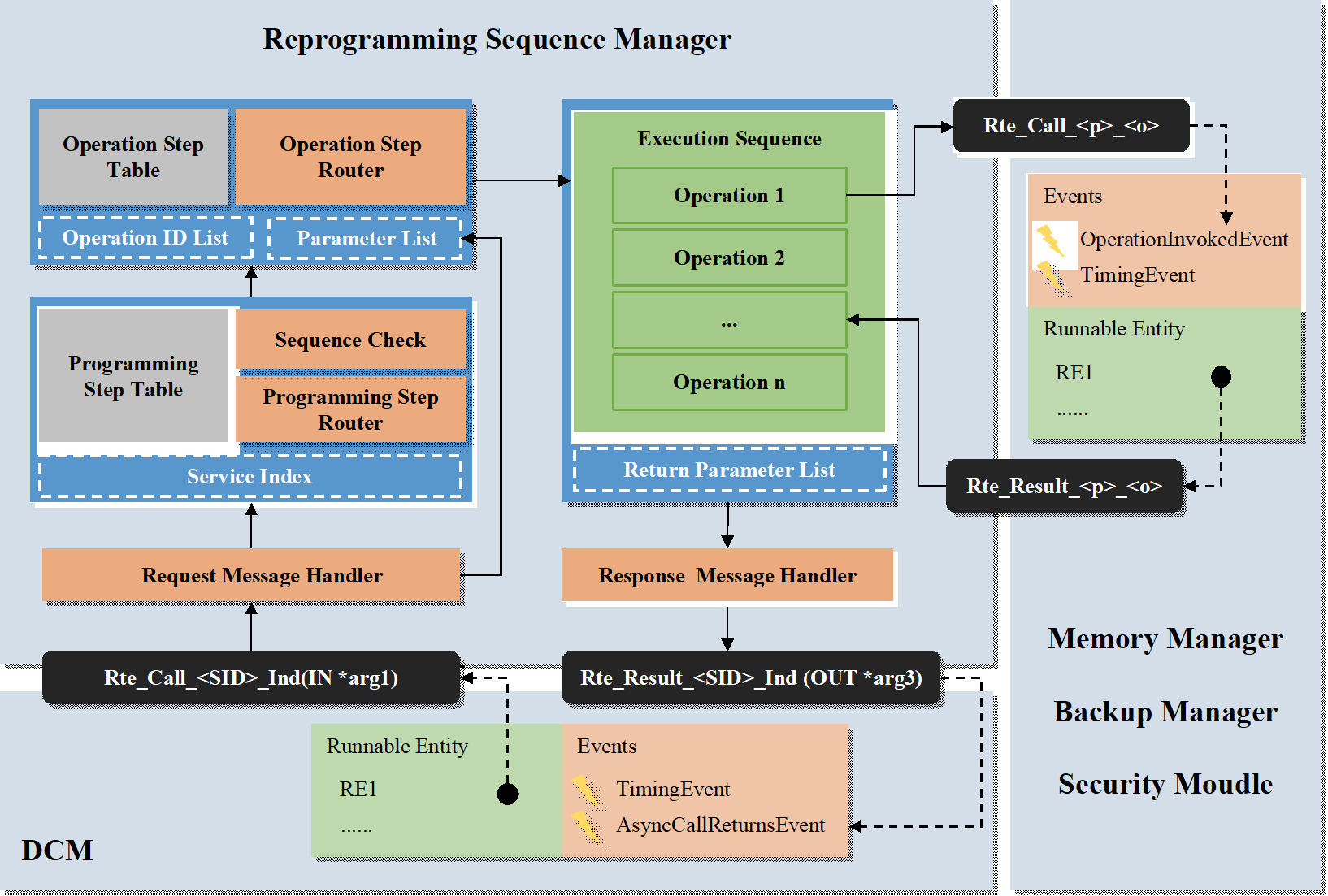
Figure 4. Data flow diagram of programming process management
When the requester of programming steps, DCM, receives a valid request, the Rte_Call function of the asynchronous C/S interface is invoked to transmit the requested service type, sub-function, and parameter information to the Reprogramming Sequence Manager. After receiving the diagnostic request, the Reprogramming Sequence Manager requests the message processor to obtain the service identifier and execution event parameter list from the diagnostic request. The service identifier is submitted to the Programming Step Router, while the parameter list is submitted to the Operation Step Router. The Programming Step Router retrieves the programming step configurations based on the service identifier, and the Sequence Check Module verifies whether the prerequisite steps have been executed. Subsequently, the Operation Step Router obtains the list of operation steps associated with each programming step and the relevant event execution parameters. These are serialized and loaded into the execution sequence of operation steps. The operation steps within the execution sequence are carried out sequentially, with each step executed only after the previous one is completed. The operation steps trigger the execution of associated events through the asynchronous C/S interface, retrieve execution results, and return data. If an event execution fails, the subsequent operation steps will not proceed. Upon failure in timing verification or after the completion of the execution sequence, execution results and return data are submitted to the response message processor. The appropriate service Rte_Result function is then invoked to notify DCM of the execution result of the service request.
4. Testing of the bootloader download feature
In this study, the parameter configuration, code implementation, and functional testing of Requirement A and Requirement B have been completed. Table 1 presents the differences between the two requirements in terms of logical block erasure, data download, and verification processes.
Table 1. Differences between requirement A and requirement B
Programming Service | Requirement A | Requirement B | |
RoutineControl (EraseMemory) | Request | 31 01 FF00 LogicalBlockIdentifier | 31 01 FF00 MemoryAddress MemorySize |
Response | 71 01 FF00 EraseResult | 71 01 FF00 EraseResult | |
RequestDownload | Request | 34 00 44 MemoryAddress MemorySize | 34 00 44 MemoryAddress MemorySize |
Response | 74 01 80 | 74 02 0400 | |
TransferData | Request | 36 BlockSequenceCounter TransferData(126 bytes) | 36 BlockSequenceCounter TransferData(1022 bytes) |
Response | 76 BlockSequenceCounter | 76 BlockSequenceCounter | |
RequestTransferExit | Request | 37 CRC | 37 |
Response | 77 CRC CheckResult | 77 | |
RoutineControl (CheckMemory) | Request | NA | 31 01 0202 CRC |
Response | NA | 71 01 0202 CheckResult | |
These differences include:
1. In the EraseMemory routine, the range of memory to be erased is represented by logical block numbers in Requirement A, whereas in Requirement B, it is indicated using memory addresses and memory size.
2. In the TransferData services, due to the relatively limited RAM resources of the hardware, the maximum length of returned data blocks in Requirement A is 128 bytes, while in Requirement B, it is 1024 bytes.
3. When verifying the validity of the downloaded data, Cyclic Redundancy Check (CRC) information is included in the RequestDownloadExit service of Requirement A, whereas in Requirement B, the routine control service is used to check whether the CRC is correct.
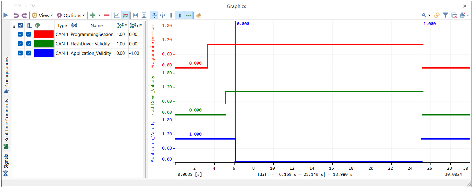
Figure 5. Timing diagram of internal variables during the download of requirements A
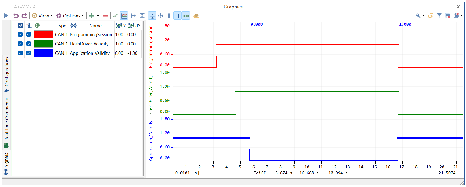
Figure 6. Timing diagram of internal variables during the download of requirements B
Figure 5 and 6 show the timing diagrams of programming status variables output by the internal test module of the Bootloader via CAN messages. The rising edge of the red graphic indicates the start of programming, while the falling edge indicates its completion. The Flash Driver is considered loaded when the green graphic is high. The application is being downloaded when the blue graphic is low. For Requirement A, the Data Block size is set to 128. The Flash Driver loading, Flash erasure, and other programming preparation processes take a total of 1.973 seconds. When a data size of 256k bytes is downloaded, a total of 2080.5 (2081) TransferData services are required, resulting in a total duration of 18.980 seconds. For Requirement B, the Data Block size is set to 1024. The Flash Driver loading, Flash erasure, and other programming preparation processes take a total of 1.545 seconds. When a data size of 256k bytes is downloaded, a total of 256.5 (257) TransferData services are required, resulting in a total duration of 10.994 seconds.The data download features for both requirements have been perfectly implemented. It demonstrates that the software method is applicable to different reprogramming requirements, possesses reusability, and can stably achieve the reprogramming function.
5. Conclusion
A Bootloader programming management method applicable to different programming standards was designed and implemented in this study. Through the adoption of a layered architecture and internal RTE interfaces, the programming initiation module and service execution module were kept independent from the management module. This structural configuration enabled flexible adaptation of required modifications while maintaining system integrity, thus enhancing software reusability. Verification processes for two Bootloader configurations with different requirements were successfully completed, demonstrating the effectiveness of this reusable methodology.
References
[1]. Tan, T., Tang, H., & Zhou, Y. (2013). Design and Implementation of Bootloader for Vehicle Control Unit Based on Can Bus. Proceedings of the FISITA 2012 World Automotive Congress, 194, 447-457. https://doi.org/10.1007/978-3-642-33829-8_42
[2]. Luo, F., & Xie, Y. Y. (2016). LIN Flash Bootloader Based on UDS. Journal of Automation and Control Engineering, 4(1), 47-52.
[3]. Wu, Y., Wen, K., & Liang, X. (2017). Design and Implementation of Bootloader Based on CCP Protocol. 2017 10th International Conference on Intelligent Computation Technology and Automation (ICICTA), 140-143. https://doi.org/10.1109/ICICTA.2017.38
[4]. Cheng, A., Xiong, L., Xie, M., & Li, Y. (2016). Design and Implementation of Online Upgrade Software for Vehicle ECU Based on HIS Standard. International Journal of Science, 3(1), 98-105.
[5]. Bunzel, S. (2011). AUTOSAR-the Standardized Software Architecture. Informatik-Spektrum, 34(1), 79-83. https://doi.org/10.1007/s00287-010-0506-7
[6]. Long, R., Li, H., Peng, W., Zhang, Y., & Zhao, M. (2009). An Approach to Optimize Intra-ECU Communication Based on Mapping of AUTOSAR Runnable Entities. In 2009 International Conference on Embedded Software and Systems, 138-143. https://doi.org/10.1109/ICESS.2009.63
Cite this article
Wu,Q.;Luo,F. (2025). A UDS-based ECU bootloader programming management framework with configurable architecture. Advances in Engineering Innovation,16(2),86-91.
Data availability
The datasets used and/or analyzed during the current study will be available from the authors upon reasonable request.
Disclaimer/Publisher's Note
The statements, opinions and data contained in all publications are solely those of the individual author(s) and contributor(s) and not of EWA Publishing and/or the editor(s). EWA Publishing and/or the editor(s) disclaim responsibility for any injury to people or property resulting from any ideas, methods, instructions or products referred to in the content.
About volume
Journal:Advances in Engineering Innovation
© 2024 by the author(s). Licensee EWA Publishing, Oxford, UK. This article is an open access article distributed under the terms and
conditions of the Creative Commons Attribution (CC BY) license. Authors who
publish this series agree to the following terms:
1. Authors retain copyright and grant the series right of first publication with the work simultaneously licensed under a Creative Commons
Attribution License that allows others to share the work with an acknowledgment of the work's authorship and initial publication in this
series.
2. Authors are able to enter into separate, additional contractual arrangements for the non-exclusive distribution of the series's published
version of the work (e.g., post it to an institutional repository or publish it in a book), with an acknowledgment of its initial
publication in this series.
3. Authors are permitted and encouraged to post their work online (e.g., in institutional repositories or on their website) prior to and
during the submission process, as it can lead to productive exchanges, as well as earlier and greater citation of published work (See
Open access policy for details).
References
[1]. Tan, T., Tang, H., & Zhou, Y. (2013). Design and Implementation of Bootloader for Vehicle Control Unit Based on Can Bus. Proceedings of the FISITA 2012 World Automotive Congress, 194, 447-457. https://doi.org/10.1007/978-3-642-33829-8_42
[2]. Luo, F., & Xie, Y. Y. (2016). LIN Flash Bootloader Based on UDS. Journal of Automation and Control Engineering, 4(1), 47-52.
[3]. Wu, Y., Wen, K., & Liang, X. (2017). Design and Implementation of Bootloader Based on CCP Protocol. 2017 10th International Conference on Intelligent Computation Technology and Automation (ICICTA), 140-143. https://doi.org/10.1109/ICICTA.2017.38
[4]. Cheng, A., Xiong, L., Xie, M., & Li, Y. (2016). Design and Implementation of Online Upgrade Software for Vehicle ECU Based on HIS Standard. International Journal of Science, 3(1), 98-105.
[5]. Bunzel, S. (2011). AUTOSAR-the Standardized Software Architecture. Informatik-Spektrum, 34(1), 79-83. https://doi.org/10.1007/s00287-010-0506-7
[6]. Long, R., Li, H., Peng, W., Zhang, Y., & Zhao, M. (2009). An Approach to Optimize Intra-ECU Communication Based on Mapping of AUTOSAR Runnable Entities. In 2009 International Conference on Embedded Software and Systems, 138-143. https://doi.org/10.1109/ICESS.2009.63