


1. Introduction
At present, the global issue of energy shortages is closely linked to climate and economic challenges. Countries around the world are formulating policies and developing technologies to utilize medium- and low-grade waste heat, which accounts for more than half of the total thermal energy [1, 2]. Due to technical and economic barriers, a significant amount of low-temperature waste heat is still directly discharged during industrial processes without being recovered [3]. Therefore, the efficient utilization of low-temperature waste heat has become a key approach to improving energy efficiency in industrial processes [4].
The Organic Rankine Cycle (ORC) power generation system has emerged as an effective technology for recovering low-temperature waste heat, owing to its simple and compact structure, small scale, and ease of component assembly [5]. Numerous scholars at home and abroad have conducted in-depth studies on the performance of ORC systems in industrial waste heat recovery. Srivastava et al. [6], through multi-scenario evaluation, predicted the integrated energy-economic-environmental performance of ORC systems at waste heat recovery sites and identified the optimal economic operating mode. Zhang et al. [7] constructed a low-temperature waste heat biomass combustion ORC cogeneration system, investigated the dynamic characteristics under step changes in heat source temperature, and compared the economic and environmental benefits under different control strategies. System performance analyses have shown that ORC technology has significant advantages in low-grade thermal energy recovery, being suitable for both large-scale energy recovery projects and miniaturized systems.
Small-scale ORC systems are characterized by low investment costs, ease of installation and maintenance, and compact structure [8]. Significant progress has been made in the research of system configurations for small-scale ORCs. Lei [9] pointed out that the operation of the circulation pump constrains the performance of small ORCs; when the pump efficiency ranges between 11% and 23%, the system can convert 66.2–92.7 kW of thermal power into approximately 15.34 kW of electrical energy while achieving optimal thermoelectric conversion efficiency. Zakeralhoseini [10] developed a mobile waste heat recovery high-speed rotary pump based on a small-scale ORC and confirmed that the novel pump could improve system thermal efficiency by 0.3% and reduce the brake power ratio by nearly 50%. Wronski et al. [11] proposed a small-scale ORC system equipped with a rotary variable valve timing intake valve, enabling real-time adjustment of the expansion ratio during expander operation. The dynamic model showed a maximum power output of 2.5 kW for the expander within a pressure ratio range of 10 to 16.5.
In the performance evaluation of small-scale ORCs, Tsai [12] studied the effects of pressure difference and expansion rate on a 0.3 kW ORC system under constant expander inlet superheat, achieving a maximum expander efficiency of 5.46% and an output power of 0.226 kW. Jiang [13] adopted an improved thermally driven pump series configuration and applied a discretization method to enhance the system’s thermal efficiency from 1.8% to 4.3%, with a maximum increase of 40.5%, reaching 85% of the theoretical performance limit. Xiao et al. [14], through test bench experiments, found that increasing the working fluid flow rate improves output power but reduces thermal efficiency, and that condenser fouling significantly decreases both expander power and system efficiency. Colak [15] conducted numerical simulations on a regenerative turbine for a small-scale ORC system, showing that at an inlet temperature of 363 K and a pressure of 0.05 MPa, the isentropic efficiency and power output were 6.23% and 0.068 kW, respectively.
Industrial air compressors, which compress air to a high-pressure state through pressurization, are widely used in manufacturing, construction, chemical industries, and other sectors [16], and are considered typical high-energy-consuming equipment. Studies have shown that approximately 80%–93% of the electrical energy consumed by air compressors is converted into heat, of which 80%–96% remains unrecovered. In addition to adopting energy-saving technologies such as design optimization, leakage reduction, and appropriate compression ratios, converting the low-temperature thermal energy of compressors into mechanical or electrical energy is also an effective solution. Stefano [17] conducted comparative tests of basic and reheat ORC systems and found that the reheat cycle performed better in terms of cycle efficiency and expander mechanical performance. Valenti [18] developed a non-electric air compressor capable of generating 800 kPa and 2342 m³/h of compressed air from 560°C exhaust gas.
In response to the urgent need for waste heat recovery from industrial air compressors, this study innovatively proposes a lubricating oil-based low-temperature waste heat recovery system that integrates a small-scale ORC power generation unit with an air compressor. The main objectives are as follows: (1) To construct a novel integrated system and develop an ORC power generation unit that considers miniaturization, compactness, and cost-effectiveness. An innovative design is adopted where an external capacitor is directly connected to the scroll expander to generate electricity via magnetic flux cutting by the rotor; (2) To design and build an experimental system and verify its feasibility and reliability through thermodynamic performance testing; (3) To analyze the influence of parameters based on experimental data, providing a basis for system optimization and control.
2. Experimental testing system
2.1. Selection of working fluid
The working fluid serves as an indispensable medium for energy conversion in the compact screw air compressor–waste oil ORC integrated system. A high-performance working fluid is a critical factor and prerequisite for the system’s thermodynamic cycle. Selecting a suitable working fluid is a fundamental step toward improving overall system performance, reducing production costs, and achieving better economic efficiency. Considering the operating temperature range of the lubricant in the screw air compressor used in this study is 70 °C to 120 °C, and taking into account the environmental characteristics, physicochemical and transport properties, and thermodynamic performance of the working fluid, R1233zd(E) is selected as the system’s working fluid. Within the 70 °C to 120 °C operating range, R1233zd(E) exhibits appropriate critical parameters and boiling point, favorable thermodynamic properties, and is non-toxic, non-flammable, and environmentally friendly. The basic thermophysical and environmental properties of R1233zd(E) are listed in Table 1.
Table 1. Properties of R1233zd(E)
Working Fluid | Molar Mass (g/mol) | Critical Temperature (K) | Critical Pressure (MPa) | Boiling Point (K) | ODP | GWP |
R1233zd(E) | 130.5 | 438.6 | 3.57 | 290.92 | 0.00024 | 7 |
2.2. Construction of the experimental testing platform
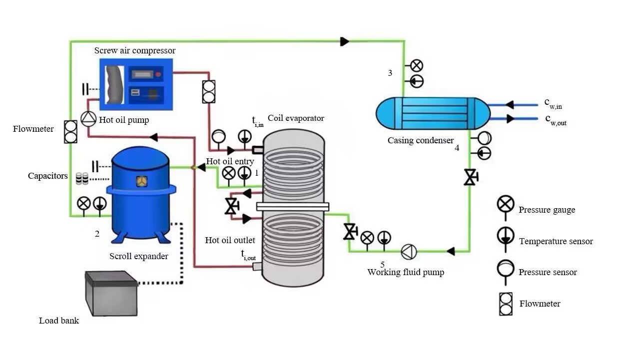
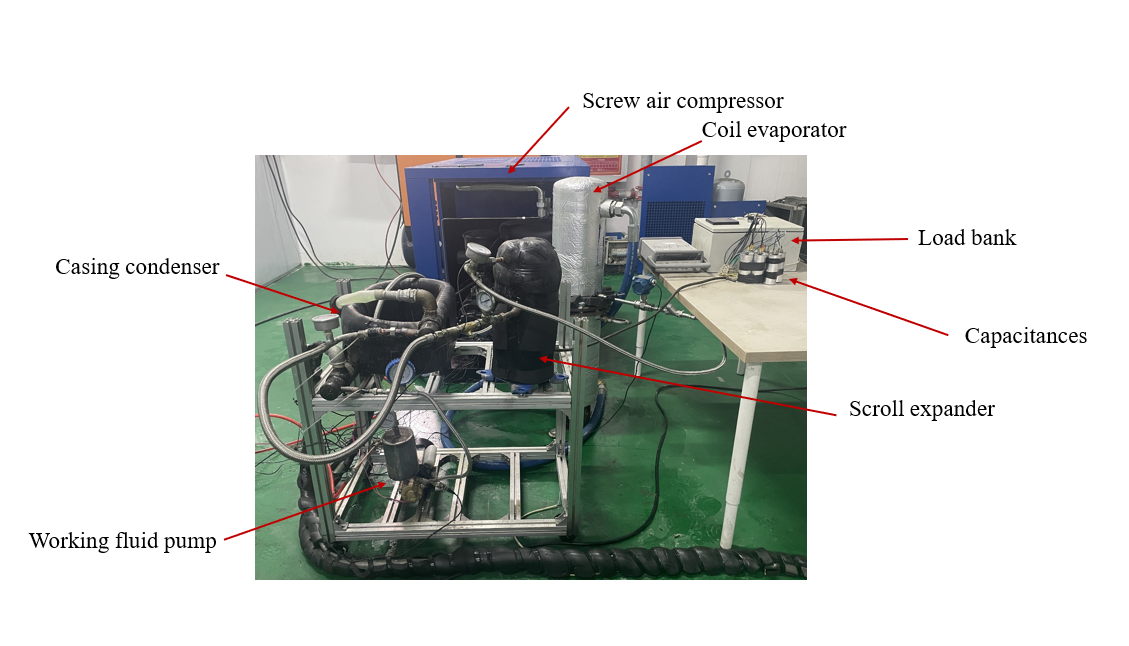
This study designed and constructed a screw air compressor–waste oil ORC integrated system experimental testing platform. Figure 1 presents the flow diagram and experimental setup of the system. As shown in Figure 1(a), the testing platform consists of three subsystems: the lubricating oil circulation subsystem of the screw air compressor, the ORC power generation subsystem, and the cooling water subsystem.
(a)
(b)
Figure 1. (a) Flow diagram of the screw air compressor–waste oil ORC integrated system testing platform; (b) experimental setup diagram
In the lubricating oil circulation subsystem, the lubricating oil is used to cool and lubricate the screw air compressor. Before operation, the oil level of the screw compressor must be maintained within a proper range. In traditional industrial screw compressors, air cooling is the most common method for dissipating residual heat from lubricating oil. In this system, the lubricating oil is pumped from the screw compressor to a coil-type evaporator, where it transfers heat to the working fluid in the ORC power generation subsystem. Therefore, the lubricating oil circuit (marked in red) acts as the heat source for the ORC power generation subsystem. The oil temperature is regulated by a thermostatic valve, while the flow rate is controlled by a flow valve. The physical properties of the lubricating oil are shown in Table 2.
The ORC power generation subsystem (green line) primarily consists of a working fluid pump, coil-type evaporator, scroll expander, load electrical box, capacitor, and shell-and-tube condenser. Considering the immature state of scroll expander technology, this system uses a hermetically sealed variable-frequency scroll compressor, structurally modified by Danfoss, as a scroll expander. The modifications include: (1) removing the internal check valve to allow high-pressure working fluid vapor to enter the chamber; (2) replacing the gear oil pump bearing with a centrifugal oil-lubricated bearing to enable reverse rotation of the shaft.
In the ORC power generation subsystem, the working fluid absorbs heat from the compressor’s lubricating oil in the coil-type evaporator and evaporates into superheated vapor. The high-pressure vapor enters the scroll expander to output mechanical power. The function of the capacitor in this study is as follows: since the scroll expander is retrofitted from a scroll compressor, the generator is an asynchronous generator. To enable the generator to operate off-grid, the capacitor provides the magnetic field necessary for the asynchronous motor to output power in an off-grid state. The capacitor is directly connected to the scroll expander to generate the magnetic field. The internal motor of the expander acts as a generator by cutting through the magnetic flux lines with its rotor. The magnetic field is produced by the current in the capacitor wire; as the current flows, the rotor cuts through the magnetic lines of flux. The stator receives the induced current generated by the rotor’s motion through the magnetic field. As current flows through the stator, it produces a stable rotating magnetic field that aids the rotor’s movement. The detailed process is illustrated in Figure 2. The low-pressure vapor then flows into the shell-and-tube condenser, where it is cooled into liquid form. Finally, the liquid working fluid is pressurized by the pump and sent into the evaporator, initiating the next working cycle.
The cooling water subsystem (blue line) is used to dissipate residual heat from the working fluid loop. In this circuit, cooling water is supplied by the facility’s tap water, with the flow rate adjusted via a ball valve installed in the PVC pipeline.
Table 2. Physical properties of lubricating oil
Model | Density (kg/m³) | Flash Point (°C) | Thermal Conductivity (W/(m·K)) | Specific Heat Capacity (J/(kg·K)) | Appearance |
L-QB300 | 868.5 | 226 | 0.458 | 2.2 | Transparent |
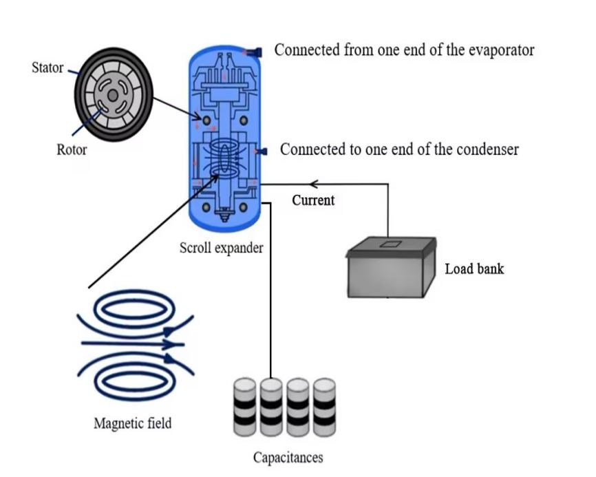
Figure 2. Power generation process of the ORC generator unit
2.3. Key components and data measurement
The main parameters of the experimental system components are shown in Table 3.
Table 3. Parameters of main components of the experimental system
Component | Model | Parameters |
Coil Evaporator | STB-1-32 | Coil volume: 25.3 L, heat exchange capacity: 32 kW, design pressure: 2.5 MPa |
Sleeve Condenser | R8HS051 | Heat exchange area: 0.68 m², heat exchange capacity: 15.8 kW |
Working Fluid Pump | SWK-750E | Rated power: 750 W, rated head: 65 m, weight: 5 kg, speed: 2800 r/min |
Scroll Expander | HRM051T4LP6 | AC voltage: 380 V ~ 415 V, operating frequency: 3~60 Hz |
Screw Air Compressor | JLY-50 | Rated power: 1080 kW, exhaust volume: 1.518 m³/min |
Thermal Oil Pump | RGP-30Y | Rated head: 30 m, speed: 2760 r/min, rated power: 2.2 kW |
Load Electrical Box | RCD-AC380V-10kW-RCD | Rated power: 1~10 kW, rated voltage: 380 V, frequency: 50 Hz |
Capacitor | CBB65 | Frequency: 50 Hz, capacitance: 150 μF |
To ensure the smooth progress of the experimental testing process, a system leak test must be conducted prior to testing. Nitrogen, an inert gas, is used as the test medium. The system pressure is maintained at a preset value of 1.6 MPa, and system sealing performance is assessed by observing pressure stability over a 48-hour period. If the pressure fluctuation remains within the permissible range, the system is considered to have good airtightness and meets the sealing requirements for the refrigerant. Meanwhile, the contact status of measuring elements at test points—such as flow meters, pressure sensors, and temperature probes—must be verified to ensure data acquisition accuracy.
The performance of the integrated system was investigated under various operating conditions. In the experiment, the inlet temperature of the lubricating oil at the coil evaporator was set to 75, 80, 85, 90, 95, 100, and 105 °C, respectively. Additionally, the cooling water temperature at the inlet of the sleeve condenser was set to 19, 27, and 30 °C. When the temperature fluctuation is controlled within ±0.3 °C, the integrated system is deemed to be in a stable state, and experimental data are recorded accordingly. A data acquisition cabinet was used to record temperature values continuously at a rate of four data points per minute. Pressure readings were recorded every five minutes, while current and voltage readings from the load group were recorded every 10 seconds. The detailed specifications of the measuring instruments are provided in Table 4.
Table 4. Measuring instrument parameters
Measuring Instrument | Model | Range | Accuracy |
Temperature Sensor | PT100 | -30 °C ~ 160 °C | ±0.15% |
Pressure Sensor | LU-THG06P1C | 0 ~ 50 MPa | ±0.1% |
Flow Meter | LKLWGY10MCSC | 1 ~ 150 m³/h | ±1% |
Load Electrical Box | FAJ96-3E | 0 ~ 20 A, 0 ~ 400 V | ±0.5% |
3. Theoretical thermal analysis of the system
Figure 3 illustrates the T-s diagram for the screw air compressor–residual oil ORC integrated system. As shown in Figure 3, the working fluid loop comprises four thermodynamic processes: heat absorption (5–1), expansion (1–2), condensation (2–4), and power dissipation during compression (4–5). The red and blue lines represent the temperature variations of the lubricating oil and cooling water, respectively. The system performance is evaluated using an energy analysis based on the First Law of Thermodynamics. For simplification, the following assumptions are made:
(1) All system components operate under steady-state and steady-flow conditions.
(2) Pressure losses in the evaporator and condenser are negligible.
(3) Changes in kinetic and potential energy of the working fluid are negligible.
(4) No pressure or heat loss occurs in the pipelines.
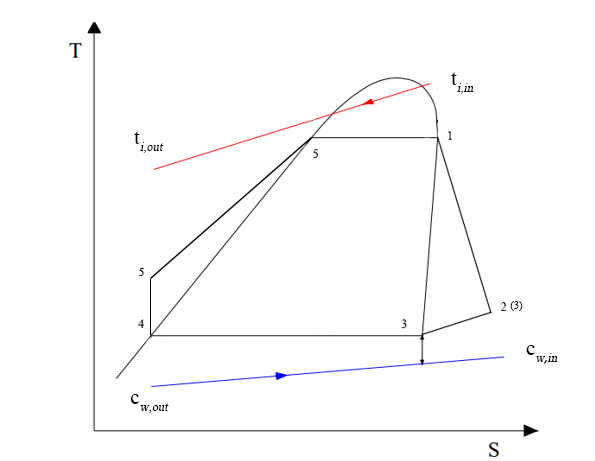
Figure 3. T-s diagram of the experimental system
3.1. Energy analysis method
The most commonly used indicators for evaluating the energy performance of an ORC power generation system are power output and thermoelectric efficiency. Power output refers to the electric power output of the ORC system during operation, indicating the system’s power generation capability. Thermoelectric efficiency is defined as the ratio of power output to the absorbed heat, reflecting the system’s thermal-to-electric energy conversion efficiency.
The heat released by the lubricating oil in the coiled evaporator (i.e., the heat absorbed by the working fluid) can be expressed as:
\( {Q_{i}}={m_{i}}×{c_{p,i}}×({t_{i,in}}-{t_{i,out}}) \) (1)
where: \( {m_{i}} \) is the mass flow rate of the lubricating oil, kg/s;
\( {c_{p,i}} \) is the specific heat capacity of the lubricating oil, J·kg⁻¹·K⁻¹;
\( {t_{i,in}} \) is the oil temperature at the evaporator inlet, K;
\( {t_{i,out}} \) is the oil temperature at the evaporator outlet, K.
The electrical output power of the scroll expander connected to the capacitor can be calculated by the following equation:
\( {W_{elc}}=\sqrt[]{3}{U_{ex}}{I_{ex}}cos{θ} \) (2)
where: \( {U_{ex}} \) is the line voltage of the scroll expander, V;
\( {I_{ex}} \) is the line current of the scroll expander, A;
\( cos{θ} \) represents the power factor, typically defined as the ratio of active power to apparent power, and is taken as 0.8.
The thermoelectric efficiency of the ORC power generation system is calculated as follows:
\( {η_{th}}=\frac{{W_{elc}}}{{Q_{i}}} \) (3)
3.2. Influence of lubricating oil temperature and flow rate
Figure 4 shows the variations in evaporation and condensation pressures under different lubricating oil temperatures. The results indicate that when the lubricating oil temperature at the evaporator inlet increases from 75 °C to 105 °C, the evaporation pressure rises from 0.714 MPa to 1.362 MPa. When the oil temperature is 75 °C, the evaporation pressure is 0.714 MPa. At oil temperatures of 80 °C, 85 °C, 90 °C, 95 °C, and 100 °C, the evaporation pressure increases by 15.49%, 8.54%, 16.85%, 9.61%, and 14.91%, respectively. This is because higher lubricating oil temperatures lead to higher evaporation temperatures, which in turn result in increased evaporation pressure. In contrast, the effect of lubricating oil on condensation pressure is minimal, since the condensation pressure is primarily determined by the condensation temperature (i.e., the cooling water temperature). When the cooling water temperature at the condenser inlet is 27 °C, the system’s condensation pressure is approximately 1.76 MPa.
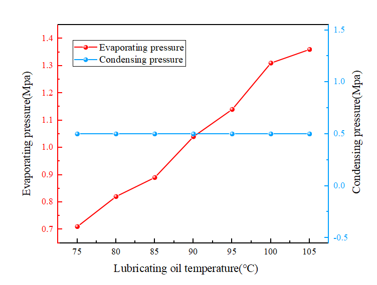
Figure 4. Evaporating and condensing pressure varying characteristics under different lubricating oil temperatures
Figure 5 illustrates the variations in line voltage (three-phase voltage) and line current (three-phase current) of the scroll expander with changing lubricating oil temperatures. As shown in Figure 5, when the oil temperature increases from 75 °C to 105 °C, the line voltage increases from 138.26 V to 276.68 V, and the line current rises from 2.251 A to 4.29 A. This is because the line current increases with the line voltage. The voltage operates within a range of 120 V to 280 V, with a maximum current of 4.29 A.
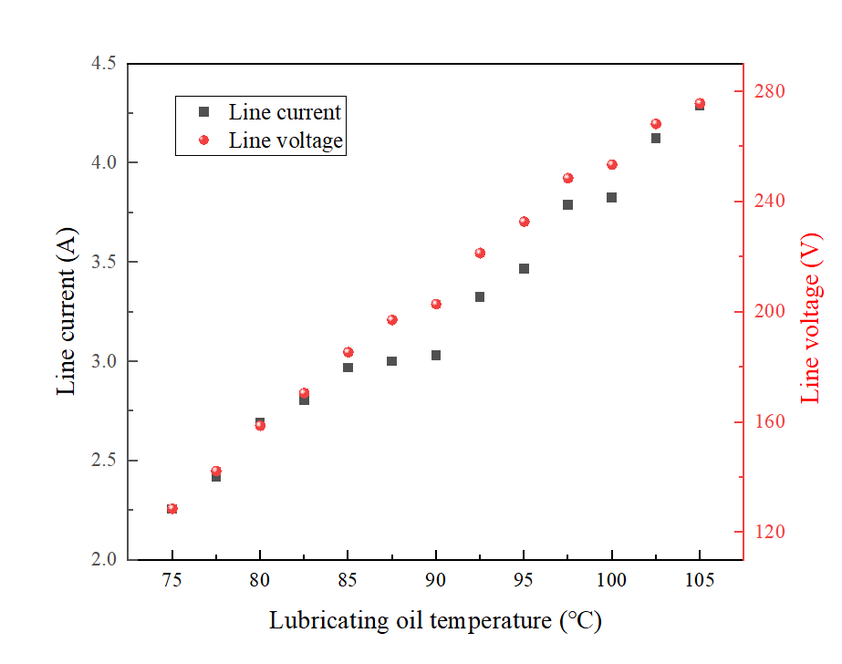
Figure 5. Electric parameter varying characteristics under different lubricating oil temperatures
Figure 6 illustrates the variation characteristics of power generation under different lubricating oil flow rates. According to Figure 6, the power output of the ORC power generation system increases with the rise in lubricating oil flow rate. When the flow rate reaches 12 m³/h, the growth rate of power output begins to slow down. At a lubricating oil inlet temperature of 95 °C, increasing the flow rate from 3 m³/h to 18 m³/h raises the power output from 0.634 kW to 1.151 kW, an increase of 44.91%. At inlet temperatures of 85 °C and 75 °C, the corresponding increases are 4.88% and 3.92%, respectively. For every 5 °C increase in lubricating oil temperature, the average increase in power output is 0.228 kW, with a growth rate of 26.43%. These results indicate that higher flow rates and temperatures lead to better power generation performance. The maximum power output of 1.151 kW is achieved when the lubricating oil temperature is 95 °C and the flow rate is 18 m³/h.
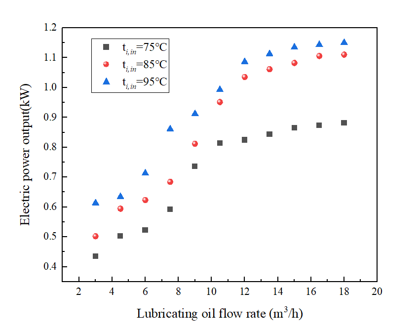
Figure 6. Power generation varying characteristics under different lubricating oil flow rates
The variation characteristics of thermal-to-electric efficiency under different lubricating oil flow rates are shown in Figure 7. It can be seen that the higher the lubricating oil flow rate, the higher the thermal-to-electric efficiency of the ORC power generation unit. When the lubricating oil temperature is maintained at 95 °C, increasing the flow rate from 3.02 m³/h to 18.92 m³/h improves thermal efficiency from 3.04% to 3.49%, an increase of 14.8%. For every 5 °C rise in lubricating oil temperature, thermal efficiency increases by approximately 6.67%. This result can be explained by the fact that a higher lubricating oil flow rate enhances heat transfer performance in the evaporator, thereby improving the thermal-to-electric efficiency of the ORC power generation system. A logarithmic relationship exists between lubricating oil flow rate and thermal efficiency. However, the effect of increasing the flow rate on improving thermal efficiency diminishes with higher flow rates. This implies that further increasing the flow rate beyond 12.05 m³/h yields no significant improvement in the thermal-to-electric efficiency of the ORC generator unit (based on the regression equation: ηth = 0.112ln(mi) + 2.456, ti,in=75℃). Additionally, the fitted equations at inlet temperatures of 85 °C and 95 °C are: ηth= 0.156ln(mi) + 2.684 (ti,in=85 ℃) and ηth= 0.123ln(mi) + 2.867 (ti,in=95 ℃), respectively.
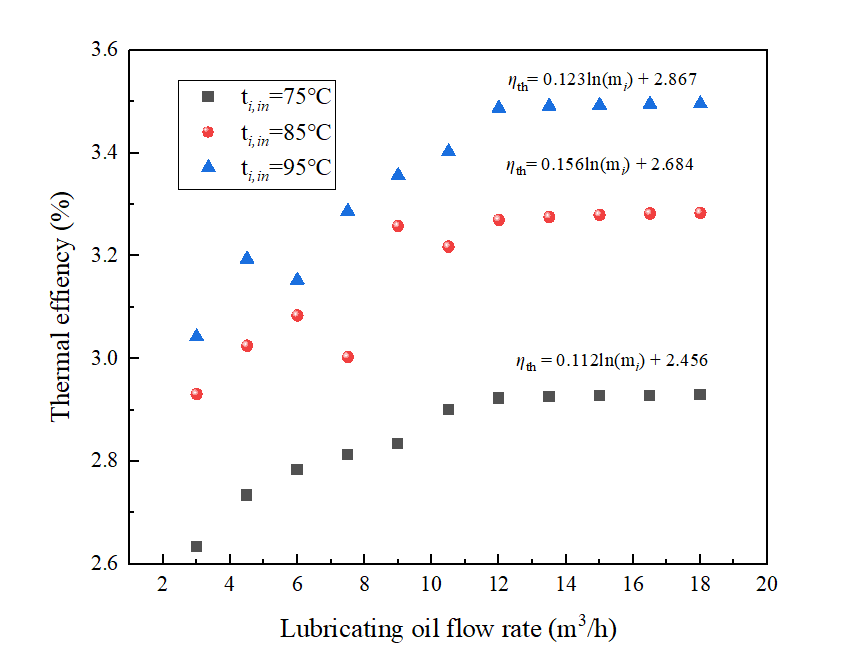
Figure 7. Thermal-to-electric efficiency varying characteristics under different lubricating oil flow rates
3.3. Influence of cooling water temperature
Figure 8 shows the variation in power output under different cooling water temperatures, with lubricating oil temperature ranging from 75 °C to 105 °C. As illustrated in Figure 8, an increase in the cooling water inlet temperature results in a decline in power output. When the cooling water inlet temperature increases from 19 °C to 30 °C, the power output decreases from 0.6347 kW to 0.4832 kW, a reduction of 23.9%. At a cooling water inlet temperature of 19 °C, the average power output is 1.066 kW. The maximum power output of 1.754 kW is achieved when the lubricating oil temperature is 105 °C and the cooling water temperature is 19 °C. At cooling water inlet temperatures of 27 °C and 30 °C, as the lubricating oil temperature increases from 75 °C to 105 °C, power output rises by 19.49% and 33.19%, respectively. On average, for every 5 °C increase in cooling water inlet temperature, the power output decreases by 0.159 kW, a reduction of 20.62%. Compared with cooling water temperature, lubricating oil temperature generally has a more significant impact on power output. Increasing the heat source temperature directly enhances the heating power provided by the lubricating oil, thereby more effectively improving power output. As a result, power output is more sensitive to changes in lubricating oil temperature than to cooling water temperature.
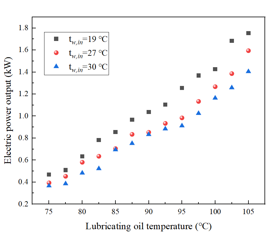
Figure 8. Power generation varying characteristics under different cooling water temperatures
Figure 9 displays the variation in thermal-to-electric efficiency under different cooling water temperatures. As shown in Figure 9, the lower the cooling water temperature, the higher the thermal efficiency of the ORC generator unit. A strong linear correlation exists between these two parameters. When the cooling water temperature increases from 19 °C to 30 °C and the lubricating oil temperature is 80 °C, the thermal efficiency drops sharply from 3.13% to 2.7%. On average, for every 5 °C increase in cooling water temperature, thermal efficiency decreases by 4.23%. When the lubricating oil temperature is 75 °C and 105 °C, the thermal efficiency ranges from 2.56% to 3.01% and from 3.58% to 3.91%, respectively. The system achieves a maximum thermal efficiency of 3.91% when the cooling water temperature is 19 °C and the lubricating oil temperature is 105 °C.
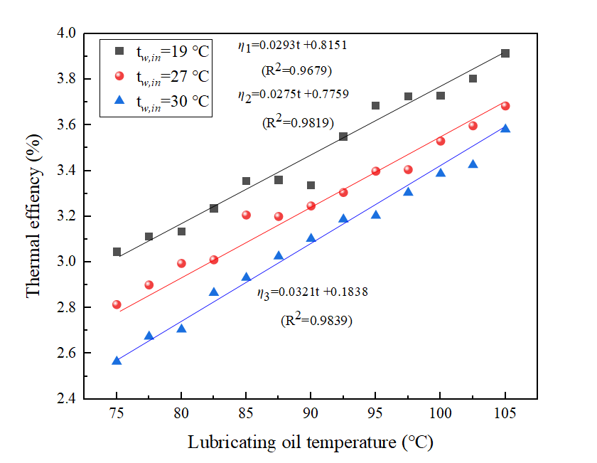
Figure 9. Thermal-to-electric efficiency varying characteristics under different cooling water temperatures
3.4. Effect of expander access capacitance
Figure 10 illustrates the variation in power generation characteristics under different capacitance values connected to the expander. As shown in Figure 10, the higher the capacitance connected to the expander, the greater the power output of the ORC power generation system. When the capacitance increases from 150 μF to 900 μF, the power output at a lubricating oil temperature of 75 °C rises from 0.389 kW to 1.361 kW, an increase of 59.4%. At a capacitance of 900 μF and a lubricating oil temperature of 105 °C, the maximum power output reaches 1.667 kW. The increase in capacitance enhances energy storage capacity, allowing more energy to be released in a short time, thereby improving electrical output. Therefore, the combined effect of increased capacitance and elevated lubricating oil temperature leads to enhanced power generation performance.
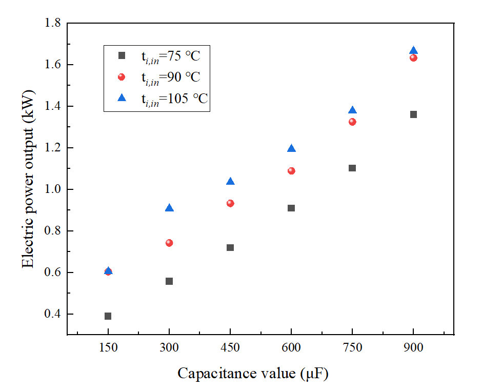
Figure 10. Power generation varying characteristics under different expander access capacitance values
Figure 11 presents the variation in thermal-to-electric efficiency under different expander access capacitance values. It is evident that the thermal-to-electric efficiency of the ORC power generation system improves with increased capacitance. When the capacitance rises from 150 μF to 900 μF at a lubricating oil temperature of 75 °C, the thermal-to-electric efficiency increases from 2.065% to 3.499%, representing an improvement of 40.91%. When the lubricating oil temperature is 75 °C, 90 °C, and 105 °C respectively, each 150 μF increase in capacitance leads to corresponding efficiency improvements of 20.1%, 24.5%, and 27.3%. The maximum thermal-to-electric efficiency of 3.66% is achieved at a capacitance of 900 μF and a lubricating oil temperature of 105 °C.
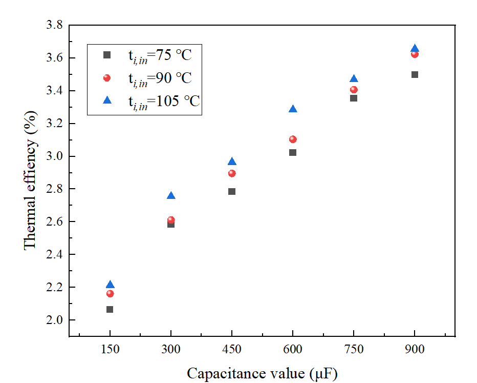
Figure 11. Thermal-to-electric efficiency varying characteristics under different expander access capacitance values
4. Conclusion
Based on the established test platform for the compact screw air compressor–oil residue ORC integrated system, multiple performance tests were conducted under various operating conditions. By studying and evaluating its energy performance, the feasibility and reliability of the integrated system were verified. The following conclusions can be drawn:
(1) For approximately every 5 °C increase in lubricating oil temperature (from 75 °C to 95 °C), the ORC power generation system’s power output and thermal-to-electric efficiency increase on average by 0.228 kW and 6.67%, respectively. The enhancement effect of increasing lubricating oil flow rate diminishes as the flow increases. Raising the lubricating oil flow from 12.05 m³/h (in this study, corresponding to 12.05 m³/h, 13.26 m³/h, and 13.68 m³/h at 75 °C, 85 °C, and 95 °C respectively) to even higher levels have minimal impact on improving the system’s thermal-to-electric efficiency.
(2) For every 5 °C increase in cooling water temperature (from 19 °C to 30 °C), the average power output and thermal-to-electric efficiency of the ORC power generation unit decrease by 0.159 kW and 4.23%, respectively. Thus, the thermal source temperature has a greater impact on the thermal performance of the ORC power generation system than the cold source temperature. When the cooling water temperature is 19 °C and the lubricating oil temperature is 105 °C, the maximum power output and thermal-to-electric efficiency of the ORC power generation unit reach 1.754 kW and 3.91%, respectively.
(3) Increasing the capacitance connected to the expander can improve the energy performance of the ORC power generation system and further enhance the overall thermal-to-electric efficiency of the integrated system. At a capacitance value of 900 μF and a lubricating oil temperature of 105 °C, the maximum power output and thermal-to-electric efficiency of the ORC power generation system reach 1.667 kW and 3.66%, respectively.
Funded project
Central Guiding Funds for Local Science and Technology Development Projects (236Z4503G); Industry-University-Research Collaboration Projects of Shijiazhuang in Hebei Province (241010071A); Colleges and Universities in Hebei Province Science Research Fund (CXZX2025025)
References
[1]. Chovancová, J., Petruška, I., Pata, U. K., Adamišin, P. (2025). Diverse pathways to decarbonization: Cluster-specific impacts of energy sources on CO₂ emissions in the European Union. Energy Nexus, 17.
[2]. Gao, J., Wang, H., & Sharma, M. (2024). Research progress and prospects of CO₂ fracturing for developing unconventional energy sources. Geoenergy Science and Engineering, 241.
[3]. Supaokit, A., Verma, V., Wang, W.-C., Chen, C.L., Wang, M.-S., Nugroho, R.A.-A., Duong, V.-D., Hsu, W.-H. (2025). Turning CO₂ into an alternative energy source: Study on methanation reaction optimization. Applied Catalysis A: General, 691.
[4]. Xia, C., Balsalobre-Lorente, D., & Raza Syed, Q. (2025). Electricity generation from renewable and non-renewable energy sources in China: The role of environmental policy stringency, FDI, and economic growth. Energy, 318.
[5]. Chen, X. H., Tee, K., Elnahass, M., Ahmed, R. (2023). Assessing the environmental impacts of renewable energy sources: A case study on air pollution and carbon emissions in China. Journal of Environmental Management, 345.
[6]. Srivastava, M., Sarkar, J., Sarkar, A., Maheshwari, N.K., Antony, A. (2024). Thermo-economic feasibility study to utilize ORC technology for waste heat recovery from Indian nuclear power plants. Energy, 298.
[7]. Zhang, Q., Feng, Y.-Q., Xu, K.-J., Liang, H.-J., Liu, Z.-N., Zhao, C.-Y., Wang, Y.-Z., Sapin, P., Markides, C.N. (2024). Dynamic behaviour and performance evaluation of a biomass-fired organic Rankine cycle combined heat and power (ORC-CHP) system under different control strategies. Applied Thermal Engineering, 248.
[8]. Permana, D. I., Mahardika, M. A., Rusirawan, D., Farkas, I. (2024). Utilization of small solar ORC integrated with phase change material in Indonesia condition. Journal of Energy Storage, 92.
[9]. Lei, B., Wang, J.-F., Wu, Y.-T., Ma, C.-F., Wang, W., Zhang, L., Li, J.-Y. (2016). Experimental study and theoretical analysis of a Roto-Jet pump in small scale organic Rankine cycles. Energy Conversion and Management, 111, 198–204.
[10]. Zakeralhoseini, S., & Schiffmann, J. (2023). Design, computational and experimental investigation of a small-scale turbopump for organic Rankine cycle systems. Energy Conversion and Management, 287.
[11]. Wronski, J., Imran, M., Skovrup, M. J., Haglind, F. (2019). Experimental and numerical analysis of a reciprocating piston expander with variable valve timing for small-scale organic Rankine cycle power systems. Applied Energy, 247, 403–416.
[12]. Tsai, Y.-C., Feng, Y.-Q., Shuai, Y., Lai, J.-H., Leung, M.K.H., Wei, Y., Hsu, H.-Y., Hung, T.-C. (2023). Experimental validation of a 0.3 kW ORC for the future purposes in the study of low-grade thermal to power conversion. Energy, 285.
[13]. Jiang, L., Wang, R. Q., & Roskilly, A. P. (2020). Techno-economic analysis on a small-scale organic Rankine cycle with improved thermal driven pump. Energy Conversion and Management, 217.
[14]. Xiao, M., Zhou, Y., Miao, Z., Yan, P., Zhang, M., Xu, J. (2024). Multi-condition operating characteristics and optimization of a small-scale ORC system. Energy, 290.
[15]. Colak, A. B., & Arslan, O. (2024). Numerical analysis-based performance assessment of the small-scale organic Rankine cycle turbine design for residential applications. Thermal Science and Engineering Progress, 51.
[16]. Shen, J., Li, Z., Tan, N., Xiao, Y. (2022). Design and analysis of a suction pretreatment system for the air compressor. Energy Conversion and Management, 263.
[17]. Murgia, S., Valenti, G., Colletta, D., Costanzo, I., Contaldi, G. (2017). Experimental investigation into an ORC-based low-grade energy recovery system equipped with sliding-vane expander using hot oil from an air compressor as thermal source. In Proceedings of the 4th International Seminar on ORC Power Systems (ORC) (pp. 13–15). Politecnico Milano Bovisa Campus.
[18]. Valenti, G., Valenti, A., & Staboli, S. (2019). Proposal of a thermally-driven air compressor for waste heat recovery. Energy Conversion and Management, 196, 1113–1125.
Cite this article
Yu,X.;Shao,Y.;Li,S. (2025). Performance study of an integrated system combining a small-scale Organic Rankine Cycle power generation unit and an air compressor for waste heat recovery. Advances in Engineering Innovation,16(6),10-20.
Data availability
The datasets used and/or analyzed during the current study will be available from the authors upon reasonable request.
Disclaimer/Publisher's Note
The statements, opinions and data contained in all publications are solely those of the individual author(s) and contributor(s) and not of EWA Publishing and/or the editor(s). EWA Publishing and/or the editor(s) disclaim responsibility for any injury to people or property resulting from any ideas, methods, instructions or products referred to in the content.
About volume
Journal:Advances in Engineering Innovation
© 2024 by the author(s). Licensee EWA Publishing, Oxford, UK. This article is an open access article distributed under the terms and
conditions of the Creative Commons Attribution (CC BY) license. Authors who
publish this series agree to the following terms:
1. Authors retain copyright and grant the series right of first publication with the work simultaneously licensed under a Creative Commons
Attribution License that allows others to share the work with an acknowledgment of the work's authorship and initial publication in this
series.
2. Authors are able to enter into separate, additional contractual arrangements for the non-exclusive distribution of the series's published
version of the work (e.g., post it to an institutional repository or publish it in a book), with an acknowledgment of its initial
publication in this series.
3. Authors are permitted and encouraged to post their work online (e.g., in institutional repositories or on their website) prior to and
during the submission process, as it can lead to productive exchanges, as well as earlier and greater citation of published work (See
Open access policy for details).
References
[1]. Chovancová, J., Petruška, I., Pata, U. K., Adamišin, P. (2025). Diverse pathways to decarbonization: Cluster-specific impacts of energy sources on CO₂ emissions in the European Union. Energy Nexus, 17.
[2]. Gao, J., Wang, H., & Sharma, M. (2024). Research progress and prospects of CO₂ fracturing for developing unconventional energy sources. Geoenergy Science and Engineering, 241.
[3]. Supaokit, A., Verma, V., Wang, W.-C., Chen, C.L., Wang, M.-S., Nugroho, R.A.-A., Duong, V.-D., Hsu, W.-H. (2025). Turning CO₂ into an alternative energy source: Study on methanation reaction optimization. Applied Catalysis A: General, 691.
[4]. Xia, C., Balsalobre-Lorente, D., & Raza Syed, Q. (2025). Electricity generation from renewable and non-renewable energy sources in China: The role of environmental policy stringency, FDI, and economic growth. Energy, 318.
[5]. Chen, X. H., Tee, K., Elnahass, M., Ahmed, R. (2023). Assessing the environmental impacts of renewable energy sources: A case study on air pollution and carbon emissions in China. Journal of Environmental Management, 345.
[6]. Srivastava, M., Sarkar, J., Sarkar, A., Maheshwari, N.K., Antony, A. (2024). Thermo-economic feasibility study to utilize ORC technology for waste heat recovery from Indian nuclear power plants. Energy, 298.
[7]. Zhang, Q., Feng, Y.-Q., Xu, K.-J., Liang, H.-J., Liu, Z.-N., Zhao, C.-Y., Wang, Y.-Z., Sapin, P., Markides, C.N. (2024). Dynamic behaviour and performance evaluation of a biomass-fired organic Rankine cycle combined heat and power (ORC-CHP) system under different control strategies. Applied Thermal Engineering, 248.
[8]. Permana, D. I., Mahardika, M. A., Rusirawan, D., Farkas, I. (2024). Utilization of small solar ORC integrated with phase change material in Indonesia condition. Journal of Energy Storage, 92.
[9]. Lei, B., Wang, J.-F., Wu, Y.-T., Ma, C.-F., Wang, W., Zhang, L., Li, J.-Y. (2016). Experimental study and theoretical analysis of a Roto-Jet pump in small scale organic Rankine cycles. Energy Conversion and Management, 111, 198–204.
[10]. Zakeralhoseini, S., & Schiffmann, J. (2023). Design, computational and experimental investigation of a small-scale turbopump for organic Rankine cycle systems. Energy Conversion and Management, 287.
[11]. Wronski, J., Imran, M., Skovrup, M. J., Haglind, F. (2019). Experimental and numerical analysis of a reciprocating piston expander with variable valve timing for small-scale organic Rankine cycle power systems. Applied Energy, 247, 403–416.
[12]. Tsai, Y.-C., Feng, Y.-Q., Shuai, Y., Lai, J.-H., Leung, M.K.H., Wei, Y., Hsu, H.-Y., Hung, T.-C. (2023). Experimental validation of a 0.3 kW ORC for the future purposes in the study of low-grade thermal to power conversion. Energy, 285.
[13]. Jiang, L., Wang, R. Q., & Roskilly, A. P. (2020). Techno-economic analysis on a small-scale organic Rankine cycle with improved thermal driven pump. Energy Conversion and Management, 217.
[14]. Xiao, M., Zhou, Y., Miao, Z., Yan, P., Zhang, M., Xu, J. (2024). Multi-condition operating characteristics and optimization of a small-scale ORC system. Energy, 290.
[15]. Colak, A. B., & Arslan, O. (2024). Numerical analysis-based performance assessment of the small-scale organic Rankine cycle turbine design for residential applications. Thermal Science and Engineering Progress, 51.
[16]. Shen, J., Li, Z., Tan, N., Xiao, Y. (2022). Design and analysis of a suction pretreatment system for the air compressor. Energy Conversion and Management, 263.
[17]. Murgia, S., Valenti, G., Colletta, D., Costanzo, I., Contaldi, G. (2017). Experimental investigation into an ORC-based low-grade energy recovery system equipped with sliding-vane expander using hot oil from an air compressor as thermal source. In Proceedings of the 4th International Seminar on ORC Power Systems (ORC) (pp. 13–15). Politecnico Milano Bovisa Campus.
[18]. Valenti, G., Valenti, A., & Staboli, S. (2019). Proposal of a thermally-driven air compressor for waste heat recovery. Energy Conversion and Management, 196, 1113–1125.