


1. MIMO Systems
1.1 Technology Principles
For conventional wireless communication systems, multipath transmission in the channel produces fading, whereas communication systems take advantage of this disadvantage caused by multipath transmission and classify it as an advantage to be exploited. It can be found that the system is equipped with multiple antennas at both the receiving and transmitting ends, the serial data stream at the transmitting end is sent to the corresponding antenna for transmission after some necessary processing, the transmitted data passes through the wireless channel and is received by the receiving end, where it is then processed using various air-time detection techniques to recover the original signal. In order to separate the sub-streams at the receiving end, we need to minimise the correlation between the received signals, and for this reason the antennas are usually located more than half a carrier away from each other. Unlike the smart antenna case, wireless channels that are independent of each other or have little correlation exist between any transceiver antenna pair of the system. Since the data sub-streams of the system send symbols to the channel simultaneously while sharing the same frequency band, there is no increase in the bandwidth of the system [1]. If the transceiver antenna pairs have response channels that are independent of each other, the data rate of the system can be significantly improved by reducing the system to multiple parallel subspace channels.
In the MIMO system shown, the transmitter is equipped with N wires and the receiver with M antennas. Using xi (t), (i=1, 2, ..., NT), denoting the information transmitted by the ith transmitting antenna, and yj (t), (j=1, 2, ..., NR) to denote the information received by the jth receive antenna, and assuming that the channel obeys a Rayleigh distribution, the sub-channel of the MIMO system can thus be represented as:
 (1)
(1)
The symbol denotes the transpose of a vector or matrix, similarly the signal on the receiving antenna array can be expressed as.
 (2)
(2)
And the channel impulse response of the MIMO channel between the transmitter and receiver can be expressed as.
 (3)
(3)
where the complex matrix
 (4)
(4)
is the channel impulse response matrix corresponding to the time delay T, and is the complex gain of the sub-channel between the nth transmitting antenna and the mth receiving antenna, Eqs. (1-3) represent a simple model of a tapped delay line, although here the channel coefficients of the L time delays are expressed in terms of matrices, for the MIMO system shown in Fig. 1.1 the transmitting signal vector s(t) and the receiving signal vector r(k) The relationship between them can be expressed as:
 (5)
(5)
1.2 System modelling
We consider a MIMO system with a transmitting array of antennas and a receiving array of
 antennas. Figure 1 shows a sketch of such a system [2].
The transmit matrix is a × 1 column matrix s. Here
 is the ith element, transmitted from the ith antenna. We consider the channel to be Gaussian, such that the elements in s are considered to be independently and identically distributed Gaussian functions. If the channel is known at the transmitter side, we assume that the transmitted signal from each antenna has equal power /
 . The covariance distance array of this transmitted signal is given by the following equation:
 (6)
(6)
Here is the power passing through the transmitter without taking into account the number of transmitter antennas
 , and
, and is a
is a ×
× unit matrix. The bandwidth of the transmitted signal is so narrow that its frequency response can be considered flat. (The channel is memoryless). The channel matrix H is a
 ×
× sum matrix. The
 element of the matrix is the attenuation coefficient from the ith transmitting antenna to the jth receiving antenna. We assume that the received power of each receive antenna is equal to the total transmit power
 . This means that we can ignore signal attenuation, array gain, and so on. In this way we normalise the constraints on the H matrix elements that determine the channel with Eq7.
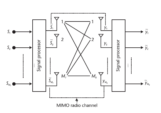
Figure 1. Sketch of the MIMO system
 (7)
(7)
If the channel elements are not deterministic but random, normalisation will apply to the expectations of Eq7. We assume that the channel is known at the receiving end but not at the transmitting end. The channel matrix can be estimated at the receiving end by firing a training sequence. If we require the channel to be known at the transmitter, we need to communicate this information to the transmitter through a feedback channel. The elements of the H-array can be either deterministic or random. The noise at the receiving end is another × 1 column matrix, denoted by n. The elements of n are zero-mean circularly symmetric complex Gaussian variables. The covariance distance matrix of the receiver noise is:
 (8)
(8)
If there is no correlation between the elements n, the covariance distance matrix is:
 (9)
(9)
Each receiving branch has equal noise power
 . The receiver applies the maximum likelihood criterion to the
 receiving antennas. The received signals form a
 × 1 column matrix, denoted r, with each complex element corresponding to a receiving antenna. Since we assume that the total received power of each antenna is equal to the total transmitted power, the signal-to-noise ratio can be expressed by the following equation:
 (10)
(10)
Therefore, the receiving vector can be expressed as:
 (11)
(11)
The covariance matrix of the received signal is defined as from equation 2.6:
 (12)
(12)
Also, the total signal power can be expressed as
2. VBLAST system
2.1 Introduction to Hierarchical Space Time Codes
Layered Space-Time codes (LST: Layered Space-Time codes) were originally proposed by Foschini of Bell Labs, and hence are also known as BLAST (Bell Labs Layered Space-Time). As a solution for experimentally telling wireless packet services in MIMO systems, Layered Space-Time codes have attracted much attention due to their great potential for improving band utilisation [3].
Layered space-time codes, together with space-time packet codes and space-time grid codes, belong to a class of space-time codes that require the receiver to be able to estimate the channel accurately. Compared with the latter two, hierarchical airtime codes sacrifice some diversity gain for high-frequency band utilisation. If the receiver can accurately estimate the channel information and ensure that different transmitter and receiver antennas are independent of each other, for a system with N transmitter antennas and M receiver antennas, the channel capacity that can be achieved by hierarchical space-time codes will increase linearly with the increase of min(N,M). The hierarchical space-time code is the only known coding method in which the band utilisation increases linearly with the number of antennas. This gives it a great advantage for applications in high-speed wireless communications [4].
The basic idea of layered space-time coding technique is: at the transmitter side, the high-speed data service is divided into a number of low-speed data service streams, which are encoded by an ordinary parallel channel coder and then subjected to layered space-time coding, and then sent with multiple antennas after modulation; at the receiver side, it is received with multiple antennas in a diversity of receivers and the accurate channel parameters are obtained through good channel estimation, and the layered judgement feedback is achieved by the linear judgement feedback equalizer interference cancellation, then hierarchical space-time decoding, and finally a single channel decoder to complete the channel decoding work [5].
The channel is assumed to be a narrowband, quasi-static, flat Rayleigh fading MIMO channel environment. Due to the main emphasis on the signal processing part, all signal forms in the following analysis are baseband digital signals.
In a certain time interval transmitting antenna k (k=1,2,... ,N) to the receiving antenna l(l =1,2,... ,M) The channel gain between is denoted as hkl , hkl is a complex Gaussian random variable obeying a mean of 0 and variance of 1. Denote H=(hkl ) as the channel matrix. The received signal from the receiving antenna l is rl (l=1,2,...,M), then rl is the sum of the superposition of the signals ck (k=1,2,...,N) transmitted by N transmitting antennas with Gaussian white noise.
Denote the column vector:
 (2.1)
(2.1)
Then there is:
 (2.2)
(2.2)
Here, nl (l=1,2,...,M) is the additive Gaussian white noise (AWGN) for each receiving antenna. When the number of receiving antennas, M is larger than the number of transmitting antenna books N, the system capacity grows proportionally to the transmitting antenna book N. The advantage of the hierarchical space-time code is that
 (2.3)
(2.3)
where ρ is the average received signal-to-noise ratio of each receiving antenna.
2.2 Hierarchical space-time code coding principle
Four different hierarchical space-time coding schemes usually exist for signals sent from N parallel channel coders: horizontal layered space-time coding (HLST); vertical layered space-time coding (VLST); diagonal layered space-time coding (DLST); and spiral layered space-time coding (TLST). In the following, it introduces the coding scheme of horizontal and vertical layered space-time codes.
The horizontal hierarchical space-time encoder accepts the output of the parallel channel coder and then spatially encodes it according to the horizontal direction, i.e., the coded code elements of each channel coder are directly fed to the corresponding antenna (the channel coder and the antenna are one-to-one) for transmitting.
The vertically layered space-time code encoder receives the output of the parallel channel coder and then spatially encodes it according to the vertical direction.
The very first first N code elements output by the 1st channel coder are arranged in the first column, the very first first N code elements output by the 2nd channel coder are arranged in the second column, and the jth batch of N code elements output by the i-th channel coder are arranged in the (i+(j-1)N) column. Each column in the matrix of encoded airtime code elements is transmitted simultaneously via N transmitting antennas, respectively.
3. V-BLAST System Detection Algorithm
Linear detection requires that the number of receiving antennas in a MIMO system is not lower than the number of transmitting antennas; otherwise, for linear detection algorithms, better detection performance cannot be obtained even in the absence of noise. Currently, the main linear detection algorithms include the forced zero (ZF) algorithm and the minimum mean square error (MMSE) algorithm, the difference between the two is that the weighting criterion is different. Linear detection algorithms have lower complexity and are easy to implement, but the detection performance is also relatively poor. Both the ZF algorithm and the MMSE algorithm are essentially the inverse of the channel matrix, and in order to make the inverse of the channel matrix have a unique solution, it is necessary to require that the number of receiving antennas is not less than the number of transmitting antennas, i.e., M>N.
3.1 ZF Linear Detection Algorithm.
For the ZF detection algorithm, since the signal received by each pair of antennas at the receiving end of the MIMO system is an amalgamation of multiple transmitted signals, which results in signal interference, the ZF algorithm is to completely eliminate the interference between the signals.
Using the ZF algorithm, the linear weighting matrix for the detection of the signal at the receiver is.

Left-multiplying the received signal r by the linear weighting matrix at the receiving end gives.


3.2 ZF linearly ordered serial interference cancellation detection algorithm.
The full ZF detection algorithm is a recursive process that includes a judgement of the best ordering:
Initial value setting:

Recursion:


3.3 MMSE linear detection algorithm.
The ZF algorithm removes interference from other sub-streams but does so at the cost of amplifying the noise.The MMSE algorithm is also a linear detection technique, where the stage assigns different weights to each of the received sub-streams based on some performance criterion, and the difference between the two lies in the difference in the strategy of determining the weights based on the received signals and the channel matrices.
In the MMSE detection algorithm, the mean value of the mean square error between a linear combination of the transmit vector s and the receive vector is minimised, i.e.
 minimises
Among them:

where is an M*N matrix of linear joint coefficients, i.e., it is the matrix of weight vectors: e.g., σ2 the noise variance, and IN is an N× N unit array, and [HH H + σ I ]2N+ is the generalised inverse matrix of the matrix [HH H + σ I2N ].
3.4 MMSE sequential serial interference cancellation detection algorithm.
Suppose that the detection order is , which is a permutation of the integers 1,2,..., M .
Initial value setting:


Recursion:


4. Conclusion
Experimentally simulated the error bit rate of VBLAST in in BPSK,modulation mode, channel correlation coefficient is 0 respectively, the number of simulation is 150,000, and its simulation results are shown in the figure below.
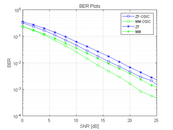
Figure 2. Comparison of error bit rate of four detection methods
There are simulation graphical comparisons that show that MM-OSIC has the best detection performance, the algorithm using sequential serial interference cancellation has better performance than the original algorithm, and the minimum mean square error detection algorithm has better detection performance than the broken zero detection algorithm.
References
[1]. Jian Zhang, Research of the MIMO system combining STBC and VBLAST, 5.2006
[2]. XUE TING, The Research of Detection Algorithms in MIMO Spatial Multiplex System, May. 2013
[3]. Wang Hong-xiang, An Improved Detection Algorithms in VBLAST System, Journal of Chongqing Institute of Science and Technology, 4. Vol.13, Aug. 2011
[4]. Wang Hong Hai, A Near Optimal List Detection Algorithm in VBLAST Systems, Signal Processing, 7.Vol.26, July.2010
[5]. Foschini G J.Layered space-time architecture for wireless communication in fading environment when using multiple antennas[J]. Bell Lab Technical Journal, 1996, 1(2): 41-59
Cite this article
Wang,Y. (2023). Broadband wireless access and IP technologies - VBLAST detection algorithm. Advances in Engineering Innovation,1,1-9.
Data availability
The datasets used and/or analyzed during the current study will be available from the authors upon reasonable request.
Disclaimer/Publisher's Note
The statements, opinions and data contained in all publications are solely those of the individual author(s) and contributor(s) and not of EWA Publishing and/or the editor(s). EWA Publishing and/or the editor(s) disclaim responsibility for any injury to people or property resulting from any ideas, methods, instructions or products referred to in the content.
About volume
Journal:Advances in Engineering Innovation
© 2024 by the author(s). Licensee EWA Publishing, Oxford, UK. This article is an open access article distributed under the terms and
conditions of the Creative Commons Attribution (CC BY) license. Authors who
publish this series agree to the following terms:
1. Authors retain copyright and grant the series right of first publication with the work simultaneously licensed under a Creative Commons
Attribution License that allows others to share the work with an acknowledgment of the work's authorship and initial publication in this
series.
2. Authors are able to enter into separate, additional contractual arrangements for the non-exclusive distribution of the series's published
version of the work (e.g., post it to an institutional repository or publish it in a book), with an acknowledgment of its initial
publication in this series.
3. Authors are permitted and encouraged to post their work online (e.g., in institutional repositories or on their website) prior to and
during the submission process, as it can lead to productive exchanges, as well as earlier and greater citation of published work (See
Open access policy for details).
References
[1]. Jian Zhang, Research of the MIMO system combining STBC and VBLAST, 5.2006
[2]. XUE TING, The Research of Detection Algorithms in MIMO Spatial Multiplex System, May. 2013
[3]. Wang Hong-xiang, An Improved Detection Algorithms in VBLAST System, Journal of Chongqing Institute of Science and Technology, 4. Vol.13, Aug. 2011
[4]. Wang Hong Hai, A Near Optimal List Detection Algorithm in VBLAST Systems, Signal Processing, 7.Vol.26, July.2010
[5]. Foschini G J.Layered space-time architecture for wireless communication in fading environment when using multiple antennas[J]. Bell Lab Technical Journal, 1996, 1(2): 41-59