


1. Introduction
FDM, which stands for Fused Deposition Modeling, is a common additive manufacturing technique. It involves heating and melting a thermoplastic filament that is then deposited layer by layer onto a building platform using a nozzle, creating a three-dimensional object [1]. FDM technology is relatively simple and does not require expensive components such as a laser. It is easier to operate and maintain and has virtually no restrictions on the usage environment. It can be placed in an office or home for use. The raw materials are provided as filament spools, which are easy to transport and replace quickly. Additionally, FDM printers are relatively affordable in price. Thus, FDM has become the most common technology in commercial use. Since in FDM, 2.5-axis printing is a common method, which allows movement in the X and Y directions but cannot print vertically along the Z-axis, support structures are required to address the challenges posed by overhangs or cantilevered structures. These support structures temporarily support the overhanging sections of the printed object during the printing process, ensuring stability to prevent deformation. Therefore, many supports are necessary for some printing models due to the disadvantage of 2.5-axis printing.
Traditional support methods include grid support, columnar support, tree support, etc. [2, 3]. These support methods are simple to use and can be quickly formed. However, traditional support methods also have the issue of material wastage. Traditional support structures typically require a significant amount of support material, which increases material consumption and waste. Particularly for large and complex printed objects, the support structures can consume considerable material, increasing costs. Traditional support designs often result in material waste and increased costs while limiting the improvement of manufacturing speed and efficiency [4]. In Schmidt and Umetani’s research, they designed a branch-like support structure and proved that branch-like support could decline the printing time cost and reduce a large amount of material use [5, 6]. However, they did not determine the support strength. Thus, a specific new support structure is waiting to be found, and certain properties are needed for measurement. Considering the structural advantages of truss systems, characterized by high strength and minimal material consumption, this research aims to design a simple truss structure and then compare and analyze column support with truss support by controlling variables. The objective is to demonstrate the potential application of truss support structures in 2.5-axis printing.
2. Overview of truss structure
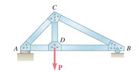
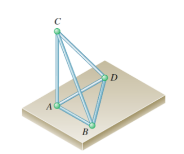
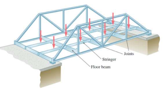
The truss is one of the major types of engineering structures. It is a type of construction composed of straight bars assembled into triangular units, either on a flat plane or in three-dimensional space. These bars are connected by hinges or rigid joints, forming a framework with specific load-bearing properties (Figures 1 and 2) [7]. Truss structures such as bridges (Figure 3), roofs, and towers are widely utilized in engineering projects. By distributing forces along the bars, truss structures efficiently use the materials’ strength while minimizing the impacts of shear and bending [7].
|
Figure 1. A simple truss structure [7]. |
Truss structures have the following advantages: First, truss members mainly bear axial tension or compression, which can fully use the strength of the material, save material compared with solid web beams, reduce self-weight and increase stiffness when the span is large. Second, the design, fabrication and installation of trusses are relatively simple. Therefore, it is possible to apply truss to 3D-printing practical work. Third, the forms of truss structures are diverse, and the appropriate truss form can be chosen according to different loads, spans, support modes and construction conditions, such as triangular, trapezoidal, polygonal, hollow, etc. [8-12]. And also, due to its simple components, the truss may help reduce some post-processing work. For example, they may be easy to remove and avoid large damage to the printing model.
| |
Figure 2. A simple space truss [7]. | |
| |
Figure 3. An application of truss structure for bridge [7]. | |
|
|
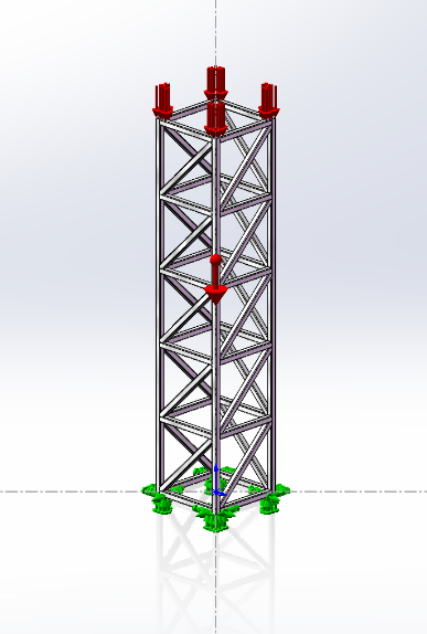
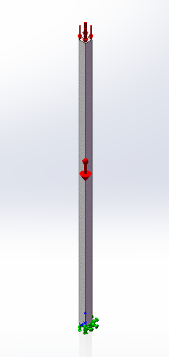
(a) The model of the truss structure. | (b) The model of columnar structure. |
Figure 4. The model of truss support (a) and columnar support (b) with the fixed methods and the loading conditions (Photo/Picture credit: Original). | |
3. Research methods
To study the stress, strain and deformation of truss structure under external force, this study used SolidWorks Simulation to perform finite element analysis. The detailed operation steps were as follows: Draw the truss and columnar structure models in the project file and set the dimensions and boundary conditions. This study made the volumes of the truss structure and columnar structure close, which were 96.897 mm3 and 97.024 mm3, respectively (Due to the presence of welding points in truss structures, there may be small errors in the volume parameters), and their height was 50.8 mm. Then, get the model of 2 structures (Figure 4). Apply the same vertical downward pressure of 1 N/mm2 to the supporting points at the top surfaces of the two structures. Setting the grid accuracy to 0.5 mm and the gravity acceleration to 9.81 N/kg.
Select the material properties for each member of the two structures. This study chose ABS because it was a common engineering plastic in commercial 3D printing. Run the static simulation, observe and record the distribution graphs of stress, deformation and strain of the two structures (Figure 5).
|
|
|
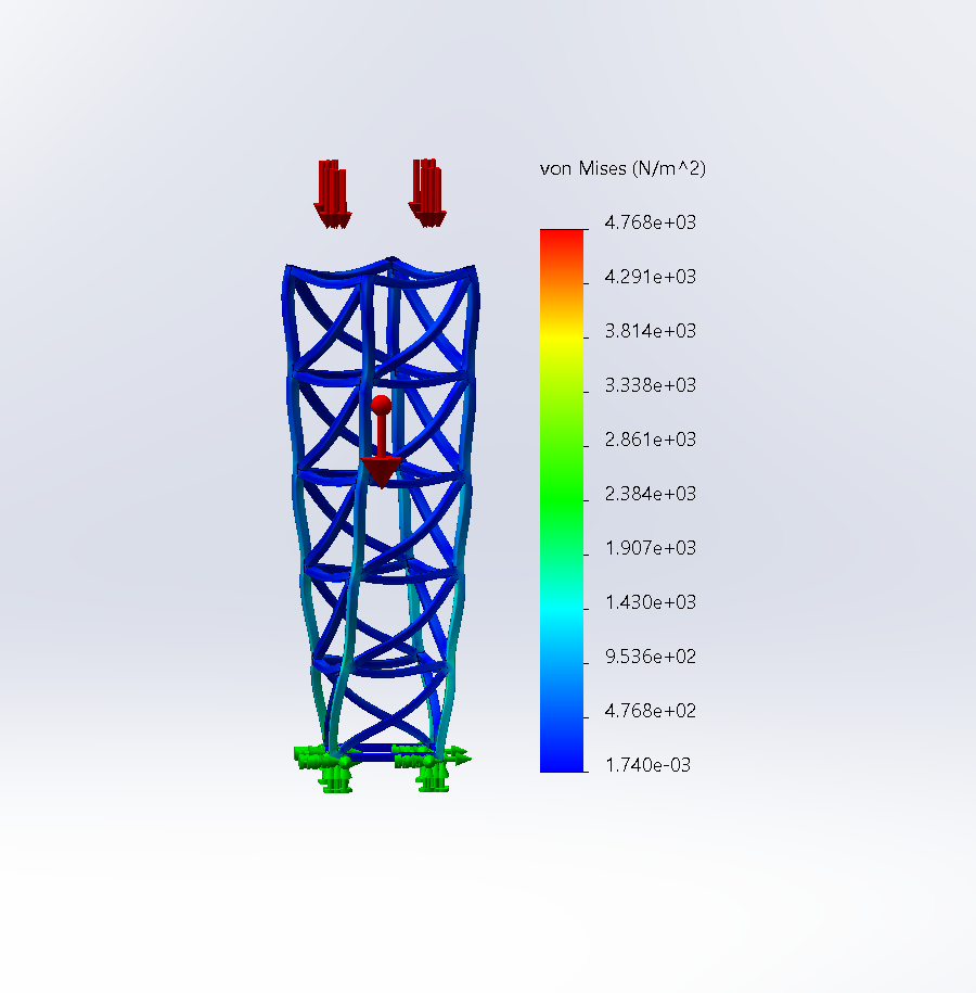
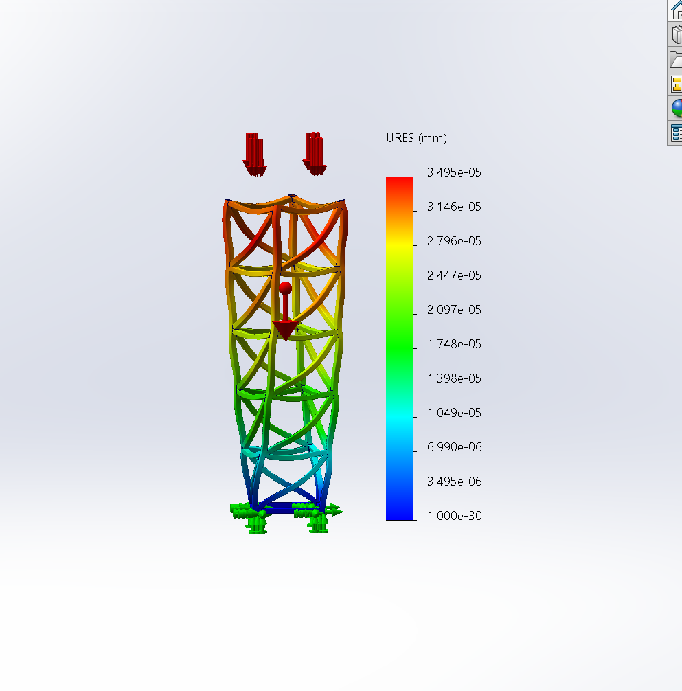
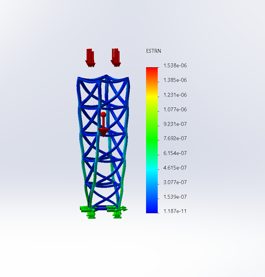
(a) truss-stress. | (b) truss-dislocation. | (c) truss-strain. |
|
|
|
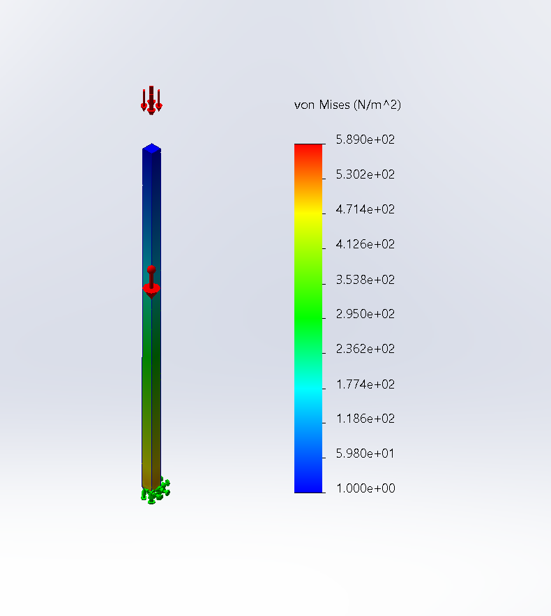
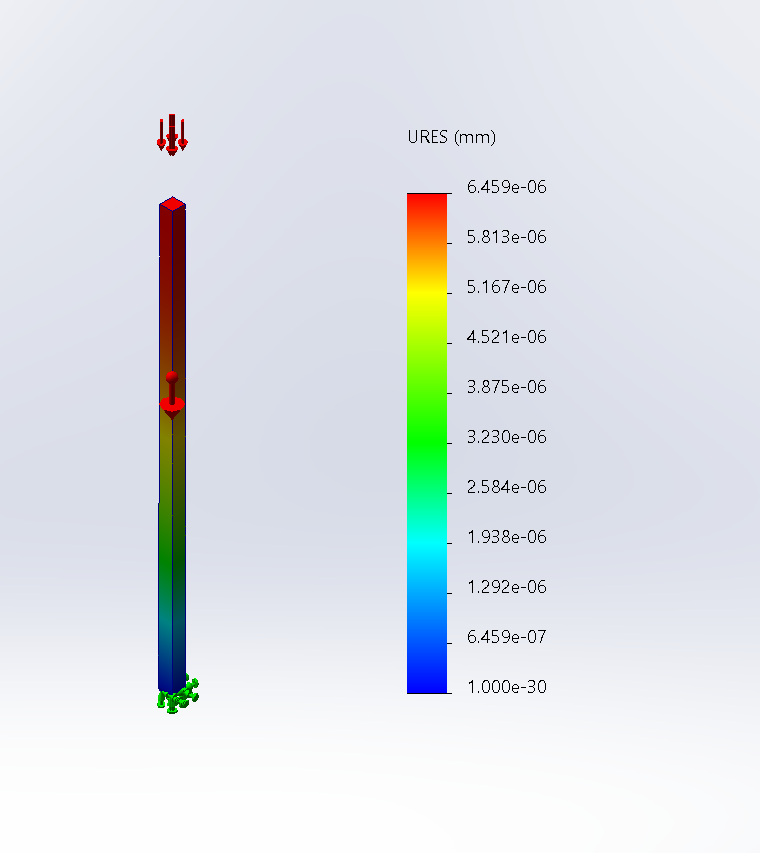
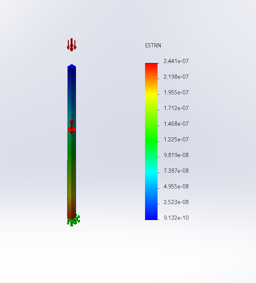
(d) columnar-stress. | (e) columnar-dislocation. | (f) columnar-strain. |
Figure 5. Simulation result graphs for truss structure (a, b, c) and columnar structure (d, e, f) (Photo/Picture credit: Original). | ||
4. Results and discussion
The simulation compares the truss and columnar support structures, focusing on the maximum stress, dislocation and strain when 1 N/m2 pressure was added on the top supporting surfaces. First, define the consumption of the 2 structures. Vtruss = 96.897 mm3 ≈ VColumnar = 97.024 mm3. There are a large number of welding points in truss structures. The volume of the 2 structures can be kept the same in an acceptable range. This step is to control the variables.
Then, for the maximum stress, dislocation and strain. The truss structure exhibited maximum stress of 4.768e+03 Pa, maximum dislocation of 3.495e-05 mm, and maximum equivalent strain of 1.538e-06. On the other hand, the columnar structure had a maximum stress of 5.890e+02 Pa, maximum deformation of 3.459e-06 mm, and maximum equivalent strain of 2.441e-07. These values of the truss structure are an order of magnitude larger than the columnar structure, showing that the truss structure deforms far more and experiences far more intense internal stress distribution when external forces are added.
This result seems strange. The dislocation of the truss structure is more severe than the columnar structure. However, it does not mean the columnar structure is better than the truss structure because its maximum stress and strain values are far higher. On the contrary, it shows that the truss has more possibility to bear more force. The main reason is that the bars in a truss structure primarily bear axial tension or compression, but the bars in a columnar structure must also load shear and bending moments. Thus, the truss structure can spread the forces into various components more uniformly, while the columnar structure cannot. To explain the analysis more precisely and visually, compare the two structures' stress and strain distribution simulation patterns. In the simulation result graphs, it is evident that the truss structure shows a more uniform color distribution of stress and strain, with each bar covering a different color variation relating to the values of the forces it bears. While for the columnar structure, the color of stress and strain distribution is more uneven. Although it produces lower stress, strain, and deformation, it does not imply superiority over a truss structure. In fact, the distribution of stress and strain is more uneven in a columnar structure. The uneven distribution means that certain parts may be unable to withstand the forces, potentially resulting in overloading or failure of some bars. Therefore, this lower stress, strain, and deformation do not indicate increased strength but rather an inadequate utilization of material strength and an uneven concentration of external forces on specific members. Therefore, it can be concluded that the truss support structure has higher material efficiency and lower costs in permitted conditions. It also provides greater stability and safety.
5. Conclusions
In conclusion, this study aimed to compare truss and columnar structures' support performance in 2.5-axis printing, an important topic in additive manufacturing. SolidWorks simulation software was the primary method for conducting finite element analysis on structures under identical volume and external force conditions. The simulation results revealed significant disparities between the truss and columnar structures. Notably, the truss structure demonstrated superior utilization of material strength compared to the columnar structure. This signifies that the truss structure efficiently employed the material, resulting in a higher strength-to-weight ratio. Consequently, the truss structure displayed favorable support performance while minimizing material consumption, which holds notable advantages in cost-effectiveness and resource conservation.
Moreover, the simulation results indicated that the truss structure displayed a more uniform stress and strain distribution than the columnar structure. This uniform distribution suggests that the truss structure effectively redistributes the load, mitigating the likelihood of localized overloading or failure. The enhanced stress and strain distribution bolstered the truss design's overall stability and structural integrity. In sum, this study showcases the truss structure’s potential to fulfill the demands for support strength and printing efficiency in additive manufacturing. The truss structure presents heightened material strength utilization and offers improved stability through an even stress and strain distribution. These findings provide valuable insights for designers and engineers seeking to optimize support structures in additive manufacturing processes. Overall, this research underscores the advantageous support performance of the truss structure, with the added benefits of reduced material consumption.
However, many relative problems still need to be solved: Refinement of the truss support method: Future research can focus on optimizing the design parameters and configurations to achieve even higher support strength and efficiency. Or design an algorithm to automatically generate truss support based on the model. Varied load conditions: This study only considered vertical downward pressure. Future work can investigate truss support performance under different load conditions, such as lateral forces or dynamic loading. This would evaluate the capabilities and limitations of the truss support more precisely. Comparison with other support methods: Compared with current support structures, such as lattice and tree-like structures, it can help select the most proper method for different conditions.
References
[1]. Ngo T, Kashani A, Imbalzano G, Nguyen K and Hui D 2018 Composites Part B-Engineering 143 172
[2]. Li Z, Xu R, Lu W et al. 2021 Machine Tool & Draulics 49 76
[3]. Zhang N, Zhang L, Chen Y, et al. 2019 Computer-Aided Design 115 277
[4]. Wu J, Wang C, Zhang X and Westermann R 2016 Computer-Aided Design 80 32
[5]. Schmidt R and Umetani N 2014 CM Press ACM SIGGRAPH 2014 Studio-Vancouver (2014.08.10-2014.08.14)
[6]. Hu K, Jin S and Wang C 2015 Computer-Aided Design 65 1
[7]. Beer F, Johnston E, Mazurek D, Cornwell P and Self B 2019 Vector Mechanics for Engineers: Statics and Dynamics Twelfth Edition 10121 301
[8]. Mazurek A, Baker W and Tort C 2011 Structural and Multidisciplinary Optimization 43 231
[9]. Jeffrey S, Jessica H, Irving O and Andrew W 2002 ACM Transactions on Graphics 21 295
[10]. Brütting J, Desruelle J, Senatore G and Fivet C 2018 Structures 18 128
[11]. Queheillalt D and Wadley H 2005 Materials Science and Engineering A 397 132
[12]. Wang H and Rosen D 2002 International Design Engineering Technical Conferences and Computer and Information in Engineering Conference 1 759
Cite this article
Lin,S. (2024). Truss support for additive manufacturing. Applied and Computational Engineering,56,120-125.
Data availability
The datasets used and/or analyzed during the current study will be available from the authors upon reasonable request.
Disclaimer/Publisher's Note
The statements, opinions and data contained in all publications are solely those of the individual author(s) and contributor(s) and not of EWA Publishing and/or the editor(s). EWA Publishing and/or the editor(s) disclaim responsibility for any injury to people or property resulting from any ideas, methods, instructions or products referred to in the content.
About volume
Volume title: Proceedings of the 4th International Conference on Materials Chemistry and Environmental Engineering
© 2024 by the author(s). Licensee EWA Publishing, Oxford, UK. This article is an open access article distributed under the terms and
conditions of the Creative Commons Attribution (CC BY) license. Authors who
publish this series agree to the following terms:
1. Authors retain copyright and grant the series right of first publication with the work simultaneously licensed under a Creative Commons
Attribution License that allows others to share the work with an acknowledgment of the work's authorship and initial publication in this
series.
2. Authors are able to enter into separate, additional contractual arrangements for the non-exclusive distribution of the series's published
version of the work (e.g., post it to an institutional repository or publish it in a book), with an acknowledgment of its initial
publication in this series.
3. Authors are permitted and encouraged to post their work online (e.g., in institutional repositories or on their website) prior to and
during the submission process, as it can lead to productive exchanges, as well as earlier and greater citation of published work (See
Open access policy for details).
References
[1]. Ngo T, Kashani A, Imbalzano G, Nguyen K and Hui D 2018 Composites Part B-Engineering 143 172
[2]. Li Z, Xu R, Lu W et al. 2021 Machine Tool & Draulics 49 76
[3]. Zhang N, Zhang L, Chen Y, et al. 2019 Computer-Aided Design 115 277
[4]. Wu J, Wang C, Zhang X and Westermann R 2016 Computer-Aided Design 80 32
[5]. Schmidt R and Umetani N 2014 CM Press ACM SIGGRAPH 2014 Studio-Vancouver (2014.08.10-2014.08.14)
[6]. Hu K, Jin S and Wang C 2015 Computer-Aided Design 65 1
[7]. Beer F, Johnston E, Mazurek D, Cornwell P and Self B 2019 Vector Mechanics for Engineers: Statics and Dynamics Twelfth Edition 10121 301
[8]. Mazurek A, Baker W and Tort C 2011 Structural and Multidisciplinary Optimization 43 231
[9]. Jeffrey S, Jessica H, Irving O and Andrew W 2002 ACM Transactions on Graphics 21 295
[10]. Brütting J, Desruelle J, Senatore G and Fivet C 2018 Structures 18 128
[11]. Queheillalt D and Wadley H 2005 Materials Science and Engineering A 397 132
[12]. Wang H and Rosen D 2002 International Design Engineering Technical Conferences and Computer and Information in Engineering Conference 1 759