


1. Introduction
The Federal Aviation Administration (FAA) guidelines recommend maintaining a specific distance between the centerline of the end-around taxiway and the ends and sides of the runway. The design of the end-around taxiway should consider factors such as the runway end, elevation of the end-around taxiway, and the tail height of the designated aircraft. In some cases, it may be beneficial for the end-around taxiway to have a lower elevation than the runway end. To ensure compliance with safety regulations, a comprehensive net clearance analysis must be conducted during the design phase, ensuring that the tail height of the designated aircraft remains within the required limit. Additionally, it is important to note that the end-around taxiway should be constructed entirely outside of the critical area covered by the Instrument Landing System (ILS) [1].
Since 2009, numerous industry professionals have undertaken research on the design and operation of end-around taxiways. Baiyan Su conducted a study focusing on the concept, significance, and considerations associated with implementing end-around taxiways [2]. Dexiong Jin's ongoing research at Hongqiao Airport addressed bottleneck issues that hindered the use of the end-around system. Jin also developed an operational mode and infrastructure construction plan for the end-around system at Hongqiao Airport [3]. Yawen Zhao discussed the layout and usage strategy of the end-around system at Hongqiao Airport, emphasizing its positive impact on smooth operations, reduced runway crossings, and decreased workload for pilots and controllers [4]. Xuanjin Liao, in conjunction with the end-around construction at Guangzhou Airport, summarized five critical factors that must be taken into account during the construction phase: obstacle clearance, approach light shielding, ILS operation, flight procedures, and aircraft performance [5].
Currently, such as Shanghai Hongqiao airport, Guangzhou Baiyun airport, Chongqing Jiangbei airport, and Guiyang Longdongbao airport have implemented end-around taxiways. Hongqiao's end-around system passed acceptance inspection in 2010 but was not put into operation until October 2021, becoming the first airport to use the runway end end-around system. There is currently a lack of experience in the design and operation of end-around taxiways. High plateau airports face additional challenges, such as a high water table and a low obstacle clearance gradient. This paper introduces the issues and solutions encountered in the plane and vertical design of the end-around system in the second runway project at a specific high plateau airport, providing valuable reference for end-around taxiway design and operation.
2. End-Around Taxiway Plane Planning at a Certain Airport
The airport is situated at approximately 3000 meters elevation. The proposed plan for constructing a second runway includes placing it 380 meters north and 350 meters west of the existing runway. The current airport terminal is located in the T3 area, leaning towards the western end of the runway. Due to construction constraints, building an end-around taxiway east of the runway's end is not feasible. Considering the terminal's position, two sets of end-around taxiways have been designed to the west: one on the near side and one on the far side.
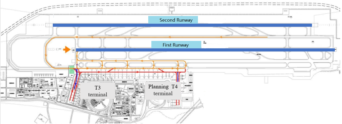
Figure 1. Airport Plan of the High Plateau Airport
The access points for the end-around taxiways are located on the apron taxiway to the south of the first smooth taxiway. The near-side end-around taxiway operates in a west-to-east direction, following an inner departure and outer arrival pattern. It intersects with the departure runway's starting end, but the proximity of the end-around taxiway does not impact departures from the inner runway when aircraft land on the second runway at the west end. To ensure safety, the near-side end-around taxiway is positioned outside the safety zone and approximately 420 meters beyond the short light band at the west end of the existing runway. It is situated roughly 470 meters from the runway's end centerline, adhering to Class E standards.
When considering the far-side end-around taxiway, which operates in a west-to-east direction following an inner departure and outer arrival pattern, it intersects with the departure runway's end. However, it does not affect the navigational lights and communication navigation facilities of the first runway. The main focus is on ensuring that the aircraft's tail does not impact obstacle limitation surfaces. For instance, when accounting for a Class E aircraft like the A330 with a tail height of 18.73 meters, the distance between the west end of the first runway and the far-side end-around taxiway exceeds 1500 meters, resulting in a longer taxiing distance. As a result, the design of the far-side end-around taxiway only considers Class C aircraft, taking into account factors such as the aircraft's tail height, aircraft performance analysis, and groundwater conditions.
3. The elevation and plane scheme of the End-Around Taxiways at a Certain Airport
3.1. Water-Level Conditions
The project is located on the riverbank, with a thick layer of sand and gravel below. The groundwater in the area is well-connected with the river water, making it impractical to lower the groundwater through precipitation or interception. Therefore, special consideration must be given to the groundwater level when determining the elevation for the end-around taxiway. Through specialized studies, the water levels during high-flow periods and once-in-a-century events on the west side of the far-side end-around taxiway are estimated, as shown in Figure 2 and Table 1.
Considering the operational requirements of the end-around taxiway, the principle of setting the elevation without pooling during the high-flow period in the taxiing area is adopted. It is inferred that 3569.2m is the minimum control elevation for the centerline of the taxiway.
Table 1. Statistics of Groundwater Level and Pavement Elevations
Operating Condition | High-Flow Period | Once-in-a-Century Event | |
End-Around Taxiway North Side Elevation (m) | C1 | 3568.72 | 3569.48 |
End-Around Taxiway Central Part Elevation (m) | D1 | 3568.73 | 3569.37 |
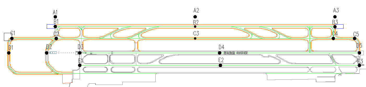
Figure 2. Field Region Water-Level Altitude Spot Location
3.2. Straight End-Around Taxiway Scheme
The end-around taxiway is situated 940 meters west of the runway, and its smooth westward extension enters the obstacle limitation surface at the existing runway's end at a distance of 903 meters. With a one-engine-out obstacle control gradient of 1.2%, the taxiway's elevation is 3567.8 meters, which is 90 centimeters below the normal water level. During the summer, the pavement gets submerged, making it unusable. As a result, this option is not considered. On the other hand, with a one-engine-out obstacle control gradient of 1.35%, the control elevation of the end-around taxiway segment is 3569.2 meters. This elevation provides advantages for drainage and flood prevention, and the taxiway surface area and pavement area are not prone to flooding.
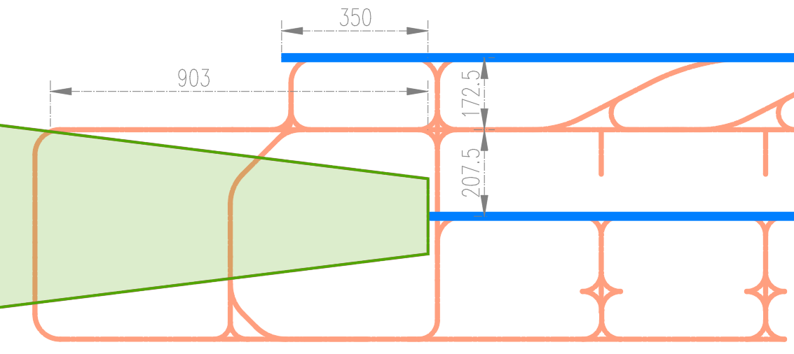
Figure 3. Straight End-Around Taxiway Plan
3.3. Oblique End-Around Taxiway Scheme
The far-side end-around taxiway extends diagonally to the north, bypassing the one-engine-out obstacle limitation surface and intersecting it at a distance of 1010 meters from the existing runway's end. With a one-engine-out obstacle control gradient of 1.2%, the limiting elevation for the end-around taxiway is 3569.15 meters. The surface area is generally higher than the normal water level, which fulfills operational requirements. However, it should be noted that the taxiing distance is approximately 150 meters longer compared to the straight end-around taxiway scheme.
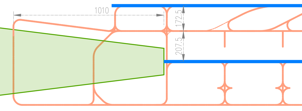
Figure 4. Oblique End-Around Taxiway Plan
3.4. Control Scheme
A straight design is implemented for the end-around taxiway on the airport. Its far end is situated 940m away from the existing runway's end. To accommodate a one-engine-out gradient of 1.35%, the elevation of the taxiway is set at 3569.2m. Operational control measures are in place to restrict the use of the far-end end-around taxiway during A319 take-offs. This precautionary approach prevents challenges associated with high obstacle clearance gradients and potential pavement flooding.
4. Aircraft Performance Analysis Under Different Gradients
The approach and takeoff climb surfaces of the far-side end-around taxiway feature relatively steep gradients. The net clearance constraints primarily focus on the impact of the one-engine-out obstacle limitation surface, as its gradient directly affects the aircraft's payload. Class C aircraft models, such as the A319 and B737-700, are used on the far-side end-around taxiway, while considering A319, B737-700, and A330 for takeoff from the primary runway. The payload analysis for various gradients is presented in Table 2.
Table 2. Aircraft Load Calculation Table
Aircraft Model Gradient | 1% | 1.2% | 1.28% | 1.35% |
A319-133 | 64.5 | 64.3 | 64.3 | 64.3 |
B737-700W | 59.2 | 59.2 | 59.2 | 59.2 |
A330-243 | 172.5 | 172.5 | 172.5 | 172.5 |
Note: Consideration for the summer and autumn flight season, baseline temperature of 25°C, and dry runway.
The analysis presented in the table demonstrates that gradients ranging from 1% to 1.35% on the one-engine-out obstacle limitation surface of the far-side end-around taxiway have no impact on the payload of B737-700W and A330-243 aircraft during takeoff from the primary runway.
Obstacles with gradients equal to or exceeding 1.2% should be marked on the obstacle Type A chart, whereas those below this threshold do not require marking. For A319 aircraft taking off from the primary runway, if obstacles with a 1.2% gradient are marked on the Type A chart and included in the performance calculations, a payload reduction of 0.2t is necessary. However, if these obstacles are not marked, no payload reduction is required. It's only when the limiting gradient drops below 1% that it has no impact on the payload.
The A319 has a tail height of 12.17m, while the B737-700 has a tail height of 12.67m (based on the tail height under the operator's operational empty weight). If we assess the far-side end-around taxiway centerline elevation at a 1% gradient, it would be 3566.43m. However, implementing this gradient would result in the end-around taxiway being submerged for an extended period, rendering it unsuitable. Additionally, constraints from the external flood embankment prevent the extension of the end-around taxiway outward. Therefore, a 1% gradient is not viable.
5. Discussion on the Plane Scheme
After discussions with relevant departments and management units, the control scheme is not being considered. A319 aircraft takeoffs make up approximately 70-80% of the total takeoffs. Restricting the use of the end-around taxiway during A319 takeoffs from the first runway significantly decreases its efficiency, increases control challenges, and raises the risk of encroachment into obstacle limitation surfaces.
Both the straight and oblique end-around taxiway schemes meet the elevation requirements. However, the key consideration lies in whether obstacles with a 1.2% gradient are published and included in performance calculations. After consultation with industry regulatory authorities, it was determined that obstacles with gradients below 1.2% do not necessarily need to be depicted on the Type A chart, but they still have an impact on aircraft performance.
Therefore, they must be clearly marked on the obstacle Type A chart. Given this criterion, both the straight and oblique end-around taxiway schemes have similar effects on aircraft performance. The straight end-around taxiway offers a shorter taxiing distance of 150m, which can also help reduce construction costs. Aircraft performance analysis shows that, following a payload reduction of 0.2t, A319 aircraft can still reach the target city with over 85% passenger capacity during summer and autumn and 100% capacity during winter and spring. Consequently, the impact of the payload reduction is relatively minor. Based on these findings, the straight end-around taxiway scheme is chosen as the final design option.
6. Conclusion
This study, based on a high-plateau airport's second runway project, focused on the design of end-around taxiways. Due to the high local water table, it was not feasible to lower the elevation of the end-around taxiway. Through aircraft performance analysis under payload reduction scenarios, the obstacle limitation gradient for the end-around taxiway was ultimately determined to be 1.35%. The research highlights the importance of considering the impact of tail height on aircraft performance in end-around taxiway design. Taking into account both payload and water level conditions, the planar and vertical design of the end-around taxiway was established. However, this study did not consider the runway operation mode and the impact of the taxiway system. Therefore, comprehensive optimization of the taxiway system design could be achieved through operational simulation analysis in future work.
References
[1]. Federal Aviation Administration (FAA). Advisory Circular (AC) 150/5300-13B Airport Design[S].2022
[2]. Su, B. Y. (2009). Preliminary exploration of taxiway bypass application[J]. Shanghai Airport (Issue 10) (pp. 30-33). Shanghai.
[3]. Jin, D. X. (2017). Application Research of Hongqiao Airport End-Around Taxiway System[J]. Chinese & Overseas Architecture, 2017(09), 161-163.
[4]. Zhao, Y. D. (2022). An analysis of the structure and operations of the end-around taxiways at Hongqiao Airport[J]. Civil Aviation Management, 2022(05), 80-83.
[5]. Liao, X. J. (2018). Research on the construction method of airport taxiway bypass[J]. Low Carbon World, 2018(10), 232-233.
Cite this article
Wu,S. (2024). Plane and vertical design research on end-around taxiways at high plateau airports. Applied and Computational Engineering,63,56-61.
Data availability
The datasets used and/or analyzed during the current study will be available from the authors upon reasonable request.
Disclaimer/Publisher's Note
The statements, opinions and data contained in all publications are solely those of the individual author(s) and contributor(s) and not of EWA Publishing and/or the editor(s). EWA Publishing and/or the editor(s) disclaim responsibility for any injury to people or property resulting from any ideas, methods, instructions or products referred to in the content.
About volume
Volume title: Proceedings of the 4th International Conference on Materials Chemistry and Environmental Engineering
© 2024 by the author(s). Licensee EWA Publishing, Oxford, UK. This article is an open access article distributed under the terms and
conditions of the Creative Commons Attribution (CC BY) license. Authors who
publish this series agree to the following terms:
1. Authors retain copyright and grant the series right of first publication with the work simultaneously licensed under a Creative Commons
Attribution License that allows others to share the work with an acknowledgment of the work's authorship and initial publication in this
series.
2. Authors are able to enter into separate, additional contractual arrangements for the non-exclusive distribution of the series's published
version of the work (e.g., post it to an institutional repository or publish it in a book), with an acknowledgment of its initial
publication in this series.
3. Authors are permitted and encouraged to post their work online (e.g., in institutional repositories or on their website) prior to and
during the submission process, as it can lead to productive exchanges, as well as earlier and greater citation of published work (See
Open access policy for details).
References
[1]. Federal Aviation Administration (FAA). Advisory Circular (AC) 150/5300-13B Airport Design[S].2022
[2]. Su, B. Y. (2009). Preliminary exploration of taxiway bypass application[J]. Shanghai Airport (Issue 10) (pp. 30-33). Shanghai.
[3]. Jin, D. X. (2017). Application Research of Hongqiao Airport End-Around Taxiway System[J]. Chinese & Overseas Architecture, 2017(09), 161-163.
[4]. Zhao, Y. D. (2022). An analysis of the structure and operations of the end-around taxiways at Hongqiao Airport[J]. Civil Aviation Management, 2022(05), 80-83.
[5]. Liao, X. J. (2018). Research on the construction method of airport taxiway bypass[J]. Low Carbon World, 2018(10), 232-233.