


1. Introduction
The primary motivation for researching advanced joinery in vehicle building is to increase structural integrity and safety, as it immediately adds to the capacity to reduce vehicle weight, which is the simplest technique to improve fuel efficiency. Lightweight materials like aluminum and composites are increasingly becoming suitable for improving fuel efficiency. The different materials are difficult for manufacturers to connect. Because of the differences in material properties, modern procedures offer alternatives for bonding dissimilar materials, allowing manufacturers to achieve their lightweight goals.
While most existing research focuses on a single type of connection method, it is important to explore the various connection methods that can be applied to cars and their specific locations. The suitability of these connection methods can be determined by analyzing factors such as yield strength, bending strength, and fatigue performance. To investigate the performance of these connection joints, this paper collects five kinds of connection ways’ detail parameters.
To solve the problem of connecting different materials to reduce the weight of vehicles, a lot of previous research was developed. Researchers have devoted efforts to researching the properties and improving the joinery methods. This article will discuss five different joinery methods. Ultrasonic welding is often used as a new solid-state welding technique. Zhao et al. [1] established a model to analyze the properties of ultrasonic welding of magnesium and copper. They found that the model could match the temperature result gained from the experiment.
Besides wielding, other joinery methods were studied previously. First, clinching is often used to connect lightweight constructions. B. Schramm et al. set experiments and analysis to answer the questions “Which process parameters are significant for the joining process, and how do they affect the resulting properties of the clinched joint?” and “What is the role and influence of damage during the clinching process and how can it be modeled and simulated?” However, the material description and the experimental test setups will be further developed for different materials [2]. Second, bolting is one of the most common joinery methods. It was invented by Archytas in Ancient Greece, but the use of metal screws as fasteners began in Europe in the 15th century [3]. Due to its convenience, it can be used to connect different materials, regardless of differences in different materials, for a lightweight vehicle. Y. Zheng et al. tested bolt connections to connect carbon fiber reinforced polymer (CFRP) laminate and titanium alloy plates. They found optimized ways to reinforce the strength and safety of the connection [4]. Third, riveting Interface-fit riveting is one of the most widely used mechanical joining methods in aircraft assembly. J. Liu et al. studied the stress distribution model of the riveted lap joint concerning rivet load and bypass load. They improved the design and structure of riveting [5].
This paper will reference current research study papers to find the advantages of different joinery methods, such as ultrasonic welding, bolts and nuts, riveting, and clinching. These methods will be compared using three mechanical properties: yield strength, fatigue, and bending of the joints. In this paper, these mechanical properties of joints will be investigated using references from current research study papers. In each section, three properties of joints are discussed.
2. Discussion
2.1. Clinching

Figure 1. Steps of the clinching process and important geometric parameters of the clinched joint [6].
Clinching, also known as press joining, is a high-speed, mechanical fastening technique for point-joining sheet metal components, as shown in Fig. 1 [6]. With the development of vehicle manufacturing, advanced lightweight (e.g., carbon fiber and aluminum alloys) materials are used to reduce the weight of cars. However, the connection between different materials becomes a new issue in the manufacturing process; for example, aluminum alloys, which are used in many fields (chemical, aviation, aerospace, automobile, etc. [7]), are difficult to be connected through conventional spot welding. Therefore, mechanical joinery has developed, and clinching is a good substitute for spot welding. The performance of clinched joints is determined by the geometry of the joints, which is affected by the combination of process parameters and mold parameters [8,9]. However, clinching joints can be divided into different forms, for example, overlap clinching, single-point butt clinching [8], HSMC [10], etc.
2.1.1. Yield strength
Many researchers investigated the effect of process parameters, performed the shape of lower sheets, geometrical parameters of dies, and so on [7]. Well, few people focus on different materials. In the paper of Zhang et al. [7], They managed to investigate the forming properties of cinched joints of four distinctive aluminum sheets (1060, 5754, 6061, and 7075, whose mechanical properties are shown in Table 1. [7]). The specification of sheets is the same when changing punch and dies, clinching by lap joints, and cross joints.
Table 1. Mechanical properties of four materials [7]
Material | Tensile strength (MPa) | Yield strength (MPa) | Shearing strength (MPa) | Young’s modulus (GPa) |
Al7075 | 572 | 503 | 331 | 72 |
Al1060 | 110~136 | 90 | 75.8 | 68.9 |
Al6061 | 310 | 276 | 205 | 68.9 |
Al5754 | 165~256 | 179 | 285 | 69.3~70.7 |
In the tensile-shear test, the average failure loads are 2507N, 2495N, 2361N, and 1450N separately for lap joints [7], shown in Fig 2. which shows that the average failure load increases with the rise of material properties such as yield strength. Regarding cross joints, the average failure loads are 1926N, 1974N, 1851N, and 938N, respectively, which are generally lighter than lap joints. In the peeling test, 1060 aluminum alloy shows less load capacity and less maximum failure displacement than the other three materials, probably due to its lower yield strength [7]. Overall, because of its low yield strength, the joint of 1060 alloy shows weaker tensile yield strength. However, the energy absorption data of 1060 is better than its load capacity due to its plasticity. In terms of failure modes of these sheets, it is mainly decided by the different material’s properties, yield strength, tensile strength, etc [7].
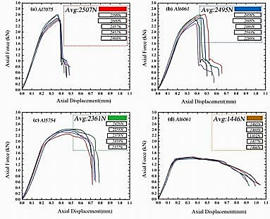
Figure 2. Load– Load-displacement curves of the lap joints of different aluminum alloys [7].
2.1.2. Bending
Clinching, as an alternative joining method of spot welding, enables multi-material sheets to be connected, which welding cannot achieve because of different formability, melting points, etc., such factors even though the strength of clinched joints is weaker than that of welded joints. In previous studies, yield strength, shear strength, and so on have been investigated [7,10] while bending behavior is also a crucial aspect that needs to be investigated since it is also a typical load exerted on components, for example, side door impact beam, bumper beam, B-pillar, etc. In Khalkhali and Miandoabchi’s paper [11], they manage to investigate the aspect of bending. The specifications of the clinching tools used in the experiments are shown in Table 1. Aluminum alloy Al 5052 H-14 and high-strength steel SPFC 390 are utilized in the experiments. Sheets are clinched following the specimen of the top-hat template, shown in Fig. 3 [11], and clinched sheets will be tested by a three-point bending test.
Table 2. Specifications of the clinching press [11].
Cylinder Bore | \( ∅ 50 mm \) |
Hydraulic Pressure | \( Max 2500 psi/172 bar \) |
Force Output | \( 0-3.3 ton/0-33 KN \) |
Max. Stroke | \( 120 mm \) |
Height C-Form (Y) | \( 180 mm \) |
Throat Depth | \( 330 mm \) |
Min Metal Thickness (CRC) | \( (2x) 0.008”/0.2 mm \) |
Max Metal Thickness (CRC) | \( (2x) 0.08”/2 mm \) |
Power Requirement | \( 220 or 380 V \) |
Recommended Oil | \( Hydraulic Oil 68 \) |
Dimension Unit | \( 400*500*600 mm \) |
Power Consumption | \( 5.5 hp \) |
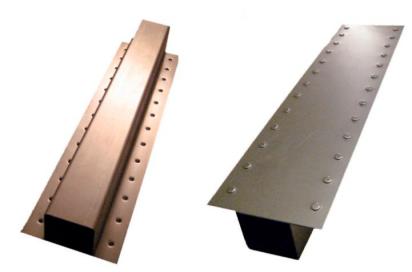
Figure 3. Two views of top-hat clinched sheets [11].
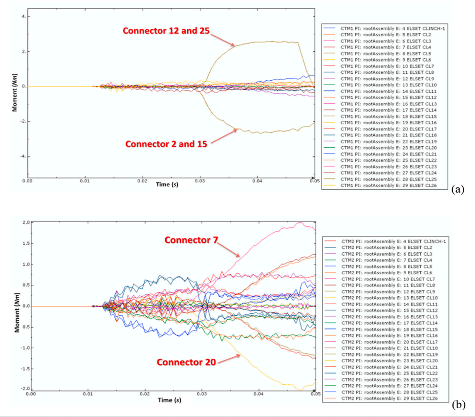
Figure 4. Connecting moments of value m1(a), and m2(b)[11].
Before Khalkhali and Miandoabchi’s experiment [11], a numerical simulation of the points bending test was done by using the FE model, the results of which appear to be close to the results of the experiments. In Fig 4 and 5 [11], bending moments and force applied to connectors are shown. To be short, the maximum forces in the x, y, and z directions are 360N, 470N, and 50N, respectively [11] from Fig.5. It is noticeable that in the z-direction, the force is much lower than x and y directions which probably means the corresponding normal force is relatively higher than others. Moreover, it is easy to know that the connector’s shear force levels are higher by comparing them to their normal forces. However, as mentioned, results from numerical simulations are validated through experiments, which means numerical simulation can be considered an efficient way to predict the mechanical properties of joints, especially bending behavior.
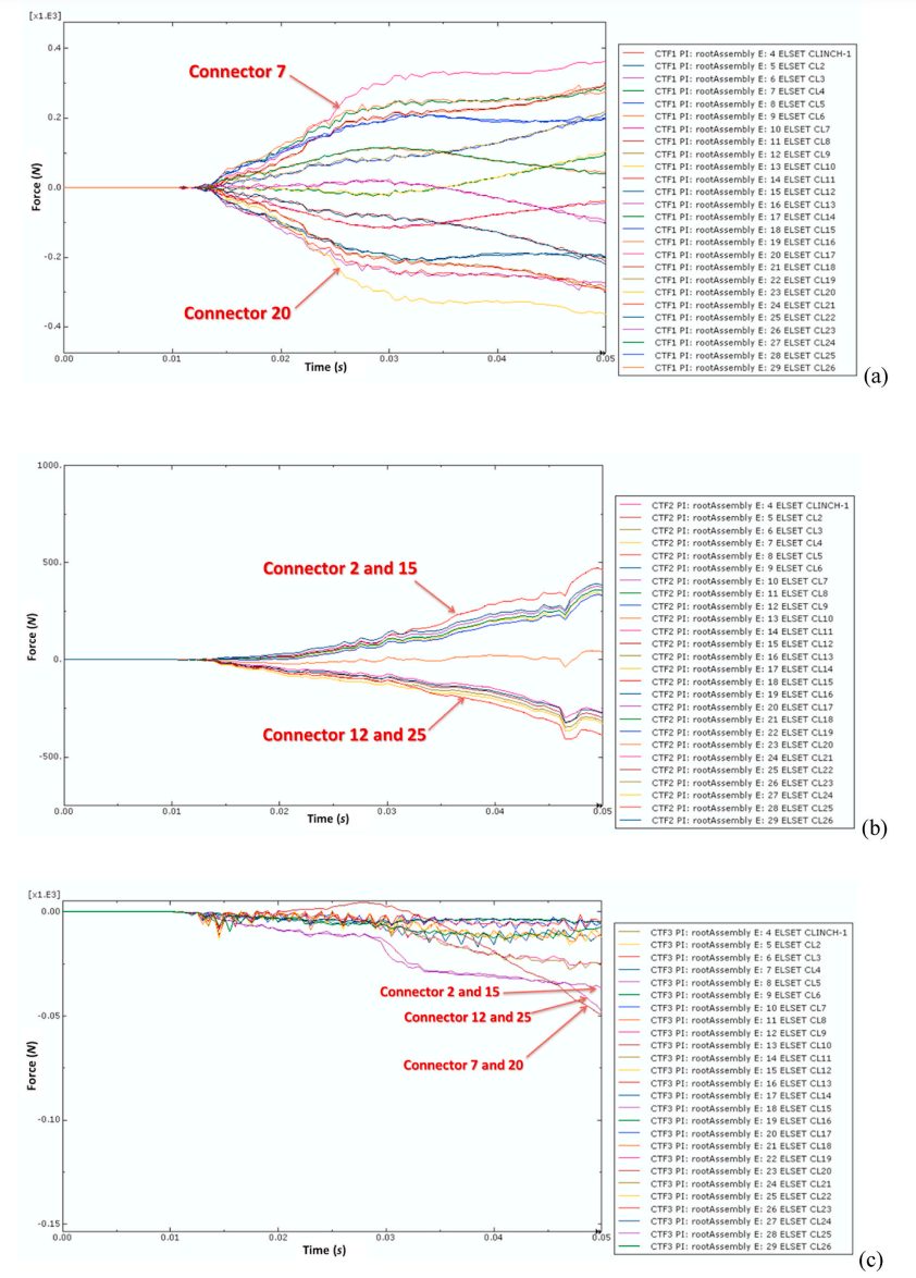
Figure 5. forces history, shear force in the x-axis(a), shear force in the y-axis(c), and total normal force in the z-axis(b)[11].
2.1.3. Fatigue
In previous discussions, yield strength and bending behavior were discussed. However, fatigue of joints is an essential topic. Fatigue failure differs from failure caused by static load. Before the failure, there is no obvious plastic deformation of the joints, which may lead to dangerous sequences because of its suddenness, according to the paper written by Harzheim et al. [12]. Corrosion is the variable to be investigated, which influences the fatigue behavior of clinched joints, as proved by their experiments. A 1mm thick aluminum sheet (EN AW-6014) is clinched to a 1.5 mm thick galvanized steel sheet (HCT590X+Z). A salt spray test is used to corrode the clinched joints, and 0.1 molar NaCl solution is used to set up a three-electrode electrochemical cell. As most researchers do, numerical simulations and experiments are conducted to investigate the relationship between corrosion and fatigue behavior of clinched joints.
In terms of results, the F-N curve of both specimens is shown in Fig.6. It is obvious that pre-corroded joints show better fatigue behavior than that of non-corroded. In Table. 2, the results analyzed by EDS are listed.
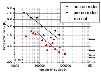
Figure 6. The F-N curve of pre- and non-corroded specimens [12].
Table 3. Exemplary EDS spectra in atomic percentage of a corroded and fatigued specimen [12].
Spectra | O | Na | Al | Cl | Fe | Zn |
1 | 3.5 | - | 96.1 | 0.3 | - | - |
2 | 29.8 | - | 56.3 | 5.0 | - | 8.9 |
3 | 49.0 | 5.0 | 3.8 | 11.7 | 1.3 | 29.2 |
4 | 49.5 | 2.6 | 19.2 | 15.8 | - | 13.0 |
5 | 47.3 | 7.0 | 0.8 | 10.0 | 3.0 | 32.8 |
2.2. Ultrasonic Welding
Ultrasonic welding is a manufacturing procedure that simulates the effects of friction between two pressure-applied surfaces using ultrasonic vibrations. The described motion induces deformation, shearing, and flattening of neighboring surfaces, leading to the dispersal of interfacial oxides and impurities. This process facilitates the establishment of metal-to-metal contact and bonding. In the automotive industry, this technique is commonly used to join plastic components such as interior moldings, lighting fixtures, sensors, and electrical connectors. Welding incompatible lightweight alloys is a crucial step in constructing compel structures. The operation is performed solidly, eliminating the need to liquefy the underlying metal substrate. Utilizing ultrasonic metal welding technology has numerous benefits, including its high speed, automation options, and low cost. This method permits the combination of amorphous, semi-crystalline, and thermoplastic composites, which is shown in Fig.6. By utilizing malleable fixtures and interchangeable horns, ultrasonic welding can also be effectively utilized in low-volume production settings [13].
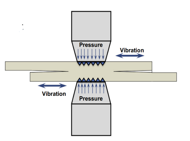
Figure 7. The process of ultrasonic welding [14].
2.2.1. Bending
In ultrasonic welding, bending refers to the unintended deformation or curvature of materials during the joining process. The study involves the utilization of a hollow sphere, steel conduit, fixed endplate, and trough plate to undertake experiments aimed at investigating the arrangement of points for detecting bending in ultrasonic welding. The experimental principle involves joining two hemispheres via ultrasonic welding, as shown in Fig.7 [15]. The result is obtained by rotating the samples through the instrument and measuring the pressure change. This experiment examines the welding residual stress and deformation resistance of welded hollow spherical joints using five groups of spherical joints, as shown in Fig.8. [15] When ultrasonic impact decreases residual pressure, new plastic deforms around the weld, resulting in a decrease in joint force. The ultrasonic impact can significantly reduce the welding residual tension of welded hollow spherical junctions. The geometry of the material is altered by the bending caused by residual tension.
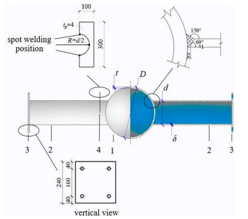
Figure 8. Diagrammatic representation of joint specimen structure [ 15].
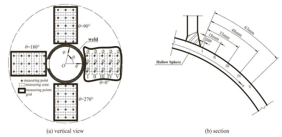
Figure 9. Residual stress measurement point layout [15].
As shown in Fig.9 [15], each group of animals has bending moment-rotation curves that vary similarly. When the load is small, the bending moment-rotation curve gets close to a straight line. This means that the joint is in its elastic stage. As load and angular motion go up, the slope of the curve goes down in a way that is not linear. The hollow spherical joint’s bending moment-rotation graph shows no clear yield platform. In general, welding residual stress has a clear effect on the mechanical properties of joints. For example, cutting welding residual stress at welded hollow spherical joints can improve bending stiffness by up to about 10%. Even though it doesn’t change how much the metal can move in the end.
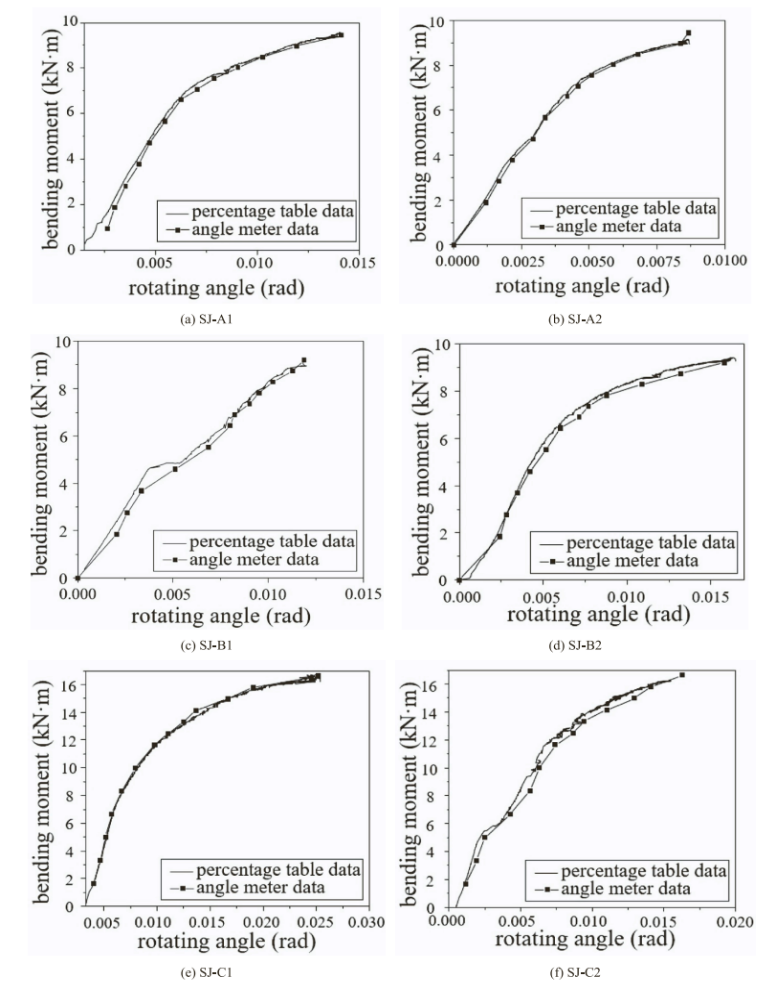
Figure 10. Each test joint’s bending moment-rotation curve [15].
2.2.2. Yield Strength
The relationship between yield strength and ultrasonic welding depends primarily on the quality and strength of the weld joint. The tensile yield strength of a material is the maximum tension it can withstand before deforming plastically. Researchers employed the variable control method to ameliorate fluctuations in welding time, output strength, and strength. Initial tests indicate that welding a corner for longer than 5 seconds reduces its lifespan due to excess, and the optimal width is less than 100 percent. Compression can be performed at pressures ranging from 6.3 bar to 0.5 bar. The displacement-load curve categorizes the strength measurement test data. While ultrasonic welding four sheets, three interfaces are formed, as shown in Fig. 10 [16]. Weld zone 1 is formed by the fusion of aluminum (A1) and copper (C1), weld zone 2 is created by the connecting of copper (C1) and aluminum (A2), and weld zone 3 is produced through the combination of aluminum (A2) and copper (C2). The fracture strength of weld zone 1 is like that of aluminum; weld zones 2 and 3 exhibit less than half the strength of weld zone 1. [16].
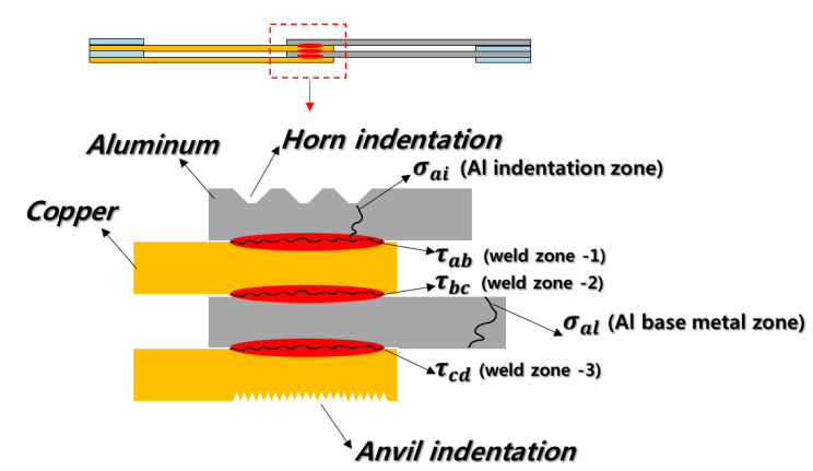
Figure 11. Al and Cu ultrasonically welded in three zones of dissimilar multilayer materials [16].
2.2.3. Fatigue
Ultrasonic welding can influence the fatigue performance of components subjected to residual stresses. The researchers designed the experiment to quantify residual tension. Using SEM methods, the impact load of the spherical indenter is used to generate a new stress field on the original residual stress field of the specimen, with the strain gauge documenting the strain increment value generated throughout the process. The initial residual stress is then estimated using Hooke’s law formula, which is \( 6x = 1 2 (x + vεy) \) , \( 6y = 1 2 (εy + vεx) \) . [17], for the formula, E is the elastic modulus, 210 GPa, and μ is Poisson’s ratio,0.3 and the residual strain is calculated using the relationship between elastic strain and elastic strain increment. Under each fatigue load, four groups of specimens were evaluated, and two separate repeatability investigations were performed.
Maximum stress influences the fatigue life of cruciform-welded joints. As the test’s maximum stress increased, the fatigue life decreased substantially. Ultrasonic treatment should be performed as the final processing step following the cutting operation to increase the fatigue life of the welded structure. Furthermore, high-frequency mechanical vibrations during ultrasonic welding can create microstructural changes that reduce the material’s fatigue resistance, resulting in the initiation of the fatigue fracture. The shape and design of the joint can have a considerable impact on ultrasonic welding performance [18].
2.3. Bolting
Bolting is one of the most common joinery methods. There are many kinds of bolts, including anchor bolts, arbor bolts, and carriage bolts. Most have similar features with bolt heads, thread, and a matching nut. In order to use a bolt, a hole with the same radius as the bolt needs to be made on the materials that are going to be connected. Then, the bolt will be put into it and reach the nut at the other side of the materials. By rotating the bolt, the nut will move along the thread, and finally, the bolt and the nut will create a normal force on the materials to make it be fixed together.
Figure 12. Joint Nomenclature [19].
2.3.1. Yield Strength
Bolts can help two materials achieve a good yield strength under great pressure to make the vehicle safe enough. L. Liu et al. [20] experimented to test the yield strength and tensile strength of different bolts and flanges. Finite Element analysis was also used to develop an estimated model of it. L. Liu et al. used the flange thickness, flange width, flange curvature, bolt layout, and bolt diameter as parameters and conducted an ABAQUS/Standard module. Z. Y. Wang et al. [21] tested three kinds of bolt systems and their yield strength; they conducted experiments and used Finite Element Analysis to test the bolt systems. Eleven test specimens were in the tests, and bolt gauge width, the tube wall thickness, and the bolt shank diameter of the blind bolt were determined as parameters. Finite Element Analysis, using the software ANSYS Academic Research, was used to expand the experiments.
L. Liu’s [20] experiment data is shown in Fig. 2.[20] and Fig. 3.[20] below. The result shows that in order to increase the yield strength of bolt connection, the middle distance of bolts should be reduced, and the edge distance should be increased. Also, the bolt gauge distance should be limited. Z. Y. Wang’s [21] experiment and Finite Element analysis data are shown in Fig. 4.[21] and Table 1.[21], which also shows a comparison of the experimented data and theoretical prediction. They found that bolt gauge width-to-tube width ratio and tube wall thickness-to-half wall width ratio affect the yield strength of bolts the most. These models and experiments are all useful for designing bolts, which can help enhance the yield strength of vehicles. Moreover, the way L. Liu et al. and Z. Y. Wang et al. developed to increase the yield strength of bolts. In this way, the safety of bolt connections and vehicles can be improved.
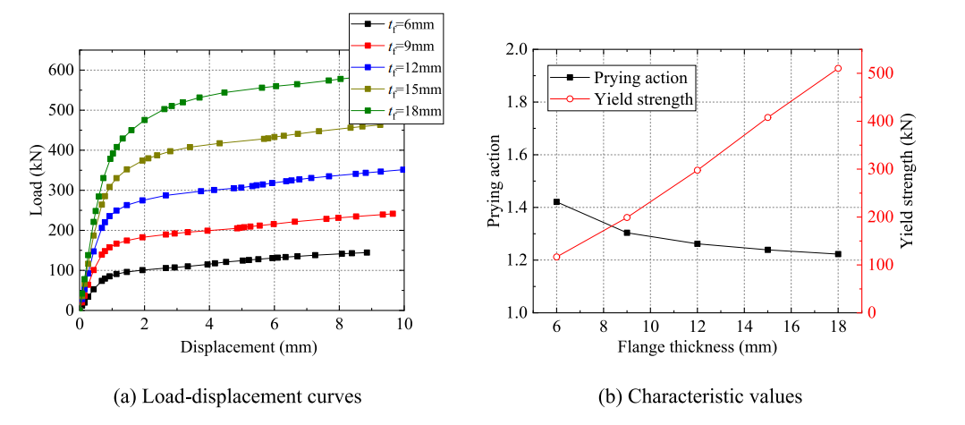
Figure 13. Effects of flange thickness [20].
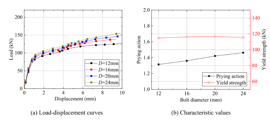
Figure 14. Effects of bolt diameter [20].
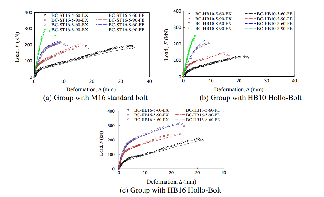
Figure 15. Comparison of Load (F)–deformation (D) relations obtained by experiment and finite element analysis [21].
2.3.2. Bending
Bending load will affect the life of connections, so diminishing the bending load for a bolt connection in order to enhance the safety and the life of the bolt is necessary for bolt connecting. I. O et al. used numerical analysis, experiments, and Finite Element analysis by ABAQUS 2019 software to determine the relationship between additional load, especially bending stress, and dynamic loading of the bolt and its fatigue life. In the experiment, a hybrid bonded butt joint, comprised of a double lap steel-GFRP part and a GFRP sandwich composite part, was used as a specimen. They changed the geometry of the hybrid joint without and with the reinforcing bolt. [22] W. Xu et al. used Finite Element analysis to study the bolted CFRP/aluminum assembled wheel and compared it with a spoke connection under bending conditions. Structure, lay-up, and connection parameters are conducted. They fabricated an assembled wheel to test their optimized design. [23].
I. O’s Finite Element analysis data is shown in Fig. 5.[22]. They found that the additional bending-to-tensile stress ratio can be as high as 6 for lower working loads and about 1 for very high working loads. The stress range and the risk of fatigue damage to the bolt are significantly reduced by using a high washer under the nut. In this way, the fatigue life of the bolt is increased by 300%-500%. [22] L. Liu’s experiment data is shown in Fig. 6.[23]. Their result shows that the bolt connection has a greater fatigue strength and longer fatigue life than the spoke connection under bending conditions. Also, their optimized model was tested and proved to satisfy the standard requirement under bending conditions. [23] By using the way developed by I. O et al. and L. Liu et al., the effect caused by the bending load of bolt connection and vehicles can be diminished, then enhanced fatigue life and safety of the vehicles.
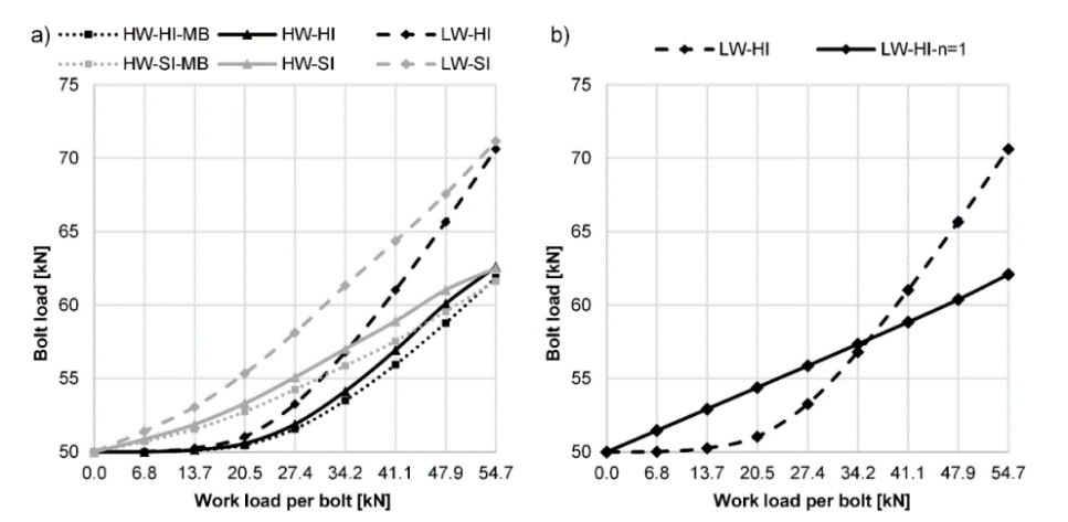
Figure 16. Results of the FE analyses: (a) bending to axial tension stress ratio in the bolt; (b) axial stress in the bolt at various positions [22].
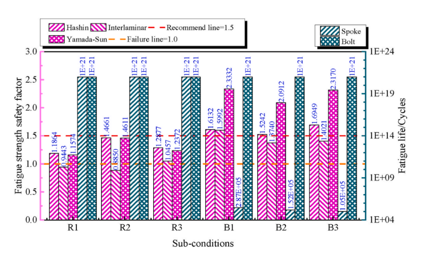
Figure 17. Simulation results of bending and radial fatigue [23].
2.3.3. Fatigue
Working load is unavoidable for connections and will affect the fatigue life of the connection. It is important to find ways to diminish the influence of working load on fatigue of connection to ensure safety. Z. Kapidžić et al. [24] present an analytical model for calculation of the bolt bending moment and the stress and construct experiments to test the fatigue life of the bolt connecting. They used Finite Element Analysis and constructed experiments to test the fatigue life of the bolt connecting. N. A. Noda et al. [25] studied the effect of a slight pitch difference between a bolt and a nut. Finite Element analysis was used in their study, using FEM code MSC.Marc/Mentat 2012. They constructed experiments to test various stress amplitudes under three different pitch values.
Z. Kapidžić’s [24] experimental data is shown in Fig. 7.[24]. They found that the load transfer by friction between the plates is low while the applied force is mainly transmitted through the bolts, which in turn increases the bolt bending stress and reduces the fatigue life. Also, decreasing flexibility is due to increasing load transferred by friction between the plates, which leads to a decrease in bolt bending stress and an increase in the fatigue life of the bolts. N. A. Noda’s experimental data is shown in Table 2 [25]. Bolts can undergo loading tests about 30000 times. It can be concluded that a suitable pitch difference improves both anti-loosening and fatigue life [25]. This shows that bolt connections have a great fatigue life to ensure the safety of vehicles. Moreover, the ways developed by Z. Kapidžić et al. can be applied in vehicle joinery design to improve the fatigue of bolt joinery.
Table 5. Anti-loosening performance [25]
Pitch Differences α | Sample | Nut Drop | Cycles for dropping | Cycles for start loosening | Prevailing torque (N-m) | Axial force2 (kN) |
0 | No.1 | Yes | 751 | - | 0 | 24 |
No.2 | Yes | 876 | - | 0 | 24 | |
No.3 | Yes | 813 | - | 0 | 24 | |
No.4 | Yes | 1528 | - | 0 | 24 | |
No.5 | No | 30000 | 21000 | 30 | 20 | |
No.6 | No | 30000 | 30000 | 30 | 20 | |
No.7 | No | 30000 | 30000 | 67 | 8 | |
No.8 | No | 30000 | 30000 | 57 | 8 | |
No.9 | - | - | - | >70 | - |
Figure 18. Number of cycles to failure [24].
2.4. Rivet
A rivet is a permanent mechanical fastener. Rivets have many applications, such as construction, automobiles, etc. A cylindrical shaft, smooth, with a head at one end is the base before the rivet is installed. For mounting, riveting. When the rivet is inserted into a hole or drill hole, the rivet is firmly held in place by the tail, which is turned over or bent to expand to about 1.5 times the original diameter. Figure 19. explains how rivet operates [26].
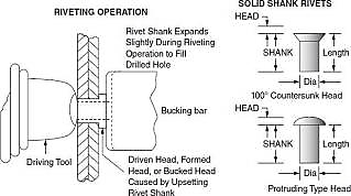
Figure 19. Rivet nomenclature and basic operation.
2.4.1. Yield Strength
In order to balance the strength and weight of self-piercing rivets (SPR), this paper collects the research results on SPR materials suitable for different parts of the automobile. Steel rivets typically have higher strength than aluminum rivets, but steel weighs about three times as much as aluminum. In addition, the connection between aluminum body panels and steel rivets can cause corrosion. Because different applications have different requirements, determining which type of fastener to choose needs to be discussed. Mucha et al. evaluated the mechanical properties of fasteners, including tensile, shear, and impact tests, to assess the strength and stiffness of self-piercing riveted joints. In addition, fixed connection parameters such as pressure and time also affect the strength and shape of the fixed connection points.
Mucha et al. indicate that reducing the thickness of the top material and increasing the strength of the bottom material would result in a higher occurrence and larger size of cracks on the joint button. Different joint types will have different strength [27]. In shear testing, the rivet joint’s strength is influenced by the mechanical properties of the rivet material, such as its shear strength [28]. In tensile testing, factors like rivet diameter, spacing, plate thickness, and width, as well as material properties, affect the strength of the rivet joint [28]. Insufficient riveting time may lead to a weak connection, while excessive riveting time can cause rivet overheating or deformation of materials. Similarly, inadequate force may result in a weak connection, whereas excessive force can lead to material damage or deformation. The strength of the riveted joint based on the upper plate was significantly greater than that based on the bottom plate [29].
2.4.2. Bending Strength
Testing the bending strength of the rivet to prove whether the rivets can protect people from accidents. The bending strength of the rivet can be determined by calculating the bending moment and section modulus of the rivet. The equivalent spring stiffness of the rivet in equation can be inferred by Formula:
\( \frac{1}{KB}=(\frac{2({t_{1}}+{t_{2}})}{{t_{1}}×{t_{2}}×{E_{r}}}+\frac{{t_{1}}+{t_{2}}}{{t_{1}}×{t_{2}}×{E_{b}}})×(1+3β) \) ,
where Ab represents the cross-sectional area of the rivet, Eb represents the shear modulus of rivet and Er is the elastic modulus of the rivet. β is the coefficient to describe the secondary bending, which can be seen as zero due to the bending in the axial direction, which is ignored in this paper. The bending strength of the rivet is determined by many factors, such as diameter and spacing [30]; strength and hardness of the material [31]; and modulus of section [30]. So different rivet will have different bending strength. The finite element models of riveted lap joints with various rivet diameters and pitches are established.
The maximum residual compressive stress of both rivets, 4mm and 5mm rivets, is visible at the pit wall, and the residual compressive stress of rivets is 4mm, 3.74 times that of rivets 5mm [30]. Residual stress can indirectly indicate the bending strength of riveted parts. The larger the diameter of the rivet, the larger and wider the slate produced the stress field. The load on each rivet differs because the distance from where the load is applied differs. By increasing the diameter of the furthest rivet from the drag load, stress concentration can reduce the rivet closest to the pull load, which optimizes the stress distribution of the rivet lap. High-carbon steel rivets have the best bending strength [32].
2.4.3. Fatigue
In order to ensure the safety of the car, it is necessary to determine how to minimize the fatigue of the rivets and ensure the strength of the car. The diameter, spacing, load, and stress distribution of the rivet are all factors that cause rivet fatigue in construction [30]. Fatigue tests, stress distribution analyses, and numerical simulations can be used to evaluate rivet fatigue. In order to reliably predict the fatigue life and take into account the effects of load stress, bypass stress, and interference stress on rivets, Liu et al. developed a prediction model. Liu et al. used a finite element model, along with variables such as distance from applied tensile load and rivet diameter. Finally, the data collected in the experiment are analyzed [30].
The local energy density within 0.4 mm radial thickness of the hole wall of the lower plate is the key area that affects the fatigue life of the riveted structure [8]. The increase of extrusion pressure and initial fitting tolerance will lead to an increase in residual stress. The final compressive stress of 5mm rivets is greater than that of 4mm rivets, as shown in Table 6 [5]. Therefore, the larger the diameter of the rivet, the wider the range of compressive stress; that is, the wider the diameter, the more conducive it is to improve the fatigue performance of the riveted lap. With the increase of the pitch of the rivet, the load is gradually transferred to the rivet with a larger diameter, and the 5-4-4-4 rivet combination has better durability [30].
Table 6. The ratio of rivet loads to tensile load of different group of riveted lap joints.
Group | #4 Rivet | #3 Rivet | #2 Rivet | # 1 Rivet |
4 4 4 4 16 _ _ _ _ | 25.20% | 24.51% | 23.56% | 26.73% |
5 4 4 4 16 _ _ _ _ | 23.335 | 21.90% | 21.08% | 33.69% |
5 4 4 4 18 _ _ _ _ | 22. 15% | 21.39% | 20.86% | 35.61% |
5 4 4 4 20 _ _ _ _ | 20.66% | 21.63% | 20.94% | 36.77% |
4 4 4 5 16 _ _ _ _ | 31.33% | 21.84% | 22.00% | 24.83% |
4 4 4 5 18 _ _ _ _ | 33.68% | 21.75% | 21.71% | 22.86% |
4 4 4 5 20 _ _ _ _ | 34.23% | 21.89% | 21.93% | 21.96% |
5 4 4 5 16 _ _ _ _ | 31.55% | 16.42% | 18. 10% | 33.93% |
5 4 4 5 18 _ _ _ _ | 30.27% | 16.58% | 17.57% | 35.57% |
4 4 4 4 16 _ _ _ _ | 28.59% | 17.08% | 18.01% | 36.32% |
3. Conclusion
Fuel economy can be improved by reducing the weight of vehicles with different materials. As a result of new materials, advanced joinery for different materials should be applied for connections. This paper reviewed and compared the different properties of different advanced joinery, including clinching, ultrasonic welding, bolting, and rivet. Yield strength, bending, and fatigue life were tested for each joinery since these criteria determine how well the joinery can undergo load and stress in order to ensure the vehicle is safe. Compromising safety, new joinery methods can be used in vehicle design to connect different materials for lightweight vehicle. Previous research was analyzed and evaluated. Our conclusions are shown in Table 8:
Table 7. Advanced joinery method & Applications & Resource link
Advanced joinery method | Application | Resource link |
Clinching | Joining body panels, roof rails, and reinforcements | [33] |
Ultrasonic welding | Joining plastic components, including interior trim panels and electrical connectors | [34] |
Bolting | Joining engine components, suspension systems, body panels, and brake components | [35] |
Rivet | Joining body panels, structural components, and chassis parts | [26] |
With a focus on fuel efficiency, joinery techniques can create structurally sound connections between these materials, such as carbon fiber composites and advanced polymers, that are robust and durable. This study examined the effects of five different welding techniques. Body panels and trim panels can be joined for panel applications via riveting and ultrasonic welding, respectively. Utilizing riveting, automotive body structures are joined. Bolting can be used to join engine components. Advanced joinery techniques will likely play a crucial role in shaping the future of transportation as vehicle manufacturers continue to stretch the limits of design and engineering. These techniques can result in vehicles that are not only safer and more fuel-efficient but also more adaptable and eco-friendly. Further research should conduct some experiments with various materials to test the application of this joinery in vehicle design. Also, in the future, it is possible to customize joint design by 3D printing to replace the traditional joinery.
References
[1]. D. Zhao, C. Jiang, and K. Zhao, “Ultrasonic welding of AZ31B magnesium alloy and pure copper: microstructure, mechanical properties and finite element analysis,” J. Mater. Res. Technol., vol. 23, pp. 1273– 1284, Mar. 2023, doi: 10.1016/j.jmrt.2023.01.095.
[2]. B. Schramm et al., “A Review on the Modeling of the Clinching Process Chain—Part II: Joining Process,” J. Adv. Join. Process., vol. 6, p. 100134, Nov. 2022, doi: 10.1016/j.jajp.2022.100134.
[3]. C. White, “Observations on the Development of Wood Screws in North America”.
[4]. Y. Zheng, C. Zhang, Y. Tie, X. Wang, and M. Li, “Tensile properties analysis of CFRP-titanium plate multi-bolt hybrid joints,” Chin. J. Aeronaut., vol. 35, no. 3, pp. 464–474, Mar. 2022, doi: 10.1016/j.cja.2021.07.006.
[5]. J. Liu, A. Zhao, Z. Ke, Z. Zhu, and Y. Bi, “Influence of Rivet Diameter and Pitch on the Fatigue Performance of Riveted Lap Joints Based on Stress Distribution Analysis,” Materials, vol. 13, no. 16, p. 3625, Aug. 2020, doi: 10.3390/ma13163625.
[6]. B. Schramm et al., “A Review on the Modeling of the Clinching Process Chain—Part II: Joining Process,” J. Adv. Join. Process., vol. 6, p. 100134, Nov. 2022, doi: 10.1016/j.jajp.2022.100134.
[7]. Y. Zhang, H. Xu, R. Peng, Y. Lu, and L. Zhu, “Joinability and Mechanical Properties of Clinched Joints of Different Aluminum Alloys,” Int. J. Precis. Eng. Manuf., vol. 22, no. 11, pp. 1883– 1896, Nov. 2021, doi : 10.1007/s12541-021-00582-2.
[8]. X. Ren and C. Chen, “Research on a single-point butt clinching process with various forming forces,” CIRP J. Manuf. Sci. Technol., vol. 39, pp. 308–316, Nov. 2022, doi: 10.1016/j.cirpj.2022.08.013.
[9]. F. Lambiase, “Clinch joining of heat-treatable aluminum AA6082-T6 alloy under warm conditions,” J. Mater. Process. Technol., vol. 225, pp. 421–432, Nov. 2015, doi: 10.1016/j.jmatprotec.2015.06.022.
[10]. V. Babalo, A. Fazli, and M. Soltanpour, “Experimental study of the mechanical performance of the new high-speed mechanical clinching,” Int. J. Lightweight Mater. Manuf., vol. 4, no. 2, pp. 218– 236, Jun. 2021, doi: 10.1016/j.ijlmm.2020.11.004.
[11]. A. Khalkhali and E. Miandoabchi, “The application of equivalent modeling of joints for bending simulation of hybrid aluminum/high strength steel thin-walled sections joined by clinching,” Thin- Walled Struct., vol. 157, p. 107089, Dec. 2020, doi: 10.1016/j.tws.2020.107089.
[12]. S. Harzheim, L. Ewenz, M. Zimmermann, and T. Wallmersperger, “Corrosion Phenomena and Fatigue Behavior of Clinched Joints: Numerical and Experimental Investigations,” J. Adv. Join. Process., vol. 6, p. 100130, Nov. 2022, doi : 10.1016/j.jajp.2022.100130.
[13]. L. R. Lindamood, M. P. Matheny, and K. F. Graff, “Ultrasonic welding of metals,” in Power Ultrasonics, Elsevier, 2023, pp. 163– 204. doi : 10.1016/B978-0-12-820254-8.00012-9.
[14]. V. K. Patel, S. D. Bhole, D. L. Chen, D. R. Ni, B. L. Xiao, and Z. Y. Ma, “Solid-state ultrasonic spot welding of SiCp/2009Al composite sheets,” Mater. Des. 1980-2015, vol. 65, pp. 489–495, Jan. 2015, doi : 10.1016/j.matdes.2014.09.049.
[15]. R. Yan, Z. Yu, S. Wang, and J. Liu, “Influence of welding residual stress on bending resistance of hollow spherical joints,” J. Constr. Steel Res., vol. 208, p. 108004, Sep. 2023, doi: 10.1016/j.jcsr.2023.108004.
[16]. J. Kim, J. Kim, I. Kim, S. Kang, and K. Chun, “An Analysis of Mechanical Properties for Ultrasonically Welded Multiple C1220-Al 1050 Layers,” Appl. Sci., vol. 9, no. 19, p. 4188, Oct. 2019, doi: 10.3390/app9194188.
[17]. H.-X. Zheng, Y. Luo, J.-Y. Zang, and W.-C. Jiang, “Comparison of strengthening effect and fatigue properties of SAF2205 cruciform welded joints by ultrasonic impact and cavitation jet peening treatment,” Mater. Sci. Eng. A, vol. 852, p. 143717, Sep. 2022, doi: 10.1016/j.msea.2022.143717.
[18]. H. Liang, Y. Kan, H. Chen, R. Zhan, X. Liu, and D. Wang, “Effect of cutting process on the residual stress and fatigue life of the welded joint treated by ultrasonic impact treatment,” Int. J. Fatigue, vol. 143, p. 105998, Feb. 2021, doi : 10.1016/j.ijfatigue.2020.105998.
[19]. K. H. Brown, C. W. Morrow, S. Durbin, and A. Baca, “Guideline for bolted joint design and analysis: version 1.0.,” Sandia Rep., 2008, doi : 10.2172/929124.
[20]. L. Liu et al., “Prediction of yield strength and prying action of TOBs bolted arc-shaped endplate,” J. Constr. Steel Res., vol. 208, p. 108039, Sep. 2023, doi : 10.1016/j.jcsr.2023.108039.
[21]. Z.-Y. Wang and Q.-Y. Wang, “Yield and ultimate strengths determination of a blind bolted endplate connection to square hollow section column,” Eng. Struct., vol. 111, pp. 345–369, Mar. 2016, doi: 10.1016/j.engstruct.2015.11.058.
[22]. Okorn, M. Nagode, J. Klemenc, and S. Oman, “Analysis of Additional Load and Fatigue Life of Preloaded Bolts in a Flange Joint Considering a Bolt Bending Load,” Metals, vol. 11, no. 3, Art. no. 3, Mar. 2021, doi: 10.3390/met11030449.
[23]. W. Xu and D. Wang, “Fatigue/impact analysis and structure–connection–performance integration multi-objective optimization of a bolted carbon fiber reinforced polymer/aluminum assembled wheel,” Compos. Part B Eng., vol. 243, p. 110103, Aug. 2022, doi: 10.1016/j.compositesb.2022.110103.
[24]. Z. Kapidžić, D. L. Á. Granados, J. A. M. Arias, M. J. Q. Aguilera, J. P. C. Rodríguez, and J. C. G. Callejas, “Bolt fatigue in CFRP joints,” Int. J. Fatigue, vol. 164, p. 107138, Nov. 2022, doi: 10.1016/j.ijfatigue.2022.107138.
[25]. N.-A. Noda et al., “Effect of pitch difference between the bolt–nut connections upon the anti- loosening performance and fatigue life,” Mater. Des., vol. 96, pp. 476–489, Apr. 2016, doi : 10.1016/j.matdes.2016.01.128.
[26]. R. Sterkenburg and P. H. Wang, Standard Aircraft Handbook for Mechanics and Technicians, 8th Edition. New York: McGraw- Hill Education, 2021. [Online]. Available:https://www.accessengineeringlibrary.com/content/book/9781260468922
[27]. N. Karathanasopoulos and D. Mohr, “Strength and Failure of Self-Piercing Riveted Aluminum and Steel Sheet Joints: Multi-axial Experiments and Modeling,” J. Adv. Join. Process., vol. 5, p. 100107, Jun. 2022, doi: 10.1016/j.jajp.2022.100107.
[28]. Mucha and W. Witkowski, “Mechanical Behavior and Failure of Riveting Joints in Tensile and Shear Tests,” Strength Mater., vol. 47, no. 5, pp. 755–770, Sep. 2015.
[29]. Duan and C. Chen, “Effect of edge riveting on the failure mechanism and mechanical properties of self-piercing riveted aluminium joints,” Eng. Fail. Anal., vol. 150, p. 107305, Aug. 2023, doi : 10.1016/j.engfailanal.2023.107305.
[30]. J. Liu, A. Zhao, Z. Ke, Z. Zhu, and Y. Bi, “Influence of Rivet Diameter and Pitch on the Fatigue Performance of Riveted Lap Joints Based on Stress Distribution Analysis,” Materials, vol. 13, no. 16, p. 3625, Aug. 2020, doi: 10.3390/ma13163625.
[31]. “12.2.3. Mechanical Joints in Metal Panels,” Abbott Aerospace UK Ltd.https://www.abbottaerospace.com/aa-sb-001/12-joints/12-2-mechanically-fastened-joints/12-2-3- mechanical-joints-in-metal-panels/ (accessed Aug. 08, 2023).
[32]. “Rivets: which material is best for you?” https://www.essentracomponents.com/en-gb/news/solutions/fastening-components/rivets-which-material-is-best-for-you (accessed Aug. 08, 2023).
[33]. “Automotive Body and Structures - Coldwater Machine,” Lincoln Electric Automation. https://coldwatermachine.com/automotive/ (accessed Aug. 11, 2023).
[34]. F. Lionetto, C. Mele, P. Leo, S. d ostuni, F. Balle, and A. Maffezzoli, “Ultrasonic spot welding of carbon fiber reinforced epoxy composites to aluminum: Mechanical and electrochemical characterization,” Compos. Part B Eng., vol. 144, Mar. 2018, doi : 10.1016/j.compositesb.2018.02.026.
[35]. P. Karia, “What is Automotive Bolt?,” ThePipingMart Blog, Feb. 27, 2023.https://blog.thepipingmart.com/fasteners/what-is-automotive-bolt/ (accessed Aug. 11, 2023).
Cite this article
He,S.;Zeng,Y.;Chen,J.;Xue,J. (2024). A review on the effect of different advanced joinery applied on automobiles to reach fuel economy. Applied and Computational Engineering,85,78-94.
Data availability
The datasets used and/or analyzed during the current study will be available from the authors upon reasonable request.
Disclaimer/Publisher's Note
The statements, opinions and data contained in all publications are solely those of the individual author(s) and contributor(s) and not of EWA Publishing and/or the editor(s). EWA Publishing and/or the editor(s) disclaim responsibility for any injury to people or property resulting from any ideas, methods, instructions or products referred to in the content.
About volume
Volume title: Proceedings of the 4th International Conference on Materials Chemistry and Environmental Engineering
© 2024 by the author(s). Licensee EWA Publishing, Oxford, UK. This article is an open access article distributed under the terms and
conditions of the Creative Commons Attribution (CC BY) license. Authors who
publish this series agree to the following terms:
1. Authors retain copyright and grant the series right of first publication with the work simultaneously licensed under a Creative Commons
Attribution License that allows others to share the work with an acknowledgment of the work's authorship and initial publication in this
series.
2. Authors are able to enter into separate, additional contractual arrangements for the non-exclusive distribution of the series's published
version of the work (e.g., post it to an institutional repository or publish it in a book), with an acknowledgment of its initial
publication in this series.
3. Authors are permitted and encouraged to post their work online (e.g., in institutional repositories or on their website) prior to and
during the submission process, as it can lead to productive exchanges, as well as earlier and greater citation of published work (See
Open access policy for details).
References
[1]. D. Zhao, C. Jiang, and K. Zhao, “Ultrasonic welding of AZ31B magnesium alloy and pure copper: microstructure, mechanical properties and finite element analysis,” J. Mater. Res. Technol., vol. 23, pp. 1273– 1284, Mar. 2023, doi: 10.1016/j.jmrt.2023.01.095.
[2]. B. Schramm et al., “A Review on the Modeling of the Clinching Process Chain—Part II: Joining Process,” J. Adv. Join. Process., vol. 6, p. 100134, Nov. 2022, doi: 10.1016/j.jajp.2022.100134.
[3]. C. White, “Observations on the Development of Wood Screws in North America”.
[4]. Y. Zheng, C. Zhang, Y. Tie, X. Wang, and M. Li, “Tensile properties analysis of CFRP-titanium plate multi-bolt hybrid joints,” Chin. J. Aeronaut., vol. 35, no. 3, pp. 464–474, Mar. 2022, doi: 10.1016/j.cja.2021.07.006.
[5]. J. Liu, A. Zhao, Z. Ke, Z. Zhu, and Y. Bi, “Influence of Rivet Diameter and Pitch on the Fatigue Performance of Riveted Lap Joints Based on Stress Distribution Analysis,” Materials, vol. 13, no. 16, p. 3625, Aug. 2020, doi: 10.3390/ma13163625.
[6]. B. Schramm et al., “A Review on the Modeling of the Clinching Process Chain—Part II: Joining Process,” J. Adv. Join. Process., vol. 6, p. 100134, Nov. 2022, doi: 10.1016/j.jajp.2022.100134.
[7]. Y. Zhang, H. Xu, R. Peng, Y. Lu, and L. Zhu, “Joinability and Mechanical Properties of Clinched Joints of Different Aluminum Alloys,” Int. J. Precis. Eng. Manuf., vol. 22, no. 11, pp. 1883– 1896, Nov. 2021, doi : 10.1007/s12541-021-00582-2.
[8]. X. Ren and C. Chen, “Research on a single-point butt clinching process with various forming forces,” CIRP J. Manuf. Sci. Technol., vol. 39, pp. 308–316, Nov. 2022, doi: 10.1016/j.cirpj.2022.08.013.
[9]. F. Lambiase, “Clinch joining of heat-treatable aluminum AA6082-T6 alloy under warm conditions,” J. Mater. Process. Technol., vol. 225, pp. 421–432, Nov. 2015, doi: 10.1016/j.jmatprotec.2015.06.022.
[10]. V. Babalo, A. Fazli, and M. Soltanpour, “Experimental study of the mechanical performance of the new high-speed mechanical clinching,” Int. J. Lightweight Mater. Manuf., vol. 4, no. 2, pp. 218– 236, Jun. 2021, doi: 10.1016/j.ijlmm.2020.11.004.
[11]. A. Khalkhali and E. Miandoabchi, “The application of equivalent modeling of joints for bending simulation of hybrid aluminum/high strength steel thin-walled sections joined by clinching,” Thin- Walled Struct., vol. 157, p. 107089, Dec. 2020, doi: 10.1016/j.tws.2020.107089.
[12]. S. Harzheim, L. Ewenz, M. Zimmermann, and T. Wallmersperger, “Corrosion Phenomena and Fatigue Behavior of Clinched Joints: Numerical and Experimental Investigations,” J. Adv. Join. Process., vol. 6, p. 100130, Nov. 2022, doi : 10.1016/j.jajp.2022.100130.
[13]. L. R. Lindamood, M. P. Matheny, and K. F. Graff, “Ultrasonic welding of metals,” in Power Ultrasonics, Elsevier, 2023, pp. 163– 204. doi : 10.1016/B978-0-12-820254-8.00012-9.
[14]. V. K. Patel, S. D. Bhole, D. L. Chen, D. R. Ni, B. L. Xiao, and Z. Y. Ma, “Solid-state ultrasonic spot welding of SiCp/2009Al composite sheets,” Mater. Des. 1980-2015, vol. 65, pp. 489–495, Jan. 2015, doi : 10.1016/j.matdes.2014.09.049.
[15]. R. Yan, Z. Yu, S. Wang, and J. Liu, “Influence of welding residual stress on bending resistance of hollow spherical joints,” J. Constr. Steel Res., vol. 208, p. 108004, Sep. 2023, doi: 10.1016/j.jcsr.2023.108004.
[16]. J. Kim, J. Kim, I. Kim, S. Kang, and K. Chun, “An Analysis of Mechanical Properties for Ultrasonically Welded Multiple C1220-Al 1050 Layers,” Appl. Sci., vol. 9, no. 19, p. 4188, Oct. 2019, doi: 10.3390/app9194188.
[17]. H.-X. Zheng, Y. Luo, J.-Y. Zang, and W.-C. Jiang, “Comparison of strengthening effect and fatigue properties of SAF2205 cruciform welded joints by ultrasonic impact and cavitation jet peening treatment,” Mater. Sci. Eng. A, vol. 852, p. 143717, Sep. 2022, doi: 10.1016/j.msea.2022.143717.
[18]. H. Liang, Y. Kan, H. Chen, R. Zhan, X. Liu, and D. Wang, “Effect of cutting process on the residual stress and fatigue life of the welded joint treated by ultrasonic impact treatment,” Int. J. Fatigue, vol. 143, p. 105998, Feb. 2021, doi : 10.1016/j.ijfatigue.2020.105998.
[19]. K. H. Brown, C. W. Morrow, S. Durbin, and A. Baca, “Guideline for bolted joint design and analysis: version 1.0.,” Sandia Rep., 2008, doi : 10.2172/929124.
[20]. L. Liu et al., “Prediction of yield strength and prying action of TOBs bolted arc-shaped endplate,” J. Constr. Steel Res., vol. 208, p. 108039, Sep. 2023, doi : 10.1016/j.jcsr.2023.108039.
[21]. Z.-Y. Wang and Q.-Y. Wang, “Yield and ultimate strengths determination of a blind bolted endplate connection to square hollow section column,” Eng. Struct., vol. 111, pp. 345–369, Mar. 2016, doi: 10.1016/j.engstruct.2015.11.058.
[22]. Okorn, M. Nagode, J. Klemenc, and S. Oman, “Analysis of Additional Load and Fatigue Life of Preloaded Bolts in a Flange Joint Considering a Bolt Bending Load,” Metals, vol. 11, no. 3, Art. no. 3, Mar. 2021, doi: 10.3390/met11030449.
[23]. W. Xu and D. Wang, “Fatigue/impact analysis and structure–connection–performance integration multi-objective optimization of a bolted carbon fiber reinforced polymer/aluminum assembled wheel,” Compos. Part B Eng., vol. 243, p. 110103, Aug. 2022, doi: 10.1016/j.compositesb.2022.110103.
[24]. Z. Kapidžić, D. L. Á. Granados, J. A. M. Arias, M. J. Q. Aguilera, J. P. C. Rodríguez, and J. C. G. Callejas, “Bolt fatigue in CFRP joints,” Int. J. Fatigue, vol. 164, p. 107138, Nov. 2022, doi: 10.1016/j.ijfatigue.2022.107138.
[25]. N.-A. Noda et al., “Effect of pitch difference between the bolt–nut connections upon the anti- loosening performance and fatigue life,” Mater. Des., vol. 96, pp. 476–489, Apr. 2016, doi : 10.1016/j.matdes.2016.01.128.
[26]. R. Sterkenburg and P. H. Wang, Standard Aircraft Handbook for Mechanics and Technicians, 8th Edition. New York: McGraw- Hill Education, 2021. [Online]. Available:https://www.accessengineeringlibrary.com/content/book/9781260468922
[27]. N. Karathanasopoulos and D. Mohr, “Strength and Failure of Self-Piercing Riveted Aluminum and Steel Sheet Joints: Multi-axial Experiments and Modeling,” J. Adv. Join. Process., vol. 5, p. 100107, Jun. 2022, doi: 10.1016/j.jajp.2022.100107.
[28]. Mucha and W. Witkowski, “Mechanical Behavior and Failure of Riveting Joints in Tensile and Shear Tests,” Strength Mater., vol. 47, no. 5, pp. 755–770, Sep. 2015.
[29]. Duan and C. Chen, “Effect of edge riveting on the failure mechanism and mechanical properties of self-piercing riveted aluminium joints,” Eng. Fail. Anal., vol. 150, p. 107305, Aug. 2023, doi : 10.1016/j.engfailanal.2023.107305.
[30]. J. Liu, A. Zhao, Z. Ke, Z. Zhu, and Y. Bi, “Influence of Rivet Diameter and Pitch on the Fatigue Performance of Riveted Lap Joints Based on Stress Distribution Analysis,” Materials, vol. 13, no. 16, p. 3625, Aug. 2020, doi: 10.3390/ma13163625.
[31]. “12.2.3. Mechanical Joints in Metal Panels,” Abbott Aerospace UK Ltd.https://www.abbottaerospace.com/aa-sb-001/12-joints/12-2-mechanically-fastened-joints/12-2-3- mechanical-joints-in-metal-panels/ (accessed Aug. 08, 2023).
[32]. “Rivets: which material is best for you?” https://www.essentracomponents.com/en-gb/news/solutions/fastening-components/rivets-which-material-is-best-for-you (accessed Aug. 08, 2023).
[33]. “Automotive Body and Structures - Coldwater Machine,” Lincoln Electric Automation. https://coldwatermachine.com/automotive/ (accessed Aug. 11, 2023).
[34]. F. Lionetto, C. Mele, P. Leo, S. d ostuni, F. Balle, and A. Maffezzoli, “Ultrasonic spot welding of carbon fiber reinforced epoxy composites to aluminum: Mechanical and electrochemical characterization,” Compos. Part B Eng., vol. 144, Mar. 2018, doi : 10.1016/j.compositesb.2018.02.026.
[35]. P. Karia, “What is Automotive Bolt?,” ThePipingMart Blog, Feb. 27, 2023.https://blog.thepipingmart.com/fasteners/what-is-automotive-bolt/ (accessed Aug. 11, 2023).