


1. Introduction
Accumulation of Snow at Tunnel and Bridge Entrances: The accumulation of snow at tunnel and bridge entrances is an issue that requires attention. Snow can have multiple adverse effects on traffic. Firstly, it reduces the width of the road, affecting the normal trajectory of vehicles. Secondly, snow can melt and refreeze, forming ice layers that lower the friction coefficient of the road surface and increase the risk of vehicle skidding.
Current Road De-icing Technologies: Currently, various de-icing technologies coexist. A common method is passive de-icing, which primarily involves removing snow after it has fallen. This includes mechanical methods and chemical de-icing, using pre-application and dynamic spreading of de-icing agents [1], and manual clearing to remove snow and ice from the road surface. However, this approach requires lane closures or traffic blockages and can be inefficient, especially in very low temperatures or with thick snow accumulation.
Active de-icing technologies involve altering the composition and structure of the road surface so that it can actively melt snow and ice during snowfall. These include self-stress elastic pavements [2], low-freezing-point pavements, and energy-converting pavements. For example, self-stress elastic pavements [3] use elastic materials with high deformation characteristics to break up the ice and snow layer under vehicle load. Low-freezing-point pavements [4] incorporate additives into the asphalt mixture that gradually leach out to melt snow and ice. Energy-converting pavements use embedded heat transfer pipes or conductive elements to convert external energy into heat, including fluid-heated, heat pipe-heated, and electrically heated pavements.
Self-Deicing Pavement Technology [5]: Self-deicing pavement technology involves adding antifreeze and de-icing chemicals to the pavement materials without changing the construction process or difficulty. Through capillary action, these chemicals are slowly released to prevent snow accumulation and inhibit ice formation without affecting the performance of the pavement or polluting the environment. This technology is easy to operate, has low corrosiveness to roads and bridges, can prevent icing for many years, and reduces maintenance costs. For instance, in Changchun, roads with self-deicing asphalt pavements that contain high-performance composite antifreeze additives can actively melt snow without forming ice during small snowfalls in winter. Even in heavy snowfall, the roads do not accumulate ice and are easy to clear, thus providing safety. Although the material cost of this technology is relatively high, its application is still limited. However, with increased promotion and usage, costs may decrease, making it feasible for wider application in the future.
Challenges in Snow and Ice Removal in Cold Regions: In cold regions or under special weather conditions, the accumulation of snow and ice on the road surface is a significant challenge, requiring attention to key areas such as road sections, bridges, and tunnels [6]. For instance, the G356 highway in Meihuashan, managed by the Shuicheng Highway Administration, is a critical section for frost and slip prevention in winter. The administration activates emergency response, implements a 24-hour duty system, strengthens hazard inspections, and road monitoring, and provides timely rescue to stranded drivers and passengers.
2. Analysis of Domestic Cases and Technologies
Road electrical heating for snow and ice removal is a technology that uses electrical heating to melt snow and ice on roads. Some common systems include:
1. Intelligent Electrical Heating De-icing Technology [7]: Developed by the research team led by Professor Xiao Henglin from the School of Civil Engineering and Environmental Engineering at Hubei University of Technology, this technology consists of a monitoring system, heating system, and power supply system. It uses high-strength, high-efficiency carbon fiber heating modules installed at a certain depth in the road or bridge surface. When activated, these modules heat up and melt the snow and ice. The advantages include remote control, low energy consumption, quick heating, and smart remote control. This technology has been successfully applied to projects such as the G59 Hu-Bai Expressway and the Bai Sangguan Bridge.
2. Intelligent Loop Heat Pipe De-icing System [8]: Developed by Sichuan Highway Planning, Survey, and Design Institute Co., Ltd., this system uses 4mm diameter heat pipes buried 5cm below the road surface. It ensures safe passage on 2.2m wide roads during winter and uses an air source heat pump with an efficiency ratio of over 3.0 at low temperatures as the heat source. The system includes a weather monitoring station and sensors to control heating based on real-time data, minimizing maintenance needs.
3. Heating Cable Snow and Ice Removal System [9]: This system embeds heating cables in asphalt concrete to transfer heat through conduction, radiation, and convection, effectively melting snow and ice. The heating cables are safe, durable, and environmentally friendly, and can be used in a variety of outdoor facilities, including roads, bridges, and airport runways.
4. Self-regulating Heating Tape Snow Removal System [10]: For example, self-regulating heating tapes can adjust their output power based on environmental temperature changes, increasing power when the temperature is low and decreasing it when the temperature rises. They are suitable for various concrete surfaces and can be cut to length and easily installed.
These technologies effectively address snow and ice accumulation on roadways, enhancing winter road safety and reducing traffic accidents. However, their installation and maintenance costs are relatively high, requiring careful consideration of practicality and economic benefits. Moreover, using cleaner and more energy-efficient sources can help reduce operational costs and environmental impact.
In the electric snow melting technology, heating elements are often installed under the pavement at tunnel entrances [11]. Typically, after installation, a layer of cement or other suitable material is poured over the heating elements to protect them and ensure a smooth road surface. However, these heating elements require regular inspection or replacement, which necessitates digging up the pavement. This not only increases maintenance costs but also disrupts normal road traffic.
Therefore, to address these issues, a new type of electric heating element for the snow melting system at tunnel entrances is proposed.
3. Snow Melting System for Tunnel Entrances
The tunnel entrance is a necessary passage for vehicles entering and exiting the tunnel. In winter, if the snow at the tunnel entrance is not cleared in time, it may gradually accumulate, blocking the tunnel entrance and affecting normal traffic flow. Current technology often involves installing a snow-melting system beneath the pavement at some tunnel entrances. This system is used to heat the pavement in cold weather conditions, melting the snow and ice in the tunnel entrance area and its vicinity. The electric heating elements used in the snow-melting system are typically made of high-efficiency, durable materials capable of generating sufficient heat at low voltages to effectively melt ice and snow. These heating elements can be heating pipes, heating cables, or heating plates [7].
Accumulation of snow and ice on road surfaces is common in most parts of China. Timely and effective removal of snow and ice from road surfaces is crucial for ensuring traffic safety and improving road traffic capacity. Fluid heating road snow-melting systems are favored by road workers worldwide for their strong controllability, wide range of heat energy sources, and green, pollution-free characteristics.
This solution establishes an electric heating element for a tunnel entrance snow-melting system, belonging to the field of road snow-melting technology. The electric heating element for the tunnel entrance snow-melting system includes an installation box, multiple heating pipes, and multiple placement components. One end of the installation box is open, and a placement groove is provided at the upper end near the open side of the installation box. The inner wall bottom end of the installation box is fixedly connected with a pair of symmetrical positioning blocks. The placement components include a placement box that matches the heating pipes. In this solution, when installing and removing multiple heating pipes, the user only needs to turn on the road switch located next to the road. This will use the drive component to place multiple placement components from the placement groove into the installation box's inner cavity or remove them all from the placement groove, without the need to excavate the road surface at the tunnel entrance. This does not affect the normal operation of road traffic, greatly facilitating installation and maintenance work, reducing maintenance costs, and minimizing the impact on traffic flow.
3.1. Electric Heating Elements for Tunnel Entrance Snow-Melting Systems
Description of the numbering in the figures:
1.Installation box;
2.Placement groove;
3.Positioning block;
4.Positioning groove;
5.Cable storage compartment;
6.Drive component; 601. Servo motor; 602. Chain; 603. Positioning rod;
7.Heating pipe;
8.Placement component; 801. Placement box; 802. Roller; 803. Rack; 804. Cable slot.

Figure 1. Installation Component Assembly Diagram
The system includes an installation box (1), multiple heating tubes (7), and multiple placement components (8). It is characterized in that: one end of the installation box (1) is open, and a placement slot (2) is located at the upper end near the open side of the installation box (1). The bottom end of the inner wall of the installation box (1) is fixedly connected to a pair of symmetrically positioned limiting blocks (3). The placement components (8) include a placement box (801), which matches the heating tubes (7). A driving component (6) is positioned between the pair of limiting blocks (3).
3.2. Electric Heating Elements for Tunnel Entrance Snow-Melting Systems - Placement Components

Figure 2. Placement Component Diagram
Referring to Figure 2, a pair of symmetrical rollers (802) is fixedly connected to the bottom end of the placement box (801). The upper end of the positioning block (3) has a positioning groove (4) that matches the rollers (802). A cable storage compartment (5) is formed between the end of the positioning block (3) away from the other and the inner wall of the installation box (1). A pair of cable slots (804) that match the heating pipes (7) is provided at the top end of the placement box (801).
3.3. Electric Heating Elements for Tunnel Entrance Snow-Melting Systems - Drive Components
Referring to Figure 3, the drive component (6) includes a servo motor (601) and a pair of positioning rods (603). The servo motor (601) is mounted at one end of the positioning block (3), and a pair of positioning rods (603) is set on both sides of the installation box (1) cavity. One end of one of the positioning rods (603) is fixedly connected to the output end of the servo motor (601), while the other end is rotatably connected to the positioning block (3). The other positioning rod (603) has both ends rotatably connected to the pair of positioning blocks (3). A pair of sprockets is fixedly connected to the outer ends of the pair of positioning rods (603). A chain (602) is installed at the outer end of the sprockets. Multiple sprockets are connected through the chain (602), and the bottom end of the placement box (801) is fixedly connected with a rack (803) that matches the chain (602).
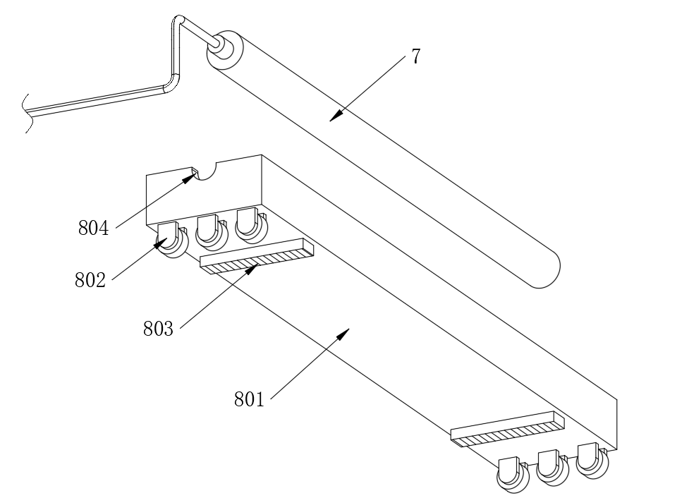
Figure 3. Drive Component Diagram
3.4. Electric Heating Elements for Tunnel Entrance Snow-Melting Systems - Working Principle
The working principle of the electric heating road snow-melting technology involves installing heating elements, such as carbon fiber heating wires, beneath or inside the road surface. These heating elements convert electrical energy into thermal energy, increasing the road surface temperature to melt ice and snow. During construction or renovation, special carbon fiber heating wires are embedded between the upper and lower layers of the asphalt road surface. When in operation, electrical energy is converted into thermal energy, raising the temperature of the equipment. The ice and snow melt as the road surface temperature increases, forming liquid water that flows into side ditches or gutters along the equipment's slope, thus reducing snow and ice accumulation on the road surface. An intelligent control system is employed to achieve energy-saving and efficient snow melting, automatically adjusting the heating power and duration based on snow accumulation on the road and weather conditions. Compared to traditional methods like manual ice and snow removal or the application of snow-melting agents, this technology offers certain advantages, including better snow and ice removal effectiveness, proactive snow melting, and savings in manpower and resources.
This device includes an installation box, multiple heating pipes, and multiple placement components. One end of the installation box is open, and a placement groove is provided at the upper end near the open side of the installation box. The inner wall bottom end of the installation box is fixedly connected with a pair of symmetrical positioning blocks. The placement components include a placement box that matches the heating pipes, with a drive component set between a pair of positioning blocks.
At the bottom end of the placement box, a pair of symmetrical rollers is fixedly connected. The upper end of the positioning block has a positioning groove that matches the rollers. A cable storage compartment is formed between the end of the positioning block away from the other and the inner wall of the installation box. A pair of cable slots that match the heating pipes is provided at the top end of the placement box.
The drive component includes a servo motor and a pair of positioning rods. The servo motor is mounted at one end of the positioning block, and the pair of positioning rods is set on both sides of the installation box cavity. One end of one of the positioning rods is fixedly connected to the output end of the servo motor, while the other end is rotatably connected to the positioning block. The other positioning rod has both ends rotatably connected to the pair of positioning blocks.
A pair of sprockets is fixedly connected to the outer ends of the pair of positioning rods. A chain is installed at the outer end of the sprockets. Multiple sprockets are connected through the chain, and the bottom end of the placement box is fixedly connected with a rack that matches the chain.
3.5. Benefits
Compared to existing technologies, the advantages of this technical solution are as follows:
In this solution, when installing and removing multiple heating pipes, the user only needs to turn on the road switch located next to the road. This allows the drive component to place multiple placement components from the placement groove into the installation box's inner cavity or remove them all from the placement groove. There is no need to excavate the road surface at the tunnel entrance, and it does not affect normal road traffic operations. This greatly facilitates installation and maintenance work, reduces maintenance costs, and minimizes the impact on traffic flow.
4. Specific Implementation
Below, with reference to the accompanying drawings in the embodiment of this technical solution, the technical solution of this embodiment will be described clearly and completely. It is apparent that the described technical solution is only one of the embodiments, and not all of the embodiments based on this technical solution.
In the description of this technical solution, it should be noted that terms such as "upper," "lower," "inner," "outer," "top/bottom end," etc., refer to positional or orientation relationships based on the orientations or positions shown in the drawings, and are only for convenience in describing the present invention and simplifying the description. They do not indicate or imply that the described device or component must have a specific orientation or be constructed and operated in a specific orientation. Additionally, terms such as "first," "second," etc., are used merely for descriptive purposes and should not be understood as indicating or implying relative importance.
In the description of this technical solution, unless explicitly specified and limited otherwise, terms such as "install," "provided with," "mounted on/connected to," etc., should be understood broadly. For example, "connected" can mean fixed connection, detachable connection, or integral connection; it can be mechanical or electrical; it can be direct or indirect through intermediate media, or it can be internal communication between two components. For those skilled in the art, the specific meaning of these terms in this invention can be understood based on the context.
|
|
Figure 4. Main Structure Schematic Diagram | Figure 5. Sliding Box Working Component Schematic Diagram |
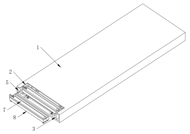

Referring to Figure 5, a tunnel mouth snow-melting system electric heating element includes an installation box (1), multiple heating tubes (7), and multiple placement components (8). One end of the installation box (1) is open, and a placement slot (2) is provided at the upper end near the open side of the installation box (1). The bottom end of the inner wall of the installation box (1) is fixedly connected to a pair of symmetrically positioned limiting blocks (3). The placement components (8) include a placement box (801), and the heating tubes (7) are matched with the placement box (801). A driving component (6) is positioned between the pair of limiting blocks (3).
Referring to Figure 4, the user can first horizontally embed the installation box (1) under the road surface at the tunnel mouth. An openable road surface switch that matches the placement slot (2) is set above the placement slot (2). The user then installs multiple heating tubes (7) onto multiple placement components (8), and subsequently places the placement components (8) one by one into the installation box (1) from the placement slot (2). During the process of placing the components (8), the driving component (6) moves the placement components (8) further into the interior of the installation box (1) until the heating tubes (7) are closely arranged inside the installation box (1). With this arrangement, when multiple heating tubes (7) are activated simultaneously, the heat emitted can be conducted to the upper end of the installation box (1) and then to the road surface above, thereby heating and accelerating the melting of snow on the road surface. The user can install and remove multiple heating tubes (7) simply by opening the road surface switch located beside the road. This allows the driving component (6) to move the placement components (8) into the interior of the installation box (1) from the placement slot (2) or remove them entirely without needing to excavate the road surface at the tunnel mouth, thus not affecting the normal operation of road traffic.
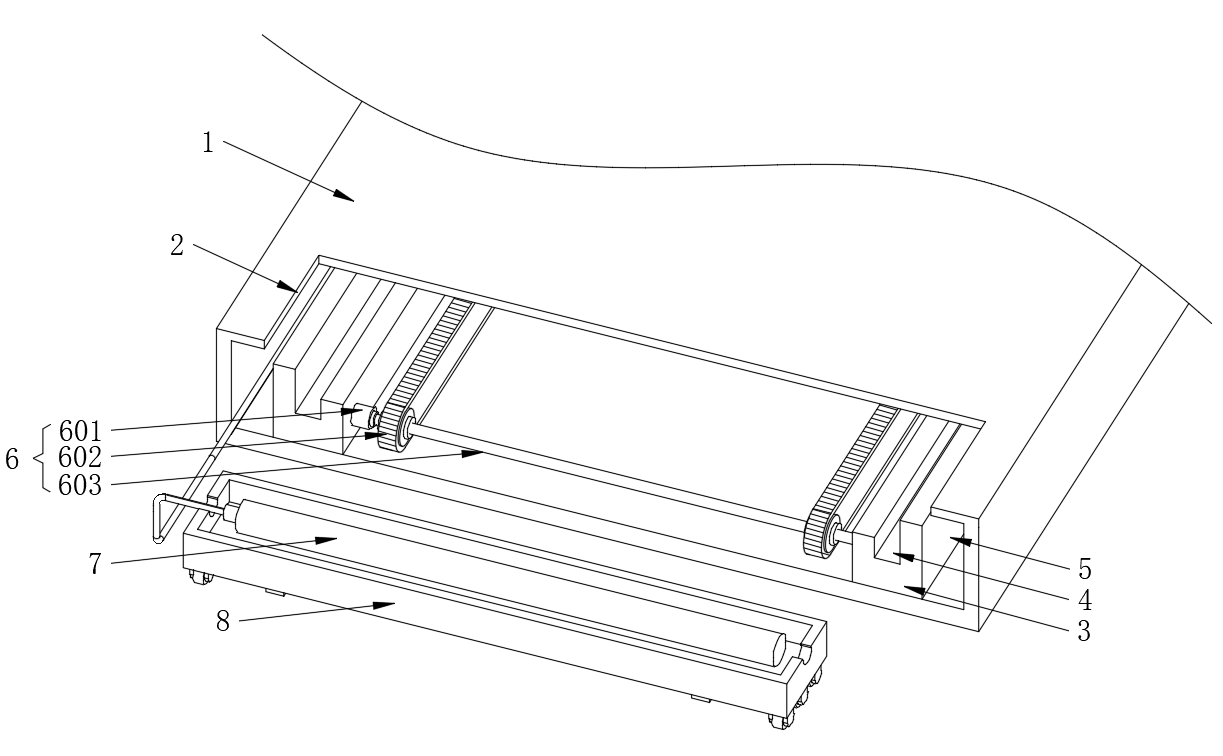
Figure 6. Partial Structure Schematic Diagram
Referring to Figure 6, the bottom end of the placement box (801) is fixedly connected to a pair of symmetrically positioned rollers (802). The upper end of the limiting block (3) is provided with a limiting slot (4) that matches the rollers (802). A pair of limiting blocks (3) forms a wire storage chamber (5) between their mutually distant ends and the inner wall of the installation box (1). The top end of the placement box (801) is provided with a pair of wire placement grooves (804) that match the heating tubes (7).
When installing multiple heating tubes (7), the user first places the heating tubes (7) inside the placement box (801). The placement box (801) is then inserted into the interior of the installation box (1) from the placement slot (2), causing the pair of rollers (802) at the bottom end of the placement box (801) to enter the pair of limiting slots (4). This allows the placement box (801) to slide on the limiting blocks (3) via the rollers (802). At the same time, the user can place the cables connected to the heating tubes (7) in the wire placement grooves (804) and then insert the cables into the wire storage chamber (5). With this setup, when the placement box (801) moves into the deeper part of the installation box (1), the cables connected to the heating tubes (7) remain in the wire storage chamber (5), avoiding direct contact between the cables and the heating tubes (7), thus preventing damage to the cables from the heat of the heating tubes (7).
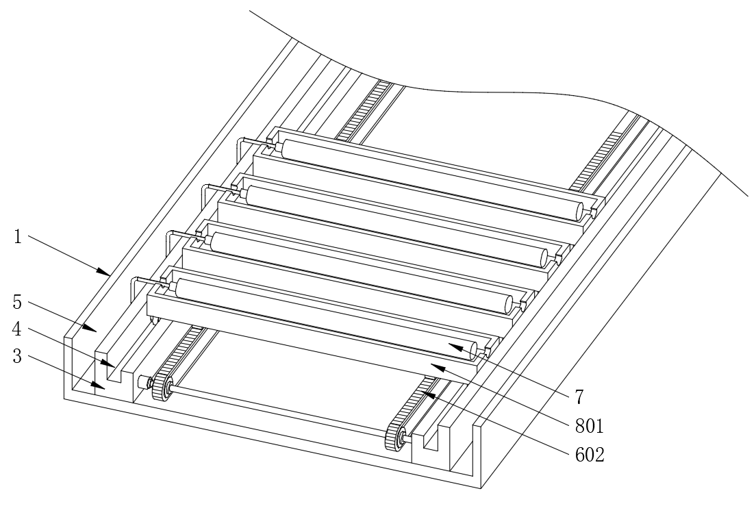
Figure 7. Internal Structure Schematic Diagram
Referring to Figure 7, the driving component (6) includes a servo motor (601) and a pair of limiting rods (603). The servo motor (601) is mounted at one end of the limiting block (3). The pair of limiting rods (603) are positioned on both sides of the inner cavity of the installation box (1). One limiting rod (603) is fixedly connected to the output end of the servo motor (601), and the end of the limiting rod (603) away from the servo motor (601) is rotatably connected to the limiting block (3). The other limiting rod (603) is rotatably connected at both ends to the pair of limiting blocks (3). Each external end of the pair of limiting rods (603) is fixedly connected to a pair of sprockets. A chain (602) is mounted on the external end of each sprocket, and multiple sprockets are connected by the chain (602). The bottom end of the placement box (801) is fixedly connected to a rack (803) that matches the chain (602).
When the user places the placement box (801) on the pair of limiting blocks (3), the pair of racks (803) at the bottom end of the placement box (801) engages with the pair of chains (602). At this point, the user activates the servo motor (601) to drive the limiting rods (603) to rotate, which in turn rotates the pair of sprockets. With the cooperation of the other limiting rod (603) and another pair of sprockets above it, the chains (602) are driven to move. The movement of the chains (602) drives the racks (803) to move, thereby causing the placement box (801) to slide on the limiting blocks (3) via the rollers (802) and move deeper into the installation box (1). The user then sequentially places additional placement boxes (801) closely behind the previous one into the installation box (1). This allows multiple placement boxes (801) carrying heating tubes (7) to be delivered into the interior of the installation box (1), completing the installation of the heating tubes (7). Similarly, by reversing the direction of rotation of the servo motor (601), the user can remove the multiple placement boxes (801) one by one from the placement slot (2).
5. Working Principle
When in use, the user can first horizontally embed the installation box (1) under the road surface at the tunnel mouth. An openable road surface switch that matches the placement slot (2) is set above the placement slot (2). After opening the road surface switch, the user places multiple heating tubes (7) in the interior of multiple placement boxes (801), then inserts the placement boxes (801) into the interior of the installation box (1) from the placement slot (2). The rollers (802) at the bottom end of the placement boxes (801) will enter the limiting slots (4). At the same time, the cables connected to the heating tubes (7) are placed in the wire placement grooves (804) and then inserted into the wire storage chamber (5). After placing the placement box (801) on the limiting blocks (3), the racks (803) at the bottom end of the placement box (801) will engage with the chains (602). The user then activates the servo motor (601), which drives the limiting rods (603) to rotate and in turn rotates the sprockets, causing the chains (602) to move. The movement of the chains (602) drives the racks (803) and causes the placement box (801) to slide via the rollers (802) on the limiting blocks (3) and move deeper into the installation box (1). The user continues to place additional placement boxes (801) into the installation box (1), thereby completely installing the heating tubes (7). Conversely, by reversing the direction of the servo motor (601), the user can remove the placement boxes (801) from the placement slot (2). The user then closes the road surface switch and activates the heating tubes (7). The heat emitted is conducted to the upper end of the installation box (1) and then to the road surface above, thereby heating and accelerating the melting of snow on the road surface.
The above describes the preferred embodiment.
6. Conclusion
This paper introduces the de-icing and snow melting technology for tunnel and bridge openings based on the existing electric heating snow melting and de-icing technology, proposing the energy requirements and corresponding methods for de-icing and snow melting at tunnel and bridge openings [7]. Based on case studies [12], the feasibility and rationality of the power supply operation of carpet-style electric heating elements have been preliminarily concluded as follows:
1. Maturity of the Technology: The electric heating road snow melting technology has already been applied in some practical projects and has achieved good results. This project adjusts and optimizes the existing technology based on actual engineering applications, effectively solving the problem of road surface icing when installed at highway tunnel and bridge locations. The control system is precise: it includes a complete and mature precise control system [13], ensuring uniformity and stability in road surface temperature. The project uses an intelligent control system, based on the Internet of Things, to achieve remote monitoring and control [14].
2. Stable Energy Supply: This technology requires electricity as an energy source. The power supply is relatively stable and can be supplemented by renewable energy sources such as solar energy, so the energy supply issue will not become a bottleneck for this technology.
3. Cost-Effectiveness: Although the initial investment for electric heating road snow melting technology is relatively high, its maintenance costs and labor operation costs are relatively low. It can effectively reduce traffic accidents and improve road capacity. Therefore, from a long-term perspective, this technology has certain cost-effectiveness.
4. Energy Saving and Environmental Protection: Compared with traditional snow melting methods, this technology does not require the use of chemical de-icing agents, which would not pollute the environment. It can also save energy and reduce the emission of greenhouse gases such as carbon dioxide.
5. Extension of Road Surface Lifespan: Chemical de-icing agents can corrode the road surface, shortening its lifespan. In contrast, the electric heating road snow melting technology does not damage the road surface but reduces the freeze-thaw cycle, extending the road surface's lifespan. Once installed, it forms an integrated structure with the road surface and does not require further excavation for maintenance, avoiding damage.
6. Improved Road Capacity and Safety: Road surface icing can lead to decreased road capacity. Using this technology can quickly eliminate road surface icing, improving road capacity and reducing traffic congestion. Icy road surfaces are a major cause of traffic accidents. By using this snow melting and de-icing technology, road surface icing can be effectively eliminated, enhancing road safety and reducing traffic accidents.
7. In Summary, this technology has significant snow melting capability and timeliness. It can be installed during the construction process based on actual road conditions and does not require further damage to the road surface during future use and maintenance. It does not affect normal traffic capacity. Further experimental research is needed on the temperature distribution and heat effectiveness of carpet-style snow melting and de-icing devices under different burial depths and road surface material conditions.
References
[1]. Zhou Xiaopeng. Study on the Ice Melting Efficiency of Road Deicing Agents and the Law of Secondary Freezing [D]. Supervisor: Guo Dedong; Wei Jincheng. Shandong Jiaotong University, 2020. DOI: 10.27864/d.cnki.gsjtd.2020.000019
[2]. Tan Yiqiu, Zhang Chi, Xu Huining, Tian Dong. Review of Active Snow and Ice Removal Pavement Snow Melting and Ice Melting Characteristics and Road Performance [J]. China Journal of Highway and Transport, 2019, 32 (04): 1-17.
[3]. Cao Haibo, Chen Tuanjie, Lu Jingjing, Chen Shi. Feasibility Study on Pavement Self-Stress Ice-Breaking Paving Structure [J]. Modern Transportation Technology, 2011, 8 (02): 16-18+33.
[4]. Qiao Shizhe, Qin Hao, Huang Wanqing, Cao Mingming. Evaluation of Ice Melting Performance of Low Freezing Point Asphalt Concrete Pavement Based on Machine Vision [A]. China Association for Science and Technology, Ministry of Transport, Chinese Academy of Engineering, Hubei Provincial People's Government, 2022 World Transport Conference (WTC2022) Proceedings (Highway Engineering Section) [C]. Xihua University School of Energy and Power Engineering; Sichuan Provincial Traffic Survey and Design Institute Co., Ltd.; 2022: 172-179.
[5]. Liu Zhuangzhuang, Zhang Youwei, Ji Pengyu, Hao Yazhen, Li Lin. Review of Electric Heating Snow Melting Pavement Technology [J]. Journal of Chang'an University (Natural Science Edition), 2022, 42 (03): 14-25.
[6]. Huaihua City Transportation Bureau. Ensure Smooth Traffic with Deicing and Snow Melting in Huaihua, 2023-12-22.
[7]. Nagai N, Miyamoto S, NishiwaKi M, et al. Numerical Simulation of Snow Melting on Pavement Surface with Heat Dissipation Pipe Embedded [J]. Transactions of the Japan Society of Mechanical Engineers. B, 2008, 74(3): 640-647.
[8]. Han Ming. Optimization Study on the Design Scheme of Electric Heating Method for Road Snow Melting and Ice Melting [D]. Supervisor: Xiao Henglin. Hubei University of Technology, 2020.
[9]. Zhou Shuiwen, Pan Song, Zhang Rong. Application Practice of Intelligent Loop Heat Pipe Snow Melting on Sichuan-Jiuzhaigou Road [J]. Shanghai Highway, 2023, (04): 1-6+207.
[10]. Lu Guoju, Zhang Zherui, Zhao Yongfang, Zhang Meihong. Experimental Study on Snow Melting and Ice Melting with Carbon Fiber Heating Cable in Asphalt Concrete Surface Layer [J]. Scientific and Technological Innovation, 2023, (02): 196-200.
[11]. Chen Weijian. Brief Analysis of the Application of Electric Heat Tracing in Snow Melting of Marine Step Modules [J]. Mechatronics Information, 2019, (06): 5-6.
[12]. Ming Ruitao. Study on the Migration and Accumulation of Deicing Agents at Ski Resorts Based on SWAT Model [D]. Beijing University of Civil Engineering and Architecture, 2021. DOI: 10.26943/d.cnki.gbjzc.2021.000250.
[13]. Du Xingsen. Road and Bridge Maintenance System V1.0 [P] China Patent: 2024SR03128274, 2024-02-26.
[14]. Du Xingsen. Highway and Bridge Inspection System [Abbreviation: Highway and Bridge Inspection] V1.0 [P] China Patent: 2022SR0951652, 2022-07-20.
Cite this article
Du,X.;Zong,K.;Ma,C.;Li,J.;Qi,C. (2024). Research on electric heating green snow melting and anti-icing technology for tunnel, bridge, and culvert entrances. Applied and Computational Engineering,91,73-82.
Data availability
The datasets used and/or analyzed during the current study will be available from the authors upon reasonable request.
Disclaimer/Publisher's Note
The statements, opinions and data contained in all publications are solely those of the individual author(s) and contributor(s) and not of EWA Publishing and/or the editor(s). EWA Publishing and/or the editor(s) disclaim responsibility for any injury to people or property resulting from any ideas, methods, instructions or products referred to in the content.
About volume
Volume title: Proceedings of the 2nd International Conference on Functional Materials and Civil Engineering
© 2024 by the author(s). Licensee EWA Publishing, Oxford, UK. This article is an open access article distributed under the terms and
conditions of the Creative Commons Attribution (CC BY) license. Authors who
publish this series agree to the following terms:
1. Authors retain copyright and grant the series right of first publication with the work simultaneously licensed under a Creative Commons
Attribution License that allows others to share the work with an acknowledgment of the work's authorship and initial publication in this
series.
2. Authors are able to enter into separate, additional contractual arrangements for the non-exclusive distribution of the series's published
version of the work (e.g., post it to an institutional repository or publish it in a book), with an acknowledgment of its initial
publication in this series.
3. Authors are permitted and encouraged to post their work online (e.g., in institutional repositories or on their website) prior to and
during the submission process, as it can lead to productive exchanges, as well as earlier and greater citation of published work (See
Open access policy for details).
References
[1]. Zhou Xiaopeng. Study on the Ice Melting Efficiency of Road Deicing Agents and the Law of Secondary Freezing [D]. Supervisor: Guo Dedong; Wei Jincheng. Shandong Jiaotong University, 2020. DOI: 10.27864/d.cnki.gsjtd.2020.000019
[2]. Tan Yiqiu, Zhang Chi, Xu Huining, Tian Dong. Review of Active Snow and Ice Removal Pavement Snow Melting and Ice Melting Characteristics and Road Performance [J]. China Journal of Highway and Transport, 2019, 32 (04): 1-17.
[3]. Cao Haibo, Chen Tuanjie, Lu Jingjing, Chen Shi. Feasibility Study on Pavement Self-Stress Ice-Breaking Paving Structure [J]. Modern Transportation Technology, 2011, 8 (02): 16-18+33.
[4]. Qiao Shizhe, Qin Hao, Huang Wanqing, Cao Mingming. Evaluation of Ice Melting Performance of Low Freezing Point Asphalt Concrete Pavement Based on Machine Vision [A]. China Association for Science and Technology, Ministry of Transport, Chinese Academy of Engineering, Hubei Provincial People's Government, 2022 World Transport Conference (WTC2022) Proceedings (Highway Engineering Section) [C]. Xihua University School of Energy and Power Engineering; Sichuan Provincial Traffic Survey and Design Institute Co., Ltd.; 2022: 172-179.
[5]. Liu Zhuangzhuang, Zhang Youwei, Ji Pengyu, Hao Yazhen, Li Lin. Review of Electric Heating Snow Melting Pavement Technology [J]. Journal of Chang'an University (Natural Science Edition), 2022, 42 (03): 14-25.
[6]. Huaihua City Transportation Bureau. Ensure Smooth Traffic with Deicing and Snow Melting in Huaihua, 2023-12-22.
[7]. Nagai N, Miyamoto S, NishiwaKi M, et al. Numerical Simulation of Snow Melting on Pavement Surface with Heat Dissipation Pipe Embedded [J]. Transactions of the Japan Society of Mechanical Engineers. B, 2008, 74(3): 640-647.
[8]. Han Ming. Optimization Study on the Design Scheme of Electric Heating Method for Road Snow Melting and Ice Melting [D]. Supervisor: Xiao Henglin. Hubei University of Technology, 2020.
[9]. Zhou Shuiwen, Pan Song, Zhang Rong. Application Practice of Intelligent Loop Heat Pipe Snow Melting on Sichuan-Jiuzhaigou Road [J]. Shanghai Highway, 2023, (04): 1-6+207.
[10]. Lu Guoju, Zhang Zherui, Zhao Yongfang, Zhang Meihong. Experimental Study on Snow Melting and Ice Melting with Carbon Fiber Heating Cable in Asphalt Concrete Surface Layer [J]. Scientific and Technological Innovation, 2023, (02): 196-200.
[11]. Chen Weijian. Brief Analysis of the Application of Electric Heat Tracing in Snow Melting of Marine Step Modules [J]. Mechatronics Information, 2019, (06): 5-6.
[12]. Ming Ruitao. Study on the Migration and Accumulation of Deicing Agents at Ski Resorts Based on SWAT Model [D]. Beijing University of Civil Engineering and Architecture, 2021. DOI: 10.26943/d.cnki.gbjzc.2021.000250.
[13]. Du Xingsen. Road and Bridge Maintenance System V1.0 [P] China Patent: 2024SR03128274, 2024-02-26.
[14]. Du Xingsen. Highway and Bridge Inspection System [Abbreviation: Highway and Bridge Inspection] V1.0 [P] China Patent: 2022SR0951652, 2022-07-20.