


1. Introduction
Direct current (DC) motor speed control has been an application area for many meta-heuristics algorithms as a real-world engineering application within the last decade since it provides an observable test bed for performance evaluations and comparisons [1].DC motors have many good characteristics, such as high starting torque, high response performance, and easy linear control, and have long been popular in the industrial field[2]. Traditional control methods may be unable to cope with the impact of load changes and other factors, resulting in performance degradation or system instability.[3]. Despite these advancements, there are notable research gaps in optimizing control algorithms for complex electromechanical systems and integrating advanced technologies like artificial intelligence to improve decision-making processes.DC motors also have an urgent role in the convenience of the use of electronic household appliances [4].
The specific research topic of this paper revolves around the application of microcomputers in controlling and monitoring electromechanical systems, particularly focusing on electric motor control and monitoring. Specifically, the study delves into the application of proportional differential controllers in regulating the angular motion of DC electric motors.
It is a known fact that most industrial control loops are of PI/PID type [5]. So, the research methodology employed in this study includes programming microcomputer systems to control and monitor electric motors effectively. This involves the utilization of sensors to collect data for feedback control, enabling the analysis of results to optimize system performance and ensure operational efficiency. This research holds significant importance in providing valuable insights into the practical application of microcomputer control in electromechanical systems, thereby contributing to advancements in the field. It is a foundation for enhancing automation, efficiency, and precision across diverse industries.
2. Basic theories and advantages of PID control
P control (proportional control) is a direct output of the corresponding size according to the deviation, which can respond more quickly and accurately.
I control (Integral control) can eliminate steady-state errors and improve system accuracy. The integral gain Ki determines the zero deviation tracking capability of the system.
D control (differential control) is based on the deviation rate of change output control quantity, can predict the future change trend of the system, and improve the response speed and stability of the system.
The PD control circuit measures the actual speed or Angle of the motor, compares it with the target set value, and generates a deviation signal. Then, the deviation is amplified by the proportional link, the deviation trend is predicted by the differential link, the control quantity is obtained comprehensively, the motor input is adjusted by feedback, and the accurate control of the motor is realized. PD control (proportional-differential control) combines P control and D control, which can not only respond to deviation quickly but also predict system changes and obtain better dynamic performance and stability.
3. Experimental process
3.1. Circuit construction
The main idea of the circuit is to control the amplification and reduction of the current when the current passes through the operational amplifier and to ensure the control of the response time and fluctuations of the circuit through the resistance and capacitance, as well as the safety of the entire circuit.
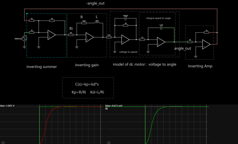
Figure 1. Circuit design using Falstad
According to the formula in Figure 1, the relationship between C(s) and \( {K_{p}} \) and \( {K_{d}} \) is linear.
The most basic module, that is, the module related to \( {K_{p}} \) and \( {K_{d}} \) , is composed of a signal amplifier, two resistors and a capacitor.
By changing different \( {K_{p}} \) and \( {K_{d}} \) can get different function images.
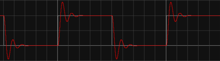
Figure 2. Image of \( {K_{p}} \) =10, \( {K_{d}} \) =0.05
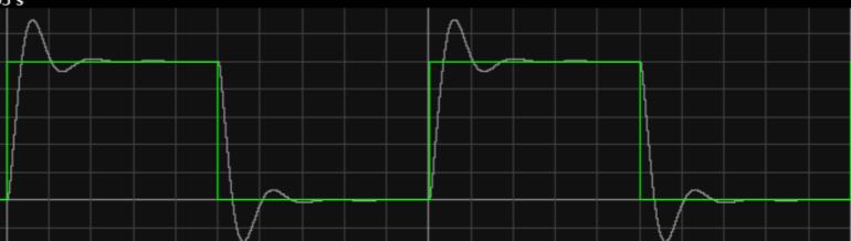
Figure 3. Image of \( {K_{p}} \) =4, \( {K_{d}} \) =0.05
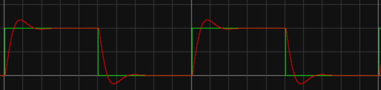
Figure 4. Image of \( {K_{p}} \) =2, \( {K_{d}} \) =0.05
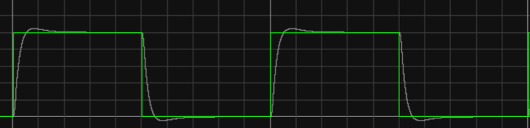
Figure 5. Image of \( {K_{p}} \) =2, \( {K_{d}} \) =0.1
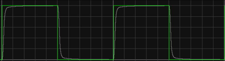
Figure 6. Image of \( {K_{p}} \) =2, \( {K_{d}} \) =0.2
It is possible to obtain a much better result by studying each particular control problem in detail and applying it [6]. Compared with images 2-4, only \( {K_{p}} \) is changed, and it is found that the response speed of the system and the change of the wave are both improved. Increasing \( {K_{p}} \) is important to reduce deviation, speed up response time, and reduce adjustment time [7]; compared with images 4-6, only \( {K_{d}} \) is changed, and it is found that the response speed has no obvious change, but the fluctuation change is more obvious, which has a negative growth relationship with \( {K_{d}} \) .To raise KD, will make the transient response become slower but cannot improve a steady state error [8]. Although this kind of controller is very robust to parameter variations, it still presents an error in steady state operation [9].
3.2. PID system improvement
For the improvement of the PID system, it choose to design the transient response first and then design the steady-state response error. However, this method also has some disadvantages, and the response will become slower when the steady-state response error is carried out.
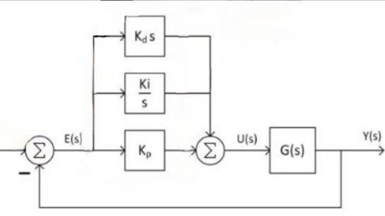
Figure 7. PID system generation process
The first zero is determined by the PI compensator, and the second zero is determined by the PD compensator.
\( D(s)={K_{d}}S+\frac{{K_{i}}}{S}+{K_{p}}=\frac{{K_{d}}{S^{2}}+{K_{i}}+{K_{p}}S}{S} \) (1)
About designing the PID program:
• Find the pole position of the closed loop to ensure the transient response.
• Design a PD controller to prevent closed loop poles as required.
• Simulate the PD closed-loop compensation system and carry out necessary iterations.
• A PI compensator is added to the system to determine the ideal pole position.
• Determine the specific PID parameters, namely the three values ( \( {K_{d}} \) 、 \( {K_{i}} \) 、 \( {K_{p}} \) ) in the figure above.
• Simulate the PID closed-loop compensation system and carry out the necessary iteration.Instead of using PI controller, PID is being used, as derivative part of the controller contributes to reducing overshoot.[10]
Set:
\( {t_{S}}=2sec \) (2)
\( \%OS≈20\% \) (3)
So:
\( σ≈\frac{46}{{t_{S}}}=23 \) (4)
\( τ≈\frac{ln{0.2}}{\sqrt[]{{π^{2}}+{ln^{2}}0.2}}=0.46 \) (5)
\( {ω_{d}}=\frac{σ}{τ}\sqrt[]{1-{τ^{2}}}=4.49 \) (6)
Convert to PID(add a zero):
\( ∠{D_{pd}}{G_{({S_{1}})}}=18{0^{°}} \) (7)
\( {G_{({S_{1}})}}=-{∅_{1}}-{∅_{2}}-{∅_{3}}=57.8° \) (8)
\( {Z_{pd}}=Re \) (9)
\( tan{({ψ_{pd}})}=\frac{4.49}{{Z_{pd}}-2.3} \) (10)
\( k=|\frac{1}{{D_{pd({S_{1}})}}{G_{({S_{1}})}}}|=1.55 \) (11)
The open-loop pole at zero will become a closed-loop pole near \( {Z_{pi}} \) , which means that the closed-loop pole error integral of a small \( {Z_{pi}} \) will also grow very slowly. It can also be said that a small \( {Z_{pi}} \) has little influence on the PD compensation trace.
\( {D_{(S)}}=\frac{k(S+0.8)(S+5.13)}{S}=\frac{{K_{d}}{S^{2}}+{K_{i}}+{K_{p}}S}{S} \) (12)
Find: \( {K_{d}}=1.15, {K_{i}}=4.718, {K_{p}}=6.817 \)
Lead-lag compensation:
\( {D_{(S)}}=\frac{k(S+{Z_{lead}})(S+{Z_{lag}})}{(S+{P_{lead}})(S+{P_{lag}})} \) (13)
Lead-lag design steps:
• To ensure timely delivery of transient responses, the closed-loop pole position should be ensured.
• Design the lead compensator.
• Simulate the compensation system and iterate when necessary.
• Evaluate the steady-state error performance of the system. (Purpose is to determine the margin of error)
• Design lag compensator to compensate for steady-state error performance.
• Simulate the Lead-lag compensation system again and iterate when necessary.
4. Analog circuit
By using Arduino Uno R3 to simulate input pins and output pins and using power supply to simulate the actual application of the real circuit, using oscilloscope to record the waveform issued by the circuit, using operational amplifier (opAmp) to control the current, it can amplify the input signal into a higher output signal. At the same time, it also has a high input impedance and a low output impedance, so that it can be used in the circuit as a signal amplification, filtering, shaping, using resistors and capacitors to achieve the appropriate \( {K_{p}} \) and \( {K_{d}} \) to optimize the response speed and the system.
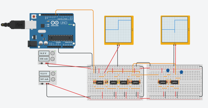
Figure 8. Simulation experiment
The above two images need to be corrected, and the possible reason is that \( {K_{p}} \) and \( {K_{d}} \) do not fit.The correct image would be an oscilloscope displaying a straight line waveform and an oscilloscope displaying an image similar to the one simulated by Falstad. This section can also judge whether Tinkercad is linked correctly and the parameters are selected correctly.
5. Conclusion
By adjusting the parameters of the PID controller, it successfully reduce the phenomenon of over harmonic oscillation of the system. After repeated experiments and parameter adjustment, the best combination of P and D parameters is found, which makes the system response more stable and accurate. By identifying and correcting the model of the DC motor system, it further improve the control precision and performance of the system. The corrected model is closer to the actual system, which is helpful in improving the design and implementation of the control scheme. Through the collection and analysis of experimental data, it verify the performance optimization effect of the improved PID controlled DC motor system. The system response is more stable and accurate, and it is more resistant to parameter changes and interference. These improvement measures provide useful experience and enlightenment for further optimizing control scheme and improving system performance. In future studies, it will continue to explore more advanced control strategies and technologies to further improve the control effect and application performance of DC motor systems.
References
[1]. Ekinci, Hekimoğlu, B., & Izci, D. (2021). Opposition based Henry gas solubility optimization as a novel algorithm for PID control of DC motor. Engineering Science and Technology, an International Journal, 24(2), 331–342. https://doi.org/10.1016/j.jestch.2020.08.011
[2]. J. B. Wang(2001), Control of Electric Machinery. Gau Lih Book Co., Ltd, Taipei Taiwan.
[3]. Yuzhe Li(2023),PD control-based constant speed control system of DC motor 2023.PD control-based constant speed control system of DC motor | AIP Conference Proceedings | AIP Publishing
[4]. Prakosa, J.A., Gusrialdi, A., Kurniawan, E. et al. Experimentally robustness improvement of DC motor speed control optimization by H-infinity of mixed-sensitivity synthesis. Int. J. Dynam. Control 10, 1968–1980 (2022). https://doi.org/10.1007/s40435-022-00956-y
[5]. Åström K, Hägglund T. Advanced PID control. The Instrumentation, Systems, and Automation Society (ISA); 2006, ISBN:1-55617-942-1.
[6]. Tepljakov, Gonzalez, E. A., Petlenkov, E., Belikov, J., Monje, C. A., & Petráš, I. (2016). Incorporation of fractional-order dynamics into an existing PI/PID DC motor control loop. ISA Transactions, 60, 262–273. https://doi.org/10.1016/j.isatra.2015.11.012
[7]. Li. (2024). PD control-based constant speed control system of DC motor. AIP Conference Proceedings, 3144(1). https://doi.org/10.1063/5.0215486
[8]. Guoshing Huang, & Shuocheng Lee. (2008). PC-based PID speed control in DC motor. 2008 International Conference on Audio, Language and Image Processing, 400–407. https://doi.org/10.1109/ICALIP.2008.4590052
[9]. Monteiro, Pereira, W. C. A., Santana, M. P., Almeida, T. E. P., Paula, G. T., & Santini, I. (2013). Anti-windup method for fuzzy PD+I, PI and PID controllers applied in brushless DC motor speed control. 2013 Brazilian Power Electronics Conference, 865–871. https://doi.org/10.1109/COBEP.2013.6785216
[10]. Dubravic, & Serifovic-Trbalic, A. (2022). Robustness Analysis of Legendre Orthonormal Functions Based Model Predictive Control and PID Control of DC Motor. 2022 XIV International Symposium on Industrial Electronics and Applications (INDEL), 1–5. https://doi.org/10.1109/INDEL55690.2022.9965538
Cite this article
Zhang,H. (2024). Improved PID control of DC motor. Applied and Computational Engineering,101,118-123.
Data availability
The datasets used and/or analyzed during the current study will be available from the authors upon reasonable request.
Disclaimer/Publisher's Note
The statements, opinions and data contained in all publications are solely those of the individual author(s) and contributor(s) and not of EWA Publishing and/or the editor(s). EWA Publishing and/or the editor(s) disclaim responsibility for any injury to people or property resulting from any ideas, methods, instructions or products referred to in the content.
About volume
Volume title: Proceedings of the 2nd International Conference on Machine Learning and Automation
© 2024 by the author(s). Licensee EWA Publishing, Oxford, UK. This article is an open access article distributed under the terms and
conditions of the Creative Commons Attribution (CC BY) license. Authors who
publish this series agree to the following terms:
1. Authors retain copyright and grant the series right of first publication with the work simultaneously licensed under a Creative Commons
Attribution License that allows others to share the work with an acknowledgment of the work's authorship and initial publication in this
series.
2. Authors are able to enter into separate, additional contractual arrangements for the non-exclusive distribution of the series's published
version of the work (e.g., post it to an institutional repository or publish it in a book), with an acknowledgment of its initial
publication in this series.
3. Authors are permitted and encouraged to post their work online (e.g., in institutional repositories or on their website) prior to and
during the submission process, as it can lead to productive exchanges, as well as earlier and greater citation of published work (See
Open access policy for details).
References
[1]. Ekinci, Hekimoğlu, B., & Izci, D. (2021). Opposition based Henry gas solubility optimization as a novel algorithm for PID control of DC motor. Engineering Science and Technology, an International Journal, 24(2), 331–342. https://doi.org/10.1016/j.jestch.2020.08.011
[2]. J. B. Wang(2001), Control of Electric Machinery. Gau Lih Book Co., Ltd, Taipei Taiwan.
[3]. Yuzhe Li(2023),PD control-based constant speed control system of DC motor 2023.PD control-based constant speed control system of DC motor | AIP Conference Proceedings | AIP Publishing
[4]. Prakosa, J.A., Gusrialdi, A., Kurniawan, E. et al. Experimentally robustness improvement of DC motor speed control optimization by H-infinity of mixed-sensitivity synthesis. Int. J. Dynam. Control 10, 1968–1980 (2022). https://doi.org/10.1007/s40435-022-00956-y
[5]. Åström K, Hägglund T. Advanced PID control. The Instrumentation, Systems, and Automation Society (ISA); 2006, ISBN:1-55617-942-1.
[6]. Tepljakov, Gonzalez, E. A., Petlenkov, E., Belikov, J., Monje, C. A., & Petráš, I. (2016). Incorporation of fractional-order dynamics into an existing PI/PID DC motor control loop. ISA Transactions, 60, 262–273. https://doi.org/10.1016/j.isatra.2015.11.012
[7]. Li. (2024). PD control-based constant speed control system of DC motor. AIP Conference Proceedings, 3144(1). https://doi.org/10.1063/5.0215486
[8]. Guoshing Huang, & Shuocheng Lee. (2008). PC-based PID speed control in DC motor. 2008 International Conference on Audio, Language and Image Processing, 400–407. https://doi.org/10.1109/ICALIP.2008.4590052
[9]. Monteiro, Pereira, W. C. A., Santana, M. P., Almeida, T. E. P., Paula, G. T., & Santini, I. (2013). Anti-windup method for fuzzy PD+I, PI and PID controllers applied in brushless DC motor speed control. 2013 Brazilian Power Electronics Conference, 865–871. https://doi.org/10.1109/COBEP.2013.6785216
[10]. Dubravic, & Serifovic-Trbalic, A. (2022). Robustness Analysis of Legendre Orthonormal Functions Based Model Predictive Control and PID Control of DC Motor. 2022 XIV International Symposium on Industrial Electronics and Applications (INDEL), 1–5. https://doi.org/10.1109/INDEL55690.2022.9965538