


1. Introduction
In the context of increasingly severe energy and environmental issues, renewable energy sources like wind and solar power have gained widespread attention due to their renewability and non-polluting nature. However, the generation of renewable energy is significantly affected by environmental factors, leading to high variability and intermittency, which pose challenges for its development. As renewable energy and distributed generation become more prominent, there is an increasing demand for reliable and efficient small-scale dispatchable power units. This is because intermittent renewable sources like solar and wind cannot be easily controlled, causing fluctuations in the power supplied to the grid. Therefore, auxiliary systems and hybrid technologies are needed to ensure stable power output and meet demand [1, 2].
In this new power generation landscape, the local electricity supply systems, known as micro-grids (MG), work together to balance the local power system. Unlike the main grid, a micro-grid is a single controllable entity that can operate in grid-connected mode. Many studies have explored ways to enhance the stability and maximize the utilization of photovoltaic (PV) systems within micro-grids. For example, some researchers compare the advantages and disadvantages of various maximum power point tracking (MPPT) methods for PV systems [3]; others propose a model predictive control strategy for grid-connected PV inverters, achieving fast and precise control of inverter current and improving system performance [4]; another study introduces a hybrid energy storage system based on super-capacitors and batteries, along with control strategies to enhance power quality and grid dispatchability [5]; and one study addresses the issue of transient voltage stability in grid-connected inverters and suggests an inertia control strategy to effectively improve the fault ride-through capability of micro-grid voltage [6].
While these studies have improved the performance of grid-connected PV systems through various control algorithms, they often involve significant complexity and high deployment costs. Micro turbines, which can provide fast, reliable power to compensate for fluctuations in renewable energy, ensuring smooth output to meet energy demand, and offer advantages such as low emissions, high efficiency, easy installation, and simple maintenance [7], has now become an attractive approach to solve the afore-mentioned problems. Micro-turbine generator systems (MTGS) can deliver constant power with fast response times, high reliability, and flexible control, making them well-suited for integration with PV systems in hybrid micro-grid [8-10]. Therefore, this study focuses on the study of PV-MG hybrid power generation systems. It begins with the modeling of micro gas turbine generator systems, followed by an exploration of the operational and control framework of the hybrid power system. The feasibility and advantages of the proposed strategy is validated through mathematic modeling and simulation results.
2. Modeling of micro-turbine generator system
Fig. 1 illustrates the configuration of a grid-connected micro-turbine power generation system. This schematic features several key components, including a micro-turbine, a permanent magnet synchronous generator (PMSG), a rectifier, an inverter, a filter, and grid. In this setup, the micro-turbine compresses high-pressure air and combines it with fuel in the combustion chamber. Following the combustion process, the turbine is set in motion, which in turn causes the permanent magnet generator to spin and produce medium-frequency, medium-voltage alternating current (AC) power. Before it can be integrated into the distribution network, this AC power must first be transformed into standard frequency AC power via the inverter [11].
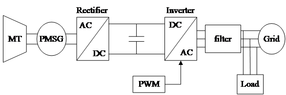
Figure 1. Structure diagram of micro-turbine grid-connected power generation system [11].
2.1. Modeling of micro-turbine
As previously stated, a micro-turbine can be viewed as a compact version of a gas turbine, functioning on the same foundational principles as an open-cycle gas turbine, comprising of a compressor, a combustion chamber, and a turbine, which together establish a fundamental Brayton cycle. Within this cycle, the compressor draws in air, which is then heated through the introduction of fuel in the combustion chamber, resulting in the production of high-temperature gases. Due to the low-pressure ratio in the cycle, the net electrical efficiency of a micro-turbine in a basic Brayton cycle is generally low [11]. Additionally, the power output is usually limited by the materials used in the turbine and the cost constraints of installing internal cooling systems in small-scale equipment like micro-turbines. To address this, industry practices include preheating the compressed air to reduce fuel consumption, which can improve the overall efficiency of the micro-turbine [11]. As shown in Fig. 2 [12], in a combined heat and power mode, the residual heat from the exhaust gases discharged from the heat exchanger can be transferred to heating water through another heat exchanger, or used for cooling in a cooler.
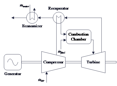
Figure 2. A standard micro-turbine cycle with a recuperator and economizer for combined heat and power generation [12].
Based on the basic model of a single-shaft, single-cycle gas turbine proposed by Rowen, the MT control system mainly includes three parts: speed control, temperature control, and acceleration control, as shown in Fig. 3 [12]. Speed control is the most basic method for adjusting the output power of the micro gas turbine. Acceleration control adjusts the fuel value according to the rate of speed change to reduce thermal shock to high-temperature gas path components. Temperature control primarily works by adjusting the fuel value to limit the temperature at the turbine inlet.
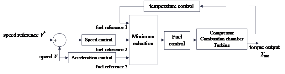
Figure 3. Control model of micro-turbines [12].
The reference commands from these three controls are processed through a minimum value selector, which chooses the smallest reference command as the fuel command sent to the fuel control system. This command then adjusts the fuel control valve, changing the fuel amount to regulate the output mechanical torque. Under normal operating conditions, the speed reference command is usually the smallest, meaning the speed control system is the primary regulator. However, in special situations, temperature control adjusts the exhaust temperature by changing the fuel amount to keep it within a certain range, and acceleration control acts during rapid load reduction or load shedding to prevent excessive rotor acceleration that could threaten the safety of the unit. The mechanical torque Tme generated by the fuel combustion that drives the turbine's rotation and the exhaust gas temperature T can be described by the following equations:
\( {T_{me}}={T_{ref}}-700(1-{ω_{f1}})+550(1-{ω_{e}}) \) (1)
\( T=KHHV({ω_{f2}}-0.23)+0.5(1-{ω_{e}}) \) (2)
where KHHV is the coefficient related to the thermal value of the airflow in the combustion chamber, typically set to 1.3. Tref is the reference value for the exhaust gas temperature, ωe is the electromagnetic speed of the engine rotor, ωf1 is the temperature at the exhaust port, and ωf2 is the fuel flow rate entering the turbine.
2.2. Modeling of PMSG
PMSG has advantages such as a simple structure, high efficiency, high reliability, and high power density, making it an important component of micro-turbine generator systems. Its mathematical modeling is usually done in the dq coordinate system, where the three-phase AC quantities are converted into DC quantities to simplify analysis and control. The stator voltage equation of the PMSG in the d-q axis is given by:
\( {v_{d}}={R_{s}}{i_{d}}+{L_{d}}\frac{d{i_{d}}}{dt}-{L_{q}}p{ω_{e}}{i_{q}} \) (3)
\( {v_{q}}={R_{s}}{i_{q}}+{L_{q}}\frac{d{i_{q}}}{dt}+{L_{d}}p{ω_{e}}{i_{d}}+λp{ω_{e}} \) (4)
where Rs is the stator resistance, Ld and Lq are the inductances along the d-axis and q-axis, respectively, λ is the magnetic flux generated by the permanent magnet, p is the number of pole pairs, and vd and vq are the voltages along the d-axis and q-axis, respectively. The electromagnetic torque Te equation is given by
\( {T_{e}}=1.5p[λ{i_{q}}+({L_{d}}-{L_{q}}){i_{d}}{i_{q}}] \) (5)
and the dynamic equation of the generator rotor is
\( \frac{d{ω_{r}}}{dt}=\frac{1}{J}({T_{e}}-{T_{me}}) \) (6)
where ωr is the mechanical speed of the engine rotor, and J is the rotor's moment of inertia.
2.3. Modeling of inverter
Inverter is the key component for connecting the MTGS to the grid. When the MTGS operates in grid-connected mode, the inverter uses PQ control to reduce the impact on the main grid. It controls power exchange with the grid according to the specified power output, with the main grid providing voltage and frequency support. Additionally, since the inverter's output at the grid frequency usually contains harmonics, an LC filter is typically installed at the inverter's output to filter out high-frequency harmonics near the switching frequency, keeping the total harmonic distortion (THD) below 5%. The inverter power generation model is shown in Fig. 4.
In the dq coordinate, the power on the inverter's AC side is given by:
\( \begin{cases} \begin{array}{c} {P^{*}}=\frac{3}{2}({u_{d}}{i_{d}}+{u_{q}}{i_{q}}) \\ {Q^{*}}=\frac{3}{2}({u_{q}}{i_{d}}-{u_{d}}{i_{q}}) \end{array} \end{cases} \) (7)
where ud is the grid voltage, and id is the grid current. Apply the Park transformation on the grid voltage, and use a grid voltage-oriented vector control, the d-axis is aligned with the grid voltage vector. This makes uq equal to 0 and ud a constant value. At this point, the power depends only on the current values, and the current reference values id* and iq* can be calculated from the power reference values P*and Q* as follows:
\( \begin{cases} \begin{array}{c} {P^{*}}=\frac{3}{2}{u_{d}}{i_{d}} \\ {Q^{*}}=-\frac{3}{2}{u_{d}}{i_{q}} \end{array} \end{cases} ⇒ \begin{cases} \begin{array}{c} {{i_{d}}^{*}}=\frac{2{P^{*}}}{3{u_{d}}} \\ {{i_{q}}^{*}}=-\frac{2{Q^{*}}}{3{u_{d}}} \end{array} \end{cases} \) (8)
From Eq. (8), the PQ control block diagram is illustrated in Fig. 5. Based on the active and reactive power reference values, the inner loop reference currents can be calculated. Through feedforward decoupling, id and iq will follow id* and iq*, respectively, meaning P and Q will follow P* and Q*, achieving PQ control. The inner current loop control here is the same as the control strategy for the PV inverter mentioned later.
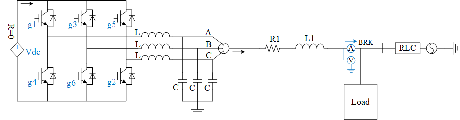
Figure 4. Main circuit topology diagram of inverter (Photo/Picture credit: Original).
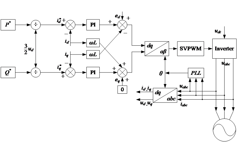
Figure 5. PQ Control Structure Diagram of MTGS (Photo/Picture credit: Original).
3. Modeling of PV-MT Hybrid Grid-Connected Power Generation System
3.1. Hybrid system framework
Fig. 6 displays the framework of the PV-MT hybrid power generation system. In this system, the PV power generation system and the micro-turbine generator system are connected to the grid via a common connection point (PCC). The PV system achieves maximum power point tracking through a DC converter, then connects to the AC bus via an inverter and filter circuit. The micro-turbine is connected to the AC bus after rectification and inversion, as analyzed before, allowing the combined operation of the photovoltaic and micro-turbine systems to supply power to the load. The PV system handles the base load of the micro-grid, and the MTGS can cover the remaining load and stay in a standby mode as a back-up source. The remaining question how is how to guarantee the two separate sources to operate in a hierarchical way.
As mentioned before, when the MTGS operates in grid-connected mode, a control strategy for active power (P) and reactive power (Q) is adopted to ensure system stability and efficient operation. The PQ control strategy focuses on how to adjust active and reactive power to meet the grid's demands and maintain system stability. To be more specific, the active power (P) control adjusts the output to match the grid's power demand or the system's preset power output target, while the reactive power (Q) control helps maintain voltage stability and optimize the power factor to meet the grid's voltage requirements. Therefore, in the PV-MT system, the coordination control should also concentrate on the PQ control on a higher level.
In essence, the P coordination control needs to adjust the output power of the micro-turbine generator system based on the load demand and the PV output, ensuring the smooth operation of the PV-MT system. The Q coordination control is necessary to compensate for any shortfall in reactive power when the photovoltaic system cannot supply all the required reactive power on its own, with the micro-turbine generator system providing the additional reactive power.
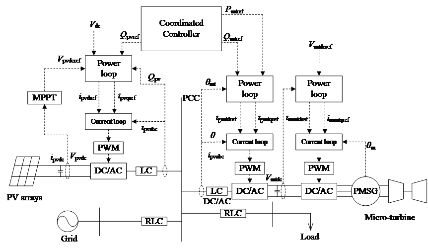
Figure 6. Coordinated control topology of PVMT generation system (Photo/Picture credit: Original).
3.2. PQ coordination control
Fig. 7 shows a PQ coordination control strategy for a PVMT power generation system, which includes active power coordination and voltage fluctuation suppression control. For the active power coordination part, the first step is to check whether the PV power Ppv meets the load demand Pload. If Ppv is greater than or equal to Pload , the system can meet the load demand utilizing only PV power, with no need for additional power, and the PV sub-system operates independently. On the other hand, if Ppv is less than Pload , the PV sub-system cannot fully meet the load demand, and the MT needs to be activated to supply the additional power needed. In this case, the MT provides the power difference, and the PVMT system operates in a coordinated manner. The additional power demand for MTGS P*mt can be written as
\( {{P_{mt}}^{*}}={P_{load}}-{P_{pv}} \) (9)
For the reactive power coordination control part, the system first detects the voltage deviation |ΔVpcc| (which refers to voltage fluctuations at the point of common coupling). If the voltage fluctuation exceeds a certain threshold ΔVthreshold, it indicates a significant voltage fluctuation that requires reactive power adjustment to suppress. The reference reactive power Q* is calculated based on the equation:
\( {Q^{*}}=K|Δ{V_{pcc}}| \) (10)
where K is a coefficient that determines the responsiveness of the reactive power adjustment. The system then checks if the calculated Q* is within the allowable maximum reactive power range (where Qpvmax and Qmtmax are the maximum reactive power outputs of the PV system and the micro-turbine, respectively). If Q* is less than the PV system's maximum reactive power Qpvmax, the PV system directly provides reactive power. If Q* exceeds Qpvmax but is within the combined maximum reactive power of the PV system and MT system, the PV system provides its maximum reactive power, and the MT supplies the remaining portion Q*mt as
\( {{Q_{mt}}^{*}}={Q^{*}}-{Q_{pvmax}} \) (11)
If Q* exceeds the total reactive power capacity of both the PV and MT system, then Qpvmax and Qmtmax togetherr provide the maximum reactive power the PVMT system can offer.
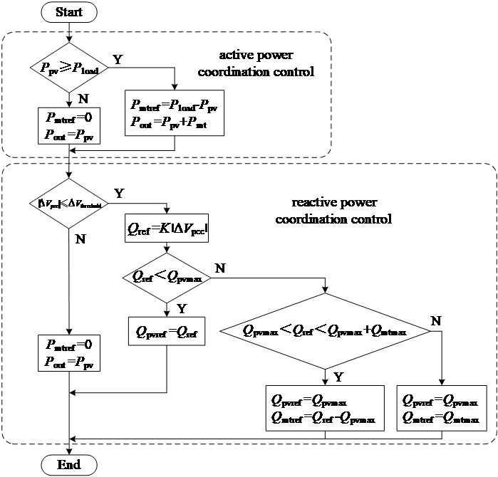
Figure 7. PQ coordination control block diagram of the hybrid PVMT system (Photo/Picture credit: Original).
4. Inertia enhancement analysis
The previous section explained the feasibility of the proposed PVMT strategy from a technical perspective. This section highlights the advantages of integrating MT into PV systems from the inertia perspective. In traditional power systems, inertia refers to the ability of rotating machinery, like generator rotors, to store kinetic energy. When there are frequency fluctuations in the grid (such as sudden increases or decreases in load), the system can temporarily stabilize the frequency by releasing or absorbing this kinetic energy. Fig. 8 shows the impact of system inertia on frequency change (Δf) and power change (ΔP). The red curve represents a system with high inertia, while the blue curve represents a system with low inertia. When a disturbance occurs, the system with higher inertia can better cushion the rapid changes in frequency, whereas the system with lower inertia experiences a faster and larger frequency drop, and its recovery is slower. Additionally, it can be seen that the presence of a generator helps to more effectively regulate power output, slowing the rate of power change and gradually bringing the power back to a balanced state. Inertia provides a short buffer time, allowing other control systems, like frequency regulation mechanisms, to respond and maintain overall system stability.
However, PV systems convert solar energy directly into electrical energy using semiconductor devices like PV cells, which do not involve rotating machinery. As a result, PV systems naturally lack the traditional mechanical inertia, making them slower to respond to grid frequency changes. This lack of inertia poses challenges to grid stability, especially when PV systems are integrated on a large scale. On the other hand, the turbine in the MT system is a rotating machine, providing a certain amount of mechanical inertia. When grid frequency fluctuations occur, the micro gas turbine can offer an immediate response through its rotational kinetic energy, helping to slow down the frequency changes. This mechanical inertia is a significant advantage compared to the "zero inertia" of PV systems.
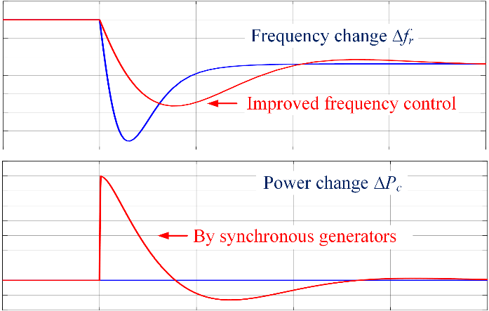
Figure 8. Effect of power system inertia (Photo/Picture credit: Original).
Fig. 9 shows the curve of frequency change Δfr over time t, reflecting the system's frequency response in scenarios with and without inertia simulation in the power system [13]. The black dashed line represents the frequency change when the system lacks inertia. When the system experiences a disturbance, such as a sudden increase in load or a decrease in generation, the frequency drops rapidly, showing a significant initial frequency deviation. Over time, the system gradually recovers its frequency through frequency regulation mechanisms, but without inertia support, the recovery time is longer, and the frequency fluctuations are larger. The green solid line represents the frequency change when the system includes inertia simulation. In this case, the additional kinetic energy provided by inertia significantly reduces the magnitude of the frequency drop, and the recovery time is shorter. The proposed PVMT system can offer a mechanical inertia response similar to that of traditional synchronous generators, and immediately respond to changes in grid frequency, providing short-term energy support, reducing the extent of frequency fluctuations, and thus improving frequency stability and shortening the recovery time.
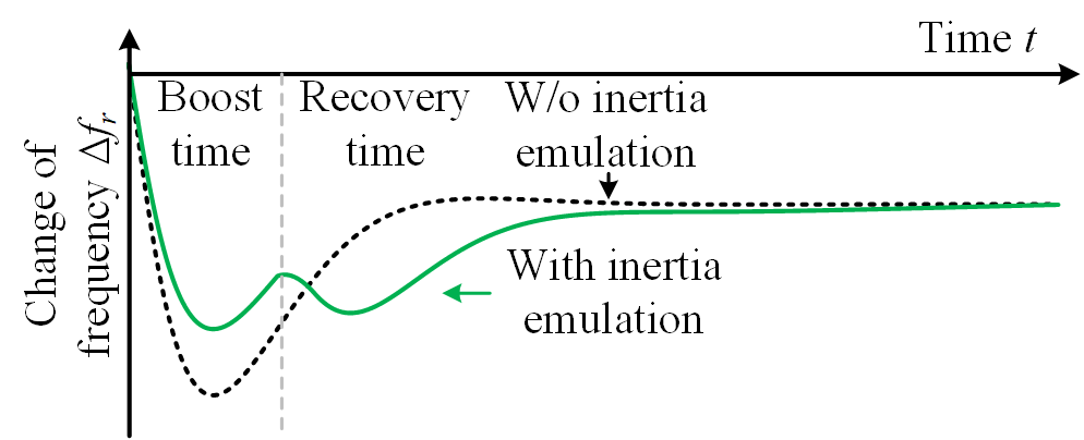
Figure 9. Effect of inertia enhancement [13].
5. Conclusion
To sum up, this study proposes a hybrid PVMT power generation system that integrates MT into PV generation systems. It models the MT and its control, proposes the PVMT framework, and analyzes the inertia benefits provided by the MT. Through coordinated control, the PVMT system can flexibly manage the output of both the PV system and MT, ensuring stable operation under different load conditions. Additionally, it can provide inertia support and actively participate in grid frequency regulation. Therefore, integrating MT as a backup power source for PV systems is technically feasible and valuable for scenarios requiring high reliability in power supply.
References
[1]. Aramendia E, Brockway P E, Taylor P G, et al. 2024 Estimation of useful-stage energy returns on investment for fossil fuels and implications for renewable energy systems. Nature Energy vol 11 pp 1-14.
[2]. Muhtadi A, Pandit D, Nguyen N, et al. 2021 Distributed energy resources based microgrid: Review of architecture, control, and reliability IEEE Transactions on Industry Applications vol 57(3) pp 2223-2235.
[3]. Sarvi M, Azadian A 2022 A comprehensive review and classified comparison of MPPT algorithms in PV systems Energy Systems vol 13(2) pp 281-320.
[4]. Liu B, Xing X, Liu C 2024 Simplified Double-vector Finite Control Set Model Predictive Control for LCL-filtered T-type Inverters with Active Damping 3rd Conference on Fully Actuated System Theory and Applications (FASTA) pp 1364-1369.
[5]. Zhu T, Wills R G A, Lot R, et al. 2021 Adaptive energy management of a battery-supercapacitor energy storage system for electric vehicles based on flexible perception and neural network fitting. Applied Energy vol 292 p 116932.
[6]. Fang J, Si W, Xing L, et al. 2023 Analysis and Improvement of Transient Voltage Stability for Grid-Forming Converters IEEE Transactions on Industrial Electronics vol 17.
[7]. Ayaz S K, Altuntas O, Caliskan H 2021 Enhanced life cycle modelling of a micro gas turbine fuelled with various fuels for sustainable electricity production Renewable and Sustainable Energy Reviews vol 149 p 111323.
[8]. Saib S, Gherbi A, Bayindir R, et al. 2020 Multi-objective optimization of a hybrid renewable energy system with a gas micro-turbine and a storage battery Arabian Journal for Science and Engineering vol 45(3) pp 1553-1566.
[9]. Khaburi D A, Nazempour A 2012 Design and simulation of a PWM rectifier connected to a PM generator of micro turbine unit Scientia Iranica vol 19(3) pp 820-828.
[10]. Roy K 2021 Optimal energy management of micro grid connected system: A hybrid approach. International Journal of Energy Research vol 45(9) pp 12758-12772
[11]. Banihabib R, Assadi M 2022 The role of micro gas turbines in energy transition Energies vol 15(21) p 8084.
[12]. Bohn D 2004 Micro Gas Turbine and Fuel Cell: A Hybrid Energy Conversion System with High Potential; von Kármán Institute: Rhode-StGenèse, Belgium, NATO Research & Technology Organisation, Report number RTO-EN-AVT-131.
[13]. Fang J, Li H, Tang Y, et al. 2018 On the inertia of future more-electronics power systems IEEE Journal of Emerging and Selected Topics in Power Electronics vol 7(4) pp 2130-2146.
Cite this article
Ye,A. (2024). Modeling and Analysis of Micro-Turbine Integrating PV Generation Systems. Applied and Computational Engineering,98,6-14.
Data availability
The datasets used and/or analyzed during the current study will be available from the authors upon reasonable request.
Disclaimer/Publisher's Note
The statements, opinions and data contained in all publications are solely those of the individual author(s) and contributor(s) and not of EWA Publishing and/or the editor(s). EWA Publishing and/or the editor(s) disclaim responsibility for any injury to people or property resulting from any ideas, methods, instructions or products referred to in the content.
About volume
Volume title: Proceedings of the 2nd International Conference on Functional Materials and Civil Engineering
© 2024 by the author(s). Licensee EWA Publishing, Oxford, UK. This article is an open access article distributed under the terms and
conditions of the Creative Commons Attribution (CC BY) license. Authors who
publish this series agree to the following terms:
1. Authors retain copyright and grant the series right of first publication with the work simultaneously licensed under a Creative Commons
Attribution License that allows others to share the work with an acknowledgment of the work's authorship and initial publication in this
series.
2. Authors are able to enter into separate, additional contractual arrangements for the non-exclusive distribution of the series's published
version of the work (e.g., post it to an institutional repository or publish it in a book), with an acknowledgment of its initial
publication in this series.
3. Authors are permitted and encouraged to post their work online (e.g., in institutional repositories or on their website) prior to and
during the submission process, as it can lead to productive exchanges, as well as earlier and greater citation of published work (See
Open access policy for details).
References
[1]. Aramendia E, Brockway P E, Taylor P G, et al. 2024 Estimation of useful-stage energy returns on investment for fossil fuels and implications for renewable energy systems. Nature Energy vol 11 pp 1-14.
[2]. Muhtadi A, Pandit D, Nguyen N, et al. 2021 Distributed energy resources based microgrid: Review of architecture, control, and reliability IEEE Transactions on Industry Applications vol 57(3) pp 2223-2235.
[3]. Sarvi M, Azadian A 2022 A comprehensive review and classified comparison of MPPT algorithms in PV systems Energy Systems vol 13(2) pp 281-320.
[4]. Liu B, Xing X, Liu C 2024 Simplified Double-vector Finite Control Set Model Predictive Control for LCL-filtered T-type Inverters with Active Damping 3rd Conference on Fully Actuated System Theory and Applications (FASTA) pp 1364-1369.
[5]. Zhu T, Wills R G A, Lot R, et al. 2021 Adaptive energy management of a battery-supercapacitor energy storage system for electric vehicles based on flexible perception and neural network fitting. Applied Energy vol 292 p 116932.
[6]. Fang J, Si W, Xing L, et al. 2023 Analysis and Improvement of Transient Voltage Stability for Grid-Forming Converters IEEE Transactions on Industrial Electronics vol 17.
[7]. Ayaz S K, Altuntas O, Caliskan H 2021 Enhanced life cycle modelling of a micro gas turbine fuelled with various fuels for sustainable electricity production Renewable and Sustainable Energy Reviews vol 149 p 111323.
[8]. Saib S, Gherbi A, Bayindir R, et al. 2020 Multi-objective optimization of a hybrid renewable energy system with a gas micro-turbine and a storage battery Arabian Journal for Science and Engineering vol 45(3) pp 1553-1566.
[9]. Khaburi D A, Nazempour A 2012 Design and simulation of a PWM rectifier connected to a PM generator of micro turbine unit Scientia Iranica vol 19(3) pp 820-828.
[10]. Roy K 2021 Optimal energy management of micro grid connected system: A hybrid approach. International Journal of Energy Research vol 45(9) pp 12758-12772
[11]. Banihabib R, Assadi M 2022 The role of micro gas turbines in energy transition Energies vol 15(21) p 8084.
[12]. Bohn D 2004 Micro Gas Turbine and Fuel Cell: A Hybrid Energy Conversion System with High Potential; von Kármán Institute: Rhode-StGenèse, Belgium, NATO Research & Technology Organisation, Report number RTO-EN-AVT-131.
[13]. Fang J, Li H, Tang Y, et al. 2018 On the inertia of future more-electronics power systems IEEE Journal of Emerging and Selected Topics in Power Electronics vol 7(4) pp 2130-2146.