


1. Introduction
The turbofan engine is one of the world's mainstream aviation engines, since the mid-1940s the first turbofan engine RB.80 Conway designed by R-R, after decades of development, turbofan engine has long been different, Boeing airliners using the CFM56 series engine [1], Pratt & Whitney JT3D engine and so on, are nowadays popular turbofan engine, but with the turbofan engine performance continues to improve, the operating temperature and pressure inside the engine for the engine material requirements are also getting higher and higher, overheating has been a problem in the study of turbofan engine. Engine performance continues to improve, the operating temperature and pressure within the engine for the engine material requirements are also increasingly high, overheating has been a problem in the study of turbofan engines. This paper study the working principle of turbofan engine, its application in civil aviation and military fields, as well as the high temperature and high-pressure environment inside the engine, and combine them with the literature to investigate the improvement of turbofan engine performance and the solution of overheating problem, hoping to make the engine performance higher and solve the overheating problem.
2. Concept and history of the turbofan engine
2.1. Concept
Turbofan engine, also known as ‘turbofan engine’, refers to the nozzle injection of gas and fan exhaust air together to produce reaction thrust gas turbine engine, by the pressurizer, combustion chamber, high-pressure turbine, low-pressure turbine and exhaust system (shown in Figure 1), which, together with the turbojet engine, turboprop engine, turboshaft engine form the four existing engines in the world. Compared with the other three engines, the turbofan engine increases the pre-turbine temperature without increasing the exhaust velocity, and the turbofan engine, through the design of the inner and outer culverts, makes the thermal efficiency and propulsion efficiency balanced, which greatly improves the efficiency of the engine, reduces the fuel consumption, and has a longer flight range.
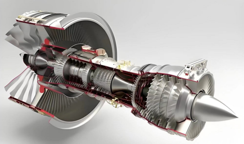
Figure 1. Turbofan Engine
2.2. History
In the 1950s and 1960s, the development of turbojet engine was relatively mature, Total pressurization ratio of the compressor of a turbojet engine reached about 14, maximum temperature before the turbine also reached 1000 ℃, but because people wanted to improve the engine thrust, and through the turbojet engine to add a fan to improve the windward area to increase the air flow, and thus turbofan engine gradually into the field of people's vision.
In the 1940s, the British company Rolls-Royce begun to put effort into the development of the ‘Conway’ turbofan engine, ‘Conway’ in 1953 for the first time on the ground test vehicle, after six years of fine-tuning. In March 1959, the ‘Conway MK-508’ was launched.[2]
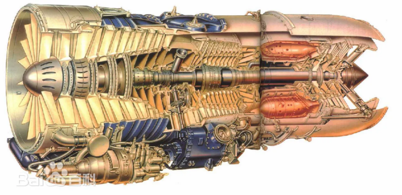
Figure 2. Conway MK-508 turbofan engine [2]
Later, although the United States for turbofan engine development is slightly slower than the United Kingdom, but the technical starting point is very high. The United States Pratt & Whitney play for turbojet engine is very full of technical reserves, the J57 and J91 nuclear power jet engine long blade combination, the new JT3D turbofan engine was born, it compared to the Conway engine, performance has been greatly improved. As the world's top three aviation power giants, the General Electric Company is also not willing to show weakness, developed the first generation of turbofan engine CJ805-23, which is the only turbofan engine using the rear fan design, RB211, PW4000, D-30KP-2, CFM56 and so on the engine is endless, the development of turbofan engines are still moving forward continuously.
3. Structure and working principle of turbofan engine components
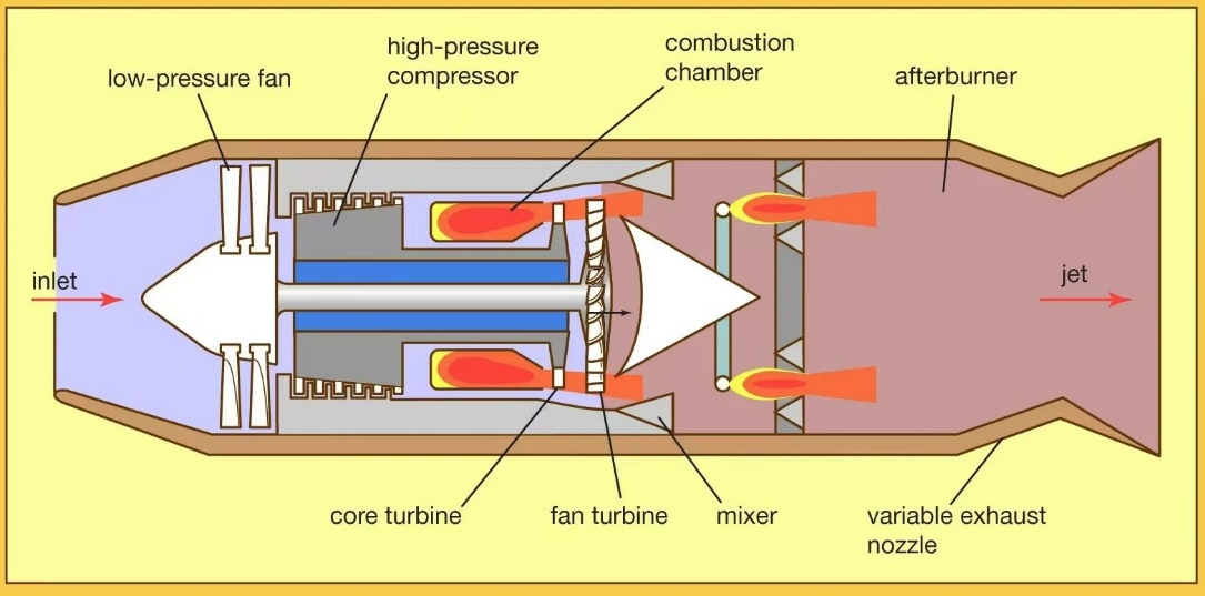
Figure 3. Typical small-content-ratio turbofan engine structure [3]
3.1. Intake duct
The inlet of the turbofan engine is situated at the front end of the engine and is a round or flat pipe. The outside air passed through the intake tract. Part of it flows into the compressor in the inner culvert, while the other part directly enters the other culvert. It does not pass through the compressor and the combustion chamber but directly sprays out from the tail nozzle. In addition, when the aircraft is flying at high speed, the intakes are also capable of decelerating and pressurizing the incoming air.
There are two types of intakes: subsonic intakes and supersonic intakes. Subsonic intakes have a blunt rounded leading edge to avoid airflow separation at the inlet during low-speed takeoff. Subsonic intakes are simple in structure and light in weight, and are widely used in low-supersonic aircrafts with Mach numbers below 1.6. The supersonic inlet has a sharp leading edge, and the deceleration of the supersonic airflow is achieved by a number of weaker oblique excitations. Supersonic intakes are classified into three types: external pressure, internal pressure, and hybrid.
3.2. Fan
The fan of the turbofan engine is transformed from the propeller of the turboprop engine by shortening the diameter of the propeller blades and increasing the number of blades, which is located at the front end of the engine. The fan pressurizes the incoming outside air and pushes the air into the engine through the inner and outer culverts. The air that passes through the outer culvert is ejected directly from the tail nozzle, creating a reverse force to propel the aircraft forward, so the fan also affects the amount of thrust of the aircraft to some extent.
3.3. Compressor
The compressor is located between the air intake and the combustion chamber, as the name suggests, its role is to compress the incoming air to increase the pressure, and then transfer to the combustion chamber. The structural form and airflow characteristics can be divided into three types of pressurized air, axial, centrifugal and hybrid. The axial compressor consists of several stages, each of which contains a row of rotor blades and a row of static blades. The rotor is linked to the turbine shaft, while the static is fixed to an external magazine, and both compress the incoming air and transfer the compressed air to the combustion chamber.
3.4. Combustion chamber
The combustion chamber is located after the compressor, the air compressed by the compressor enters into the combustion chamber, combines with the fuel in the combustion chamber and burns, the temperature rises, and produces high temperature and high-pressure gas to push the gas turbine to rotate. Then the combustion chamber pushes the high temperature and high-pressure gas to the turbine. Usually, the combustion chamber can be divided into annular combustion chamber, tube annular combustion chamber. Both have their own advantages and disadvantages. The volume, weight and oil circuit design of the annular combustion chamber are due to the tubular annular combustion chamber, while the structural strength of the tubular annular combustion chamber is superior to that of the annular combustion chamber. Today's turbofan engine will use the method of boost combustion to improve the performance of turbofan engine, compared with the same parameters of the traditional turbofan engine, in the total boost ratio of 25~45, the pre-turbine temperature of 1500~1800k, the boost combustion turbofan engine unit thrust increase of about 4.7%~8.6%, the fuel consumption rate is reduced by about 4.6%~8.5% [4].
3.5. Turbine
The turbine is positioned at the rear end of the combustion chamber. During the operation process of the turbofan engine, the turbine is mainly responsible for converting the enthalpy of the high-temperature and high-pressure gas exported from the combustion chamber into mechanical work[5]. Since the turbine is a hot end component, the turbine needs to work stably under high temperature and high-pressure environment, and needs to maintain high efficiency and a large working range. High-performance turbine has been a number of countries around the world has been doing research to improve the pre-turbine temperature is an effective way to increase the thrust of turbofan engines, but for the turbine materials are also faced with a big problem, high-performance high-temperature and high-pressure-resistant materials are also known as the object of research all the time.
3.6. Nozzle
The nozzle is located at the end of the engine, which belongs to the exhaust system of the engine. On the one hand, the nozzle will further expand the high-temperature gas at the end of the turbine and convert its chemical energy into kinetic energy, enabling the gas to be ejected at a higher speed. On the other hand, the nozzle will direct the air expelled by the fan into the outer culvert of the external air, resulting in a a reaction thrust and generating a larger thrust for the aircraft.
4. Application areas
4.1. Civil aircraft
Turbofan engine is currently the world's mainstream engine, which is widely used in civil passenger aircraft. Boeing's 737 series, China's C919, as well as Europe's AirBus320 and so on are all using turbofan engines. Turbofan engine performance compared to the nineties of the turboprop engine, performance is better, the fuel consumption rate is lower, and for the civil aviation airliner, noise is a more concerned about the problem, and turbofan engine low noise just to meet the needs of the civil aviation airliner. Nowadays, turbofan engine has become the mainstream civil airliner engine, and with the development of science and technology and materials, the performance is gradually improved.
4.2. Military aircraft
After World War II, Germany developed the first turbofan engine. However, due to various shortcomings, it failed to progress further. It was not until the 1960s, when a suitable fan blade for the turbofan engine was manufactured, that the turbofan engine entered the practical stage.In the 1970s, the United States first developed the F100-PW-100 home is a turbofan engine, and in November 1974, equipped with two F100-PW-100 engine F-15 into the U.S. Air Force and began service, since then, the turbofan engine is gradually applied to the military field, prompting the fighter into the ‘third-generation’ new stage. Since then, turbofan engines have been gradually used in the military field, prompting fighter jets to enter the ‘third generation’ stage. After that, countries around the world have developed a new generation of fighters, the U.S. F-16, F/A-18, Europe's ‘Rafale’, the Soviet Union's Mig-29, Su-27 and so on. Nowadays, the turbofan engine has been updated for decades and its performance has been greatly improved, and the F135 is regarded as the most powerful combat engine in history. It was developed by the U.S. Pratt & Whitney. By using advanced high-temperature alloys and ceramic matrix composites, its combustion efficiency and thrust output have been improved. The maximum thrust and the engine thrust-to-weight ratio are among the world's leading levels in combat engines.
5. Engine performance
5.1. Fan parameters
5.1.1. Fan efficiency. The fan of the turbofan engine is located at the front end of the engine, and the air entering from the outside world through the intake tract is transported through the internal and external culverts to the engine tail nozzle to produce thrust to propel the aircraft, so the fan efficiency has a very big impact on the performance of the aircraft engine. As the fan efficiency decreases, the work required to maintain the fan speed increases, so the low- pressure turbine needs to increase power to keep the fan speed stable. The low- pressure turbine can be achieved by increasing the pre-turbine inlet temperature, and gas flow rate into the turbine to increase the low- pressure turbine efficiency [6].
5.1.2. Fan flow. The effect of fan flow on engine performance is shown in Fig. Fan flow decreases, the air flow into the engine decreases, the work required for fan rotation decreases, the air flow into the combustion chamber to burn with the fuel decreases, the combustion chamber exit temperature T14 decreases, the low- pressure turbine n2 speed decreases, the engine culvert ratio increases, and the aircraft thrust decreases with the decrease in fan flow.
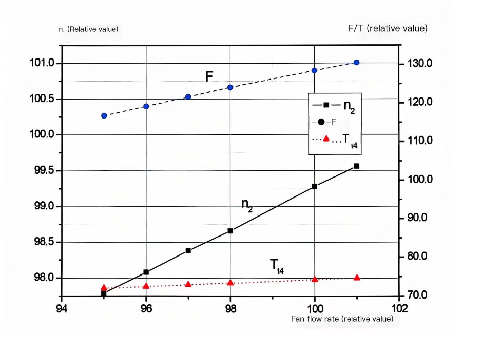
Figure 4. Effect of fan flow on engine performance [7].
5.2. Combustion chamber parameters
5.2.1. Combustion chamber efficiency. The combustion chamber is the core machine of the turbofan engine, located after the compressor and before the turbine. The combustion chamber converts the chemical energy of the fuel into heat energy to form a high temperature and pressure gas to drive the turbine to do work. As the efficiency of the combustion chamber decreases, the engine flow parameters and high and low- pressure rotor speeds are basically unchanged by increasing the fuel flow to maintain the combustion chamber outlet temperature as well as the rotor power balance. With the increase of fuel flow, the gas flow at the combustion chamber outlet increases, the engine thrust increases, and the fuel consumption rate decreases significantly.
5.2.2. Excess air ratio. Excess air coefficient is also known as ‘excess air coefficient’, ‘air excess coefficient’, commonly known as ‘excess air ratio’. Refers to the actual supply of fuel combustion air volume and the ratio of theoretical air volume. Usually, in the combustion chamber of an aero-air engine, the excess air ratio is an important data. According to many studies on engine performance and emission laws at different excess air ratios, it is concluded that when the excess air ratio is between 1.1 and 1.2, the specific air consumption of the engine is the smallest, the exhaust temperature is very low, and the emission economy and reliability of the engine are all very good in this range.
6. Engine overheating problem
Currently the most advanced aero-engine thrust to weight ratio of 12 ~ 15, turbine gas temperature before reaching 1800 ~ 2100 ℃, its turbine blade working environment is extremely harsh, need to withstand a great deal of work stress and high operating temperatures at the same time. Why does the aero-engine work will produce such a high temperature? This is related to the principle of engine operation. Air is sucked into the compressor for compression, the pressure increases significantly, and then the high-pressure air into the combustion chamber and the fuel is fully mixed with combustion, resulting in high temperature and high-pressure gas into the turbine. In the combustion chamber, the temperature is usually at 1800 ~ 2100 ℃, the higher the temperature, the combustion chamber fuel and high-pressure air mixing will be more fully, thus generating more thrust. High-temperature and high-pressure gas drives the turbine blades to rotate, the rotating turbine shaft and drive the compressor and fan operation, forming a cycle. Some data show that the turbine inlet temperature increases by 100 degrees, the engine thrust-to-weight ratio increases by 10 per cent. Aero-engine working environment is very harsh, the turbine blade not only to withstand thousands of degrees of high temperature burning, but also to withstand the huge working stress.
6.1. High temperature resistant materials
6.1.1. Ceramic matrix composite. Ceramic-Matrix Composite (CMC) inherits the advantages of ceramic materials such as high temperature resistance and corrosion resistance, overcomes the brittleness of ceramic materials, has lower density compared to high temperature alloys, better high temperature endurance strength, and stronger designability, and is an ideal material for the thermal structure of new generation of aero-engine [8]. At present, scientists have found many ways of toughening through various studies, the most effective of which is continuous fiber toughening in reinforcement toughening, which makes ceramic matrix composites known as a new type of high-temperature-resistant, low-density structural material. At present, the world's most mature application is silicon carbide ceramic matrix composites (CMC-SiC), only the United States, Germany, France and Japan in the vigorous development of the CMC-SiC industry and its application in the core of the aircraft engine part of the machine. The application of CMC-SiC in the combustion chamber can significantly increase the operating temperature of the combustion chamber and reduce the structural mass [9]; the application of CMC-SiC in the turbine part of the engine can improve the corrosion and wear resistance, and improve the working life of the parts.
6.2. Thermal barrier coating
Thermal barrier coating, as the name suggests, is a layer of heat barrier on the surface of the parts, which is deposited on the surface of high temperature resistant metals or alloys, to play the role of heat insulation, reduce the temperature of the parts and improve thermal efficiency. Currently in the aerospace field, the temperature of the hot end parts is getting higher and higher, especially the combustion chamber and turbine blades, the working temperature has reached the limit of high temperature metals and alloys, then the use of thermal barrier coatings will be able to solve this problem.
There are three preparation methods for thermal barrier coatings, plasma spraying, electron beam-physical vapor deposition and plasma spraying-physical vapor deposition, with the first two methods being the main preparation techniques. Take turbine blades as an example, the thermal barrier coating has become like the 'protective clothing' for modern turbine blades. It not only can enhance the corrosion resistance of the turbine blades, further increase the operating temperature of the engine, but also can reduce fuel consumption (estimated to be approximately 20%) and extend the service life of the hot end components.
However, due to the extremely harsh working environment of the engine hot end components, the thermal barrier coating will also be oxidized and corroded during high frequency thermal cycling operation, resulting in coating spalling and failure. Therefore, in order to ensure the reliability of the thermal barrier coating, people can determine the working condition of the thermal barrier coating through real-time monitoring and borehole inspection [10], so as to formulate a corresponding maintenance scheme to extend its service life.
7. Conclusion
Based on the development history and working principle of the turbofan engine, this paper explores how to enhance the engine performance by altering the fan efficiency, fan flow rate, and combustion chamber efficiency of the aero-engine. It adopts advanced high-temperature resistant ceramic-based composite materials as the materials for some engine parts and employs the method of spraying thermal barrier coating on the parts to assist the engine in resisting the high-temperature environment during operation, thereby achieving a deeper understanding and research on the turbofan engine. The turbofan engine has a more in-depth understanding and research. In this paper, there are still some shortcomings in the study of thermal barrier coating, although the thermal barrier coating can help parts resist the high temperature of the working environment, but if the working time is too long, the thermal barrier coating will fail and oxidize at high temperatures, so there is still a need for more in-depth research on the thermal barrier coating, and improve and optimize the coating, so that it can work more durably. In the future, there will be better high-temperature-resistant materials to help turbofan engines to improve performance and operating cycle.
Acknowledgement
I am very grateful to my teachers for their hard work in the classroom to teach us about aircraft design, fluid dynamics and other aspects of knowledge, different types of aero-engine structure and performance parameters, and after the class to be able to patiently answer some of my questions, in the course of these courses I have accumulated a lot of knowledge about aircraft and aero-engine, which is very helpful for my professional learning. This helped me a lot in my study of professional courses, and I won the second prize of the People's Scholarship in the 23-24 academic year, which also laid a solid foundation for the creation of my dissertation, and I am very grateful to the teachers of my various courses.
References
[1]. Sun Guiqing,Zhao Zhe,Sun Huijie & Li Zelin. (2020).Analysis of rotor balancing process for high pressure compressor rotor of CFM56 engine. Aeroengine (06), 92-97. doi:10.13477/j.cnki.aeroengine.2020.06.015.
[2]. Dongfang.com, Turbofan engine; US JT3D becomes milestone in aviation development history, 2011-09-07, https://www.ckhq.net/arc/jwjs/zzls/2011/0907/29768.html
[3]. Shuangqi An. (2018). An overview of the working principle and application of turbofan engine. Internal Combustion Engines and Accessories (01), 68-70. doi:10.19475/j.cnki.issn1674-957x.2018.01.032.
[4]. Wang, Xiaodong Wang, Changsheng Rui & Yanjun Zhang. (2023). Thermal process and performance analysis of turbofan engine with pressurised combustion in main combustion chamber. Aeroengine (02), 28-36. doi:10.13477/j.cnki.aeroengine.2023.02.004.
[5]. Chen JJ. (2018). A review of the working principle and application of turbofan engine. Times Automotive (05),115-116.
[6]. He Minxiang, Deng Shaochun, Wang Deqing, Wen Qiang, Song Ruimin & Zhu Aidi. (2022). Study on the effect of component characteristic change on the performance of a turbofan engine. Engineering and Testing(02),49-51+124.
[7]. He Min-Xiang, Deng Shao-Chun, Wang De-Qing, Wen Qiang, Song Rui-Min & Zhu Ai-Di. (2022). Study on the effect of component characteristic change on the performance of a turbofan engine. Engineering and Testing(02),49-51+124.
[8]. Li Longbiao. Progress of ceramic matrix composites in aero-engine application and airworthiness compliance verification. Journal of Composite Materials 1-34. doi:10.13801/j.cnki.fhclxb.20240623.002.
[9]. Li Longbiao. Research progress of ceramic matrix composites in aero-engine application and airworthiness compliance verification. Journal of Composite Materials 1-34. doi:10.13801/j.cnki.fhclxb.20240623.002.
[10]. Yuan, Z. D. & Wang, D. W.. (2024). Application, Failure and Maintenance of Thermal Barrier Coatings on Aero-engine Turbine Blades. Shanghai Coatings (02), 49-53.
Cite this article
Xu,Z. (2024). Study of Turbofan Engine Components and Performance with Overheating Problems. Applied and Computational Engineering,114,178-185.
Data availability
The datasets used and/or analyzed during the current study will be available from the authors upon reasonable request.
Disclaimer/Publisher's Note
The statements, opinions and data contained in all publications are solely those of the individual author(s) and contributor(s) and not of EWA Publishing and/or the editor(s). EWA Publishing and/or the editor(s) disclaim responsibility for any injury to people or property resulting from any ideas, methods, instructions or products referred to in the content.
About volume
Volume title: Proceedings of the 2nd International Conference on Machine Learning and Automation
© 2024 by the author(s). Licensee EWA Publishing, Oxford, UK. This article is an open access article distributed under the terms and
conditions of the Creative Commons Attribution (CC BY) license. Authors who
publish this series agree to the following terms:
1. Authors retain copyright and grant the series right of first publication with the work simultaneously licensed under a Creative Commons
Attribution License that allows others to share the work with an acknowledgment of the work's authorship and initial publication in this
series.
2. Authors are able to enter into separate, additional contractual arrangements for the non-exclusive distribution of the series's published
version of the work (e.g., post it to an institutional repository or publish it in a book), with an acknowledgment of its initial
publication in this series.
3. Authors are permitted and encouraged to post their work online (e.g., in institutional repositories or on their website) prior to and
during the submission process, as it can lead to productive exchanges, as well as earlier and greater citation of published work (See
Open access policy for details).
References
[1]. Sun Guiqing,Zhao Zhe,Sun Huijie & Li Zelin. (2020).Analysis of rotor balancing process for high pressure compressor rotor of CFM56 engine. Aeroengine (06), 92-97. doi:10.13477/j.cnki.aeroengine.2020.06.015.
[2]. Dongfang.com, Turbofan engine; US JT3D becomes milestone in aviation development history, 2011-09-07, https://www.ckhq.net/arc/jwjs/zzls/2011/0907/29768.html
[3]. Shuangqi An. (2018). An overview of the working principle and application of turbofan engine. Internal Combustion Engines and Accessories (01), 68-70. doi:10.19475/j.cnki.issn1674-957x.2018.01.032.
[4]. Wang, Xiaodong Wang, Changsheng Rui & Yanjun Zhang. (2023). Thermal process and performance analysis of turbofan engine with pressurised combustion in main combustion chamber. Aeroengine (02), 28-36. doi:10.13477/j.cnki.aeroengine.2023.02.004.
[5]. Chen JJ. (2018). A review of the working principle and application of turbofan engine. Times Automotive (05),115-116.
[6]. He Minxiang, Deng Shaochun, Wang Deqing, Wen Qiang, Song Ruimin & Zhu Aidi. (2022). Study on the effect of component characteristic change on the performance of a turbofan engine. Engineering and Testing(02),49-51+124.
[7]. He Min-Xiang, Deng Shao-Chun, Wang De-Qing, Wen Qiang, Song Rui-Min & Zhu Ai-Di. (2022). Study on the effect of component characteristic change on the performance of a turbofan engine. Engineering and Testing(02),49-51+124.
[8]. Li Longbiao. Progress of ceramic matrix composites in aero-engine application and airworthiness compliance verification. Journal of Composite Materials 1-34. doi:10.13801/j.cnki.fhclxb.20240623.002.
[9]. Li Longbiao. Research progress of ceramic matrix composites in aero-engine application and airworthiness compliance verification. Journal of Composite Materials 1-34. doi:10.13801/j.cnki.fhclxb.20240623.002.
[10]. Yuan, Z. D. & Wang, D. W.. (2024). Application, Failure and Maintenance of Thermal Barrier Coatings on Aero-engine Turbine Blades. Shanghai Coatings (02), 49-53.