


1. Introduction
With the widespread application of robotic arms in the fields of industry, medical treatment, service robots, etc., how to improve the control accuracy and motion flexibility of robotic arms has become an important research topic. The efficient and precise control of multi-degree-of-freedom robotic arms depends on advanced algorithms and hardware technologies. Especially in complex dynamic environments, how to ensure that the robotic arms can accurately perform grasping tasks has become a technical challenge that needs to be solved in the field of automation[1]. At present, the motion control of robotic arms mainly relies on inverse kinematics algorithms, PID control, and spatial solution technologies. However, in practical applications, traditional control methods still have limitations in dealing with the position deviation and motion accuracy of target objects[2].
This paper proposes an innovative robotic arm motion optimization method, the "somersault" method, which overcomes the accuracy problem caused by large-angle rotation in traditional methods by decomposing the rotation action of the robotic arm chassis into multiple small-angle continuous rotations. Unlike the traditional single large-angle rotation, the "somersault" method enables the robotic arm to achieve more precise control in the entire workspace through small-angle decomposition, especially in the grasping of target objects in the negative semi-axis area, which significantly improves the grasping stability and positioning accuracy of the robotic arm[1].
In addition, this paper also optimizes the image recognition, inverse kinematics, and PID control algorithms of the robot arm, and realizes real-time image processing and motion control through FPGA hardware acceleration[3]. Through the combination of these technologies, the system designed in this paper shows good accuracy and stability in multi-target grasping and dynamic environments, providing a new solution for the future application of robot arms in the fields of industrial automation and service robots.
2. System overview
The system is based on the FPGA development kit. It processes and analyzes the image of the target object, calculates the position and posture of the object, and then uses inverse kinematics and spatial solution to control the robotic arm to complete the specified action. The system mainly includes modules such as image acquisition, image processing, robotic arm control and host computer communication. In terms of hardware, the system uses an FPGA development board and a servo controller. The image acquisition module uses a camera sensor and realizes image display through a VGA interface. A variety of algorithms are used in the design, including the PID control algorithm for robotic arm position calibration and the CORDIC algorithm for trigonometric function calculation. All functional modules are implemented on the FPGA to ensure the real-time and reliability of the system[3].
3. System architecture analysis
3.1. System composition
The system is mainly composed of image acquisition, image processing, data processing algorithm (CORDIC), robotic arm control algorithm, image display and other additional functions such as host computer[4].
3.2. Functional module introduction
The system designed in this paper is used to control the precise movement of the robot arm through image processing technology. The system architecture mainly includes the following modules: First, the image acquisition module is responsible for the register configuration of the camera and reads the image data collected by the camera in real-time to provide basic information for subsequent processing[5]. Secondly, the image processing module pre-processes the collected image and distinguishes the thin sheet according to the color and shape of the image to identify the characteristic information of the target object. Then, the control module solves the three-dimensional coordinates of the robot arm through the image coordinate information, calculates the preset angle of the servo, and then controls the movement of the robot arm according to the calculation results. In order to improve the user-friendliness and accuracy of the system, the system also designs additional functional modules, including an image display module, host computer interface and angle calibration. The image display module outputs image information intuitively by reading the image data in the cache and driving the VGA display; the host computer interface displays the status information of the system in real-time, which is convenient for the operator to monitor and adjust; the angle calibration module ensures the accuracy of the robot arm by maintaining or automatically correcting the servo angle[6][7]. The system's modular design improves its stability and flexibility, which helps achieve high-precision robot arm control.
4. Theory and methods
Inverse kinematics is the core task of manipulator control, which is used to calculate the joint angle according to the target position. However, the traditional solution method consumes a lot of computing resources in FPGA implementation, especially floating-point operations. This design uses a spatial solution iterative algorithm to gradually approach the target angle to reduce resource consumption and improve real-time performance[7].
In order to achieve precise control of the manipulator, this paper adopts a step-by-step simplification and optimization scheme. First, the model simplification part uses the Denavit-Hartenberg (DH) parameter method to represent the joint position of the manipulator and simplifies it into a three-axis model. Only the angles of the upper arm and the lower arm need to be calculated, which significantly reduces the computational complexity. Then, in the initial angle estimation, the initial angle of the end position of the manipulator is estimated through the preliminary information of the target position as a reference value for an iterative solution. In the iterative approximation stage, the error is calculated and the angle is corrected for each iteration until the error is less than the set threshold. This process uses the CORDIC algorithm to calculate the trigonometric function value, which is implemented by shifting, addition, and subtraction without floating-point operations. Finally, the result storage and reading module stores the final angle solution result in the ROM of the FPGA, and the state machine controls the process of each iteration to ensure efficient solutions in complex environments.
4.1. DH parameters
A robot can be made up of a series of joints and links. The joints can be sliding or rotating, and their order and plane can be arranged arbitrarily. The length and shape of the links are also flexible. Therefore, any set of joints and links can constitute a robot. When describing a robotic arm, the joints are usually rotating. To model a robot, people first need to specify a reference coordinate system for each joint, and then describe the coordinate transformation steps from one joint to the next. By combining all these transformations from the base to the end effector, you can get the total transformation matrix of the robot[8]. The DH model reduces two degrees of freedom by restricting the origin position and the direction of the X-axis, so only four parameters are needed to describe the original six-degree-of-freedom joint coordinate transformation,as shown in figure 1.
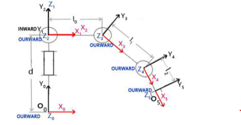
Figure 1: Polar coordinate system of the robotic arm
Formula conversion of robot arm coordinates and parameters:
\( {_i^i-1}T=[\begin{matrix}\begin{matrix}\begin{matrix}cos{θ_{i}} \\ cos{a_{i-1}}sin{θ_{i}} \\ \begin{matrix}sin{a_{i-1}}sin{θ_{i}} \\ 0 \\ \end{matrix} \\ \end{matrix} & \begin{matrix}-sin{θ_{i}} \\ cos{a_{i-1}}cos{θ_{i}} \\ \begin{matrix}sin{a_{i-1}}cos{θ_{i}} \\ 0 \\ \end{matrix} \\ \end{matrix} \\ \end{matrix} & \begin{matrix}\begin{matrix}0 \\ -sin{a_{i-1}} \\ \begin{matrix}cos{a_{i-1}} \\ 0 \\ \end{matrix} \\ \end{matrix} & \begin{matrix}{a_{i-1}} \\ -{d_{i}}sin{a_{i-1}} \\ \begin{matrix}{d_{i}}cos{a_{i-1}} \\ 1 \\ \end{matrix} \\ \end{matrix} \\ \end{matrix} \\ \end{matrix}]\ \ \ (1) \)
Key code implementation
// Simplified example code for angle correction
while (error > threshold) {
currentAngle = CORDIC_Calculate(currentX, currentY); // CORDIC calculate
error = calculateError(currentAngle, targetAngle);
adjustAngle(); // Correct the angle according to the error
}
4.2. Spatial solution iterative algorithm
4.2.1. Simplified robotic arm structure
According to the principle of inverse kinematics, we simplified the structure of the robot arm and used a three-axis robot arm to increase stability. The improvement is shown in Figure 2 below. The original θ1, θ2, and θ3 are changed to only θ1 and θ2.
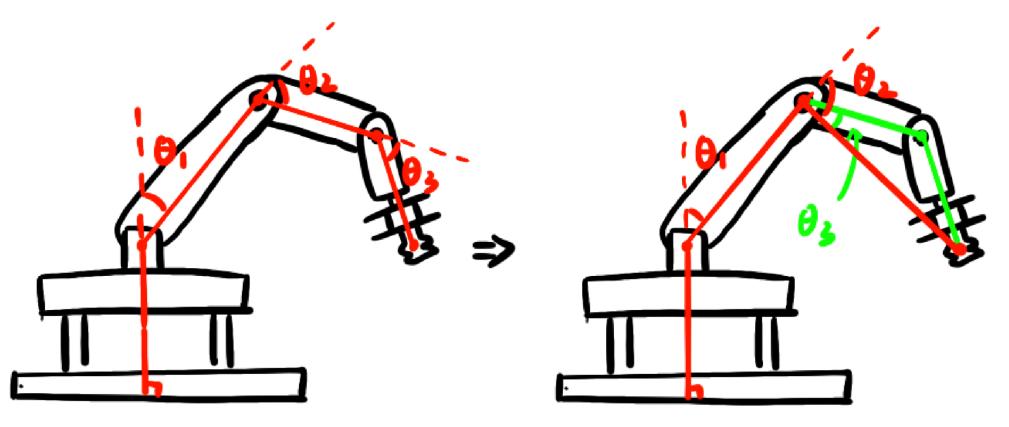
Figure 2: Simplified schematic diagram of the structure
If a traditional 4-axis robot is used, not only will the amount of calculation be large and the internal resources occupied, but it may also cause the overall shaking of the robot arm, greatly reducing the accuracy of the grasping[9]. When a 3-axis robot grasps an object, it only needs to adjust the arm axis and let the robot arm fall freely, which can reduce the complexity of the system and improve the accuracy of the grasping. According to the above inverse kinematics principle, the angle formula of the improved 3-axis robot arm can be calculated:
In space, the calculation formula of the extension distance L of the robot arm and the base axis θ0 is:
\( L={x^{2}}+{y^{2}}\ \ \ (2) \)
\( {θ_{0}}=atan{(\frac{y}{x})}\ \ \ (3) \)
Here, x and y are the horizontal and vertical coordinates of a point in space.
Convert the robot arm from a three-dimensional concept to a two-dimensional concept and calculate the formula for the upper arm angle and the lower arm angle:
\( L={l_{1}}sin{({θ_{1}})}+{l_{2}}sin{({θ_{1}}+{θ_{2}})}\ \ \ (4) \)
\( z={l_{0}}+{l_{1}}cos{({θ_{1}})}+{l_{2}}cos{({θ_{1}}+{θ_{2}})}\ \ \ (5) \)
By simplifying the equation, we can get the various values of the robot arm angles.
4.2.2. Iterative thinking of spatial solution
Utilizing the aforementioned technique to compute the angle of the robotic arm will need a substantial quantity of multipliers and logic units within the FPGA[9]. To conserve resources, akin to the CORDIC algorithm, the time-for-space method is employed to iteratively refine the angle value of the robotic arm, progressively converging on the most accurate value.
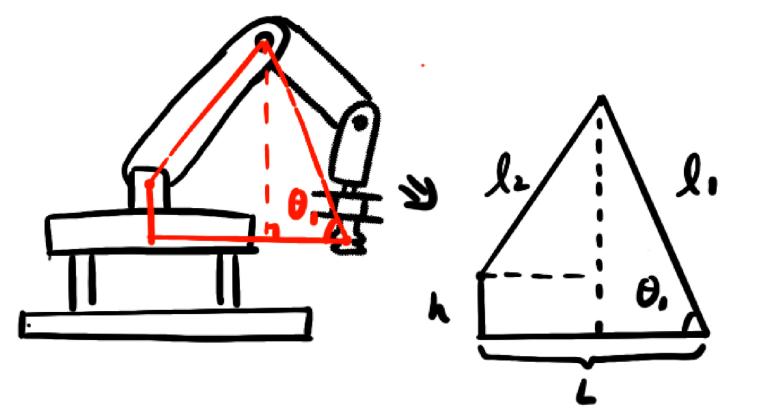
Figure 3: Schematic diagram of spatial solution
According to Figure 3 above, for given x, y, and z, the extension distance L of the robot arm and the rotation angle θ0 of the chassis can be calculated, which is the same as the inverse kinematics of the robot arm.
\( L={x^{2}}+{y^{2}}\ \ \ (6) \)
\( {θ_{0}}=atan{(\frac{y}{x})}\ \ \ (7) \)
The angle of the robot arm to the ground is denoted by a θ2, which we provide. From this angle, we can determine the height H of the robotic arm and the horizontal projection length x2 of the arm onto the ground:
\( H={l_{1}}cos{θ_{2}}\ \ \ (8) \)
\( {x_{2}}={l_{1}}sin{θ_{2}}\ \ \ (9) \)
The length of l2 may then be calculated by taking its square root.
\( {l_{2}}=\sqrt[]{{(L-{x_{2}})^{2}}+{(h-z)^{2}}} (10) \)
After obtaining l2, we compare the value of l2 with the actual length of the boom. If it is greater than the actual length, we need to increase the angle θ2 to move the upper end of the forearm away from the base, which is equivalent to increasing l2[8]. Conversely, reducing the angle θ2 will reduce l2 until l2 approaches the actual length of the boom. Finally, based on the iteratively obtained x2, calculate the boom angle θ1:
\( {θ_{1}}=arctan{(\frac{L-{x_{2}}}{H-h})}\ \ \ (11) \)
Spatial solving iterative algorithm - FPGA implementation
To conserve FPGA logic resources, the iteration angle is stored in ROM and accessed via its address. Concurrently, a state machine governs the execution of each calculation step, while reused modules (such as multipliers, dividers, and CORDIC calculation units) are employed to minimize resource wastage. The subsequent diagram illustrates the iterative approach for our spatial solution, in figure 4.:
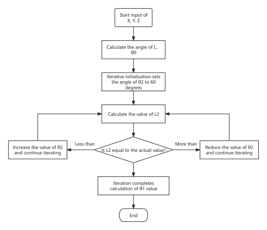
Figure 4: Flowchart of spatial solution algorithm
The iterated value is stored in ROM. After each iteration, the address needs to be incremented to get the next iteration[9].
4.3. CORDIC algorithm design
CORDIC algorithm is the abbreviation of coordinate rotation digital calculation. It was originally used for the coordinate transformation of trigonometric functions. After some promotion, it can also be used to calculate linear functions and hyperbolic functions (square root). The CORDIC algorithm only performs shift operations and addition and subtraction operations, so it is very suitable for use in hardware.
The algorithm consists of two parts: the circular system and the hyperbolic system. Here we mainly discuss the circular system, which has two modes: rotation mode and vector mode.
4.3.1. CORDIC algorithm - FPGA implementation
A substantial quantity of inverse tangent, square root, sine, and cosine computations is necessary for the calculation of the robot arm's position. To achieve robot arm posture computation with minimal resources, we integrated the circular and vector modes of the CORDIC algorithm into a single module, developed in a non-pipelined manner.
The module algorithm flow is shown in Figure 5:
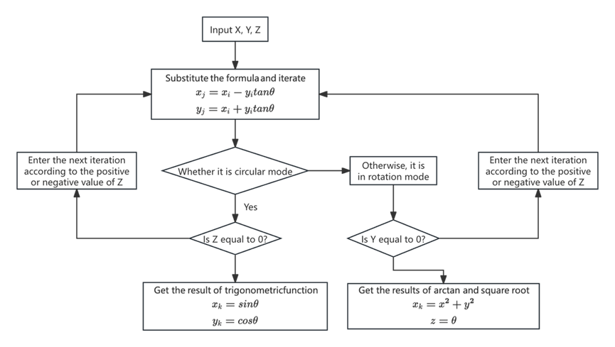
Figure 5: CORDIC algorithm flow chart
In the iterative process, the value of tanθ is difficult to determine, so the iterative angle is advanced from 45, 25.5... to 45, 26.565, 14.036... Through this transformation, the value of tanθ decreases by 2-i, which can be solved by simple shift operations in Verilog, greatly reducing the complexity of the system.
4.4. “The "somersault" method
In practical applications, the chassis of the robot arm usually moves within a semicircle. When the target is located on the negative semi-axis, a single large-angle rotation often causes motion instability and large positioning errors, affecting the grasping accuracy[10]. This design proposes a "somersault" method, which ensures the flexibility and stability of the chassis by decomposing a large-angle rotation into multiple small-angle rotations.
4.4.1. Angle decomposition and path planning
First, determine the required rotation angle of the chassis according to the position of the target object. If the angle is large (for example, more than 180°), decompose it into several small-angle rotations, usually between 20° and 30°, to ensure that the displacement changes brought by each rotation are smooth and reduce the impact of the accumulated rotation error. Ensure the order and direction of each small-angle rotation through path planning[10]. Taking the target object on the negative half axis as an example, when using the "somersault" method: the chassis first performs multiple small-angle rotations to allow the robot arm to gradually approach the negative half axis target. When approaching the target position, the end of the robot arm is gradually adjusted to the specified position to ensure accurate grasping.
4.4.2. Small angle control and PID regulation
During each small-angle rotation, PID control is applied to further reduce error accumulation:
Proportional control (P): Adjust the rotation speed according to the current error so that the robot arm gradually approaches the target angle.
Integral control (I): Eliminate the long-term accumulated errors in the system to ensure the position accuracy of the robot arm after the rotation is completed.
Differential control (D): Adjust the rotation speed at the beginning and end of the rotation to avoid instability caused by sudden speed changes. PID adjustment ensures the smoothness and accuracy of each small-angle rotation, allowing the robot arm to successfully complete the full path control.
When the robot arm approaches the target in the negative semi-axis area, the "somersault" method can keep the robot arm in a stable rotation range without having to rotate at a large angle at one time, thereby improving the positioning accuracy and grasping effect. This method is particularly suitable for the robot arm to efficiently complete the grasping task of the negative semi-axis target when the chassis rotation range is limited[10].
4.4.3. PID algorithm classification
In actual programming applications, it is necessary to use a discrete PID algorithm to adapt to the computer's usage environment. PID algorithms are generally divided into two types: positional and incremental algorithms. This design uses the positional PID algorithm. The following takes motor speed control (speed loop) as an example to explain the principle of the positional PID algorithm.
The position PID algorithm performs PID control based on the deviation between the actual position of the current system and the expected position to be achieved. The parameter definitions are shown in Table 1 below, and the algorithm flow is shown in Figure 6 .
Table 1: PID control parameter definition
PID parameters | Variable name | Detailed explanation |
Proportion P | e(k) | Current error |
Integral I | ∑e(i) | Accumulation of errors |
Differential D | e(k) - e(k-1) | This error - last error |
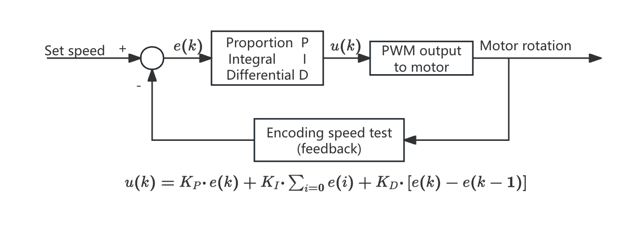
Figure 6: Position PID algorithm flow
4.4.4. PID algorithm - FPGA implementation
In the code, in order to calibrate the angle of the robot arm, the serial port module needs to be used to send and read the read and write instructions of the robot arm. Therefore, the state machine is used to control the serial port module to send and receive different instructions to achieve the control and calibration of the robot arm. The Figure 7 is the module block diagram of the module:
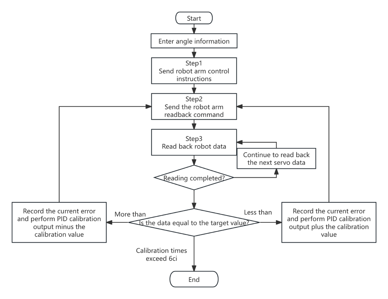
Figure 7: PID algorithm flow chart
During the PID parameter modification procedure, to enhance system stability and optimize FPGA resource use, we selected the proportionate integral value as 0.25. This process can be achieved by shifting to minimize the utilization of multiplier resources[11].
4.4.5. Method advantages
The "somersault" method avoids the error problem caused by large-angle rotation by decomposing it, allowing the robot arm to complete the task with high precision and high flexibility when grasping in the negative semi-axis area,in figure 8. Compared with traditional methods, its movement is more stable and significantly improves the grasping efficiency in complex environments.
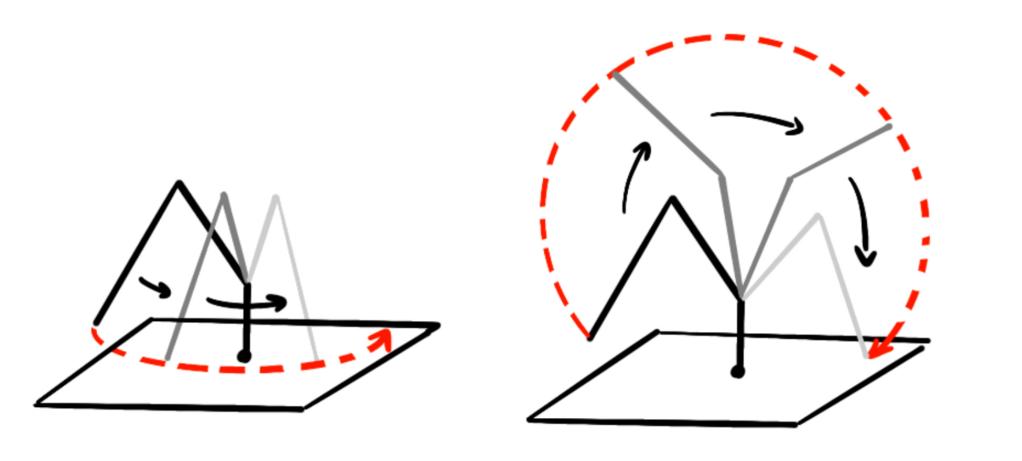
Figure 8: Schematic diagram of robot arm motion optimization
5. System performance analysis
Through experimental verification, the target locking time of the system is about 51.2ms, and it can complete the task of grasping and placing 12 objects within 1 minute and 30 seconds. The experiment shows that the average grasping position offset of the system is within 3mm, with high positioning accuracy. In addition, by adjusting the speed setting of the robot arm, the system optimizes the operation speed while ensuring accuracy, so that the robot arm can quickly complete the specified task.
The system also conducts a detailed performance evaluation in terms of hardware resource utilization and computing efficiency[11]. The logic resource utilization rate of the FPGA is controlled within 80%, and the hardware implementation of the CORDIC algorithm effectively reduces the demand for multipliers and other complex computing units. In the process of PID control implementation, the application of fixed-point number operations reduces the hardware complexity and improves the real-time performance of the control. In the dynamic response test of the robot arm, the system shows good anti-interference ability, and the robot arm can quickly return to the predetermined trajectory when disturbed by the outside world.
6. Conclusion
This design demonstrates the potential of FPGA-based precise control systems for robotic arms in industrial automation. Through reasonable algorithm selection and hardware resource optimization, the system achieves precise control of multi-DOF robotic arms. Image processing and control algorithms used in the design process, such as median filtering, color gamut conversion, inverse kinematics, spatial solution, and PID control, all support the efficient operation of the system. The hardware implementation ensures the real-time and accuracy of the system through the close integration of FPGA and servo. The system provides a useful reference for future research and development in the fields of industrial automation, robotic control, etc., and has the potential for further optimization and commercial application.
References
[1]. Yang, J. (2019). Digital image processing and MATLAB implementation (3rd ed.). Electronic Industry Press.
[2]. Liu, X., Xie, Y., Chen, H., et al. (2015). Optimization and implementation of CORDIC algorithm. Journal of Beijing Institute of Technology, 35(11), 1164-1170.
[3]. Ren, Z., Zhang, W., Li, Z., et al. (2024). Design of visual processing system based on FPGA. Manufacturing Automation, 46(03), 186-189.
[4]. Ma, Y., Zeng, T., & Jiang, H. (2023). Kinematic analysis and trajectory planning of robotic arm based on MATLAB. Packaging Engineering, 44(03), 187-193.
[5]. Zhang, H., Yu, L., & Sun, T. (2024). Research on mechanical design method of industrial robot arm joint.
[6]. Tao, Y., Liu, H., Wang, T., et al. (2021). Research progress and industrialization development trend of Chinese service robot. Journal of Mechanical Engineering, 58(18), 56-74.
[7]. Kung, Y. S., & Shu, G. S. (2005). Development of a FPGA-based motion control IC for robot arm. In Proceedings of the 2005 IEEE International Conference.
[8]. Meshram, U., Bande, P., Dwaramwar, P. A., et al. (2009). Robot arm controller using FPGA. In Proceedings of the 2009 International Multimedia, Signal Processing and Communication Technologies (pp. 8-11).
[9]. Meshram, U. D., & Harkare, R. (2010). FPGA based five axis robot arm controller. International Journal of Electronics Engineering, 2(1), 209-211.
[10]. Linares-Barranco, A., Perez-Peña, F., Jimenez-Fernandez, A., et al. (2020). ED-BioRob: A neuromorphic robotic arm with FPGA-based infrastructure for bio-inspired spiking motor controllers. Frontiers in Neurorobotics, 14.
[11]. Afaq, A., Ahmed, M., Kamal, A., et al. (2015). Development of FPGA-based system for control of an unmanned ground vehicle with 5-DOF robotic arm. In Proceedings of the 2015 15th International Conference on Control, Automation and Systems (pp. 724-729).
Cite this article
Chen,Z. (2025). Design and Implementation of the Precise Control System for the Robotic Arm Based on FPGA. Applied and Computational Engineering,121,90-100.
Data availability
The datasets used and/or analyzed during the current study will be available from the authors upon reasonable request.
Disclaimer/Publisher's Note
The statements, opinions and data contained in all publications are solely those of the individual author(s) and contributor(s) and not of EWA Publishing and/or the editor(s). EWA Publishing and/or the editor(s) disclaim responsibility for any injury to people or property resulting from any ideas, methods, instructions or products referred to in the content.
About volume
Volume title: Proceedings of the 5th International Conference on Signal Processing and Machine Learning
© 2024 by the author(s). Licensee EWA Publishing, Oxford, UK. This article is an open access article distributed under the terms and
conditions of the Creative Commons Attribution (CC BY) license. Authors who
publish this series agree to the following terms:
1. Authors retain copyright and grant the series right of first publication with the work simultaneously licensed under a Creative Commons
Attribution License that allows others to share the work with an acknowledgment of the work's authorship and initial publication in this
series.
2. Authors are able to enter into separate, additional contractual arrangements for the non-exclusive distribution of the series's published
version of the work (e.g., post it to an institutional repository or publish it in a book), with an acknowledgment of its initial
publication in this series.
3. Authors are permitted and encouraged to post their work online (e.g., in institutional repositories or on their website) prior to and
during the submission process, as it can lead to productive exchanges, as well as earlier and greater citation of published work (See
Open access policy for details).
References
[1]. Yang, J. (2019). Digital image processing and MATLAB implementation (3rd ed.). Electronic Industry Press.
[2]. Liu, X., Xie, Y., Chen, H., et al. (2015). Optimization and implementation of CORDIC algorithm. Journal of Beijing Institute of Technology, 35(11), 1164-1170.
[3]. Ren, Z., Zhang, W., Li, Z., et al. (2024). Design of visual processing system based on FPGA. Manufacturing Automation, 46(03), 186-189.
[4]. Ma, Y., Zeng, T., & Jiang, H. (2023). Kinematic analysis and trajectory planning of robotic arm based on MATLAB. Packaging Engineering, 44(03), 187-193.
[5]. Zhang, H., Yu, L., & Sun, T. (2024). Research on mechanical design method of industrial robot arm joint.
[6]. Tao, Y., Liu, H., Wang, T., et al. (2021). Research progress and industrialization development trend of Chinese service robot. Journal of Mechanical Engineering, 58(18), 56-74.
[7]. Kung, Y. S., & Shu, G. S. (2005). Development of a FPGA-based motion control IC for robot arm. In Proceedings of the 2005 IEEE International Conference.
[8]. Meshram, U., Bande, P., Dwaramwar, P. A., et al. (2009). Robot arm controller using FPGA. In Proceedings of the 2009 International Multimedia, Signal Processing and Communication Technologies (pp. 8-11).
[9]. Meshram, U. D., & Harkare, R. (2010). FPGA based five axis robot arm controller. International Journal of Electronics Engineering, 2(1), 209-211.
[10]. Linares-Barranco, A., Perez-Peña, F., Jimenez-Fernandez, A., et al. (2020). ED-BioRob: A neuromorphic robotic arm with FPGA-based infrastructure for bio-inspired spiking motor controllers. Frontiers in Neurorobotics, 14.
[11]. Afaq, A., Ahmed, M., Kamal, A., et al. (2015). Development of FPGA-based system for control of an unmanned ground vehicle with 5-DOF robotic arm. In Proceedings of the 2015 15th International Conference on Control, Automation and Systems (pp. 724-729).