


1. Introduction
Global warming and climate change have been increasingly significant in the past decades. Air pollution from internal combustion vehicles is widely blamed for the environmental problem. While more and more countries are creating stricter government regulations, manufacturers have adopted many approaches, such as hybrid vehicles, waste gas re-circulation, and energy recovery systems, to improve fuel efficiency and thus reduce greenhouse gas emissions.
Lightweight automotive designs that reduce vehicle weight are considered one of the most efficient solutions to improve fuel economy and reduce harmful emissions. In recent years, this concept, known as lightweight, has become a significant research theme in the transport industry, including racing cars, train vehicles, spacecraft, etc. Multi-material design options, lightweight metallic alloy, and fiber-based hybrid composite are the three leading feasible solutions in developing and advancing lightweight vehicles [1].
When people seek lighter panels with qualified strength, they face challenges that joining such complicated materials should have high stiffness. However, not every joining is suitable for all materials. Thus, advanced joining is applied to join dissimilar materials to improve vehicles' fuel efficiency. Therefore, to understand the specific use of advanced joining in vehicles, the development and general knowledge of six types of joining methods are reviewed and discussed in the introduction.
Bolts are one of the most common types of threaded fasteners. Archytas of Tarentum, the father of mechanics, is widely known as the inventor of threaded connection around 400 BC. The bolt-and-nut connection was invented shortly after screws appeared. A bolt has male threads that match female ones on another piece (usually a nut). The most widely used standard is based on the SAE system, which was formed in the 1870s. Since then, bolts with various heads have come out; bolts are made with different materials; bolts with whatever sizes or threads can be manufactured. There was no significant innovation because it has become a mature tool widely used on every machine component. While bolts give the convenience of installing and assembling parts, they could potentially cause failure. On July 23rd, 2001, an F-16 crashed because of the failure of two bolts on the air seal [2] as the air seal got loose, the drive shaft connected to the turbine bent. The fragment of the turbine pierced the fuel tank and ignited the fuel in it.
The complete name for MIG welding is melt inert-gas welding. The method of MIG welding in which an external gas is used as the arc medium, and the metal droplet, welding pool, and high-temperature metal in the welding area are protected [3]. It is widely used on most metal structures such as cars, railways, ships, planes, etc. It improves the efficiency of the factory and the quality of components in machines. Humphrey invented it in 1810. Carbon arc welding was becoming increasingly popular by the end of the 19th and the first half of the 20th century [4].
Friction stir welding (FSW) is a solid-state metal joining technique invented in 1991 by The Welding Institute in the UK. It is called a "green" technology since its process only requires 2.5% of the energy for laser welding. It eliminates the requirement of shielding gas and solvents and the production of grinding wastes. [5-7]. In the FSW process, a welding tool moves on workpieces. High heating caused by friction produces a thermo-mechanically affected zone (TMAZ), which allows the material to undergo plastic deformation to make a joint [8]. Generally, FSW is used in aircraft panels, vehicles, and train body shells to meet the design of lightweight structures; since FSW is effective for joining metals that are hard to weld, even plates with different thicknesses or materials can be joined. However, the friction stir process has three inherent issues: back support, weld thinning, and keyhole defect. There is also a limitation: it is impossible to work pieces using FSW manually.
Riveting is a common way of joints for metal, such as aluminum and carbon fibers. The rivet acts to join the parts through the surfaces of materials. First, a straight metal piece is connected through the parts. Then both ends are formed over the connection, joining the parts securely [9,10]. A rivet is a mechanical fastener with a shaft inserted through holes to join two or more parts. As an emblematic type of fastener characterizing 19th and 20th-century iron and steel constructions, riveted connections were first introduced by two other branches of industry, namely boiler making and the shipbuilding industry [11].
Clinched joining is popular in engineering structures and components for its lightness and sustainability. Moreover, clinched joining machines are expected to have a high damping capacity. As a result, there is an increasing need to design lightweight structures like vehicle body shells. It also drew attention since they can join dissimilar, coated materials and are hard to weld together. So, clinching has rapidly developed into a new branch of mechanical joining techniques.
Metal joining is used in most cases and is highly efficient and effective. However, non-metal material is essential as well. Take adhesion, for example. Adhesion makes two or more objects' surfaces attract each other, a physical and chemical bond. Currently, adhesion has been developed at a relatively high level. [12]. However, adhesive failures exist for adhesion. Expanded or compressed adherents will affect the performances of the machines. The machines might lose their operations and working abilities [13].
Attributes of these six joineries are discussed below.
2. Discussion
2.1. Bolts
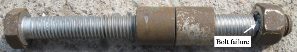
Bolts are one of the most common fasteners due to not only their convenience to install and uninstall parts but also their ability to connect a variety of materials. So, they are widely used in engineering, especially in automotive applications. At the same time, however, bolts also have their inherent weakness in that failures can happen quite quickly. There are mainly two types of bolt failures: loosening and fatigue. They often occur on any machines that move and vibrate. Loosening is usually caused by not enough torque being preloaded to the bolts. When the machine is vibrating, there are loads from all axles and thus forces acting on the bolts, which makes them loosen. Fatigue is similarly caused by axial loads but does not get loose. Instead, the micro-cracks decrease its ability to bear loads, which could eventually cause complete failure of the structure if no measure is taken to prevent further propagation [14] (Figure 1).
|
Figure 1. An example of bolt failure [15]. |
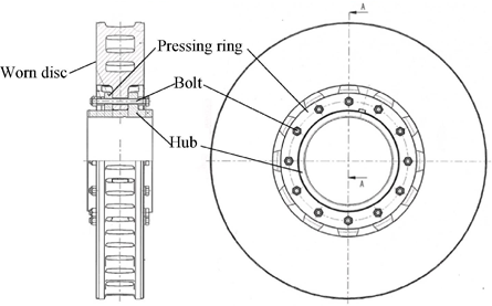
One typical example of fatigue failure of bolts is on anything connected to a shaft, like the wind turbines and the braking discs on vehicles, that is connected to a shaft using the bolts around the circumference (Figure 2).
|
Figure 2. An illustration of a braking disc [15]. |
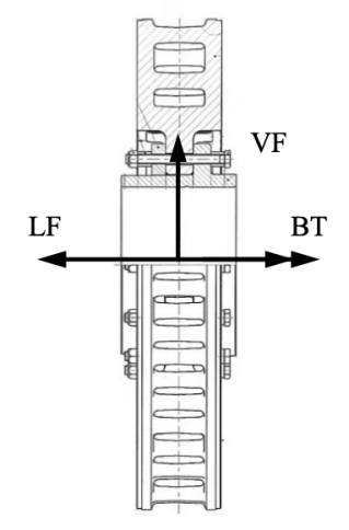
It is especially challenging for braking discs to slow down a vehicle from hundreds of kph to zero in seconds only by friction. When the braking clamp is engaged, it provides a substantial resisting force on the disc to change its motion which is also the entire vehicle's motion. In addition, since it is connected to the bolts and the shaft, all the bolts have a massive axile force caused by the resisting force that makes the vehicle stop (Figure 3).
|
Figure 3. The loads on a braking disc [15]. |
The loads from all directions create micro-cracks in the bolts. As the running time increases, the micro-cracks could propagate to become the cracks we can see and eventually break the bolts. If the fatigue is not found, it will accumulate and deteriorate, which eventually causes the structural failure that the bolt is broken into two pieces. One failed bolt might not be a fatal problem on a vehicle, which might cause it to slow down not as efficiently because there is always redundancy when designed. However, if several bolts fail, it will fail to decrease the speed of the vehicle as expected [15].
2.2. MIG Welding
Although MIG welding is an excellent method to connect materials, it has some disadvantages, just like other ways. Two main reasons may cause a break when tension between the two objects welds together. The first reason is that the materials had not completely melted and held together. Another reason is that the undercut reduces the effective cross-section of the base materials [16,17].
Overall, welding is a perfect way to decrease weight. In addition, they are stronger than standard connection methods, especially MIG welding. It makes producing lightweight vehicles possible. Nowadays, MIG welding is widely used in factories.[18]
2.3. FSW Welding
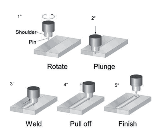
Friction stir welding (FSW) is a solid-state joining process that uses a non-consumable tool to join two facing workpieces without melting the work-piece material [19] (Figure 4).
|
Figure 4. Schematic representation of the FSW process [20]. |
It is a novel approach to welding dissimilar materials such as Magnesium (6XXX series) and Aluminum (AZ families), and it is joining for polymers that were still in the experiments. The main challenge of FSW is the presence of intermetallics (IMCs); they occur due to a non-equilibrium solidus temperature in the friction stir process since Liquefaction and solidification occur repeatedly. IMCs result in joint failures due to their low tensile properties and brittleness [21]. Some advanced FSW method was applied to diminish the IMCs. Firstly, water cooling can suppress the formation of IMCs by reducing the cooling time in this process. Laser hybrid friction stir welding was also used to join Al alloy to Mg alloy with Ni foil as filler material to reduce the formation of brittle Mg-Al IMCs.[22]. The three inherent issues of FSW are back support, weld thinning, and keyhole defect. During the friction stir process, the workpiece must be omnidirectionally fixed, which results in welding difficulties; penetration defects occur in the bottom of the joints; plunge depth thinning the joint, which quickly results in stress concentrations and fatigue damage [23]. Another common failure occurs with the welding tool [24]. Since FSW joining had already been applied to vehicles, these problems did not affect the overall performance of FSW; it is an appreciated option for lightweight vehicle designing.
In lightweight vehicle innovations, FSW has been widely applied in joining aluminum, magnesium, and other alloys lighter than traditional steel. In 2013, Honda developed a robotized FSW technology to weld steel and aluminum in a sub-frame of vehicles and applied it to a mass-production vehicle [25]. However, for the joining of other dissimilar lightweight materials, such as fiber-reinforced polymers, FSW does not work well [26]. Research shows that an FSW joint between carbon fiber-reinforced polymers has only a tensile shear strength of about 2.9kN, which is too low for heavy industrial applications. However, FSW joining for polymers has potential in the future. [27]
2.4. Riveting
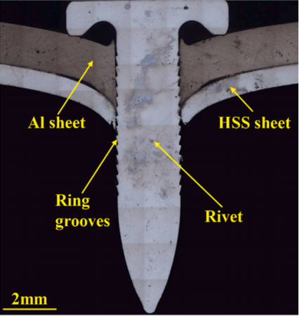
The function of the rivet is to join parts using adjoining surfaces. A straight piece of metal is attached through the part. The two ends are then formed at the joint, firmly joining the parts together. The self-piercing riveting process is the primary process used by most machines. There is a way called engineering that uses FEA to analyze, which is the most modern and economical way of optimal model realization. Due to further research on the joints, new materials with high-strength properties are implemented in assembling car body elements [28]. There is also a kind of electromagnetic-driven nailing riveted joint. Electromagnetic high-speed nailing (E-HSN) has been widely used in the mechanical area because of its high flexibility and excellent machine performance.[29]. The electromagnetic forming equipment charges the capacitor bank to store energy, closes the discharge switch after the energy is charged to the present value, and discharges energy through the flat coil placed in the riveting tooling. At the moment of discharge, the oscillating circuit composed of an energy storage capacitor, discharge coil, and internal resistance of the system generates alternating current, which generates an alternating magnetic field around the coil. The surface layer of the copper driving sheet attached to the coil induces alternating eddy currents due to the action of an alternating magnetic field, thereby generating an induced eddy current magnetic field. The coil's magnetic field and the eddy current's magnetic field create opposing repulsive forces that push the punch to compress the rivet and form the rivet head to lock the connecting plate. After fatigue testing, the fatigue life of his E-HSN joint at four stress levels was obtained. The traditional Basquin derivation equation fits the fatigue data: The results show that the joint has two typical fatigue failure modes. A cyclic stress of 253 MPa is the critical point for both failure modes. [Fig.3]
Mode1: At high cyclic stress, the load has been shared by the revising shank. The AI sheet provides a small horizontal load and subjects the rivet head, the rivet shank cannot withstand cyclical shear loads, and cracks occur. Finally, fatigue failure occurs within relatively short cyclic loading periods.
Mode2: At lower cyclic stresses, the cyclic load is insufficient to cause the rivet to fail immediately. After a load period, the interlocking structure between the sheet metal and the rivet grooves first fails due to friction and wear. A small gap is created between the rivet shank and the plate, allowing the rivet to tilt gradually. The rivet is subjected to shear and horizontal loads at this time, but the rivet shank can withstand relatively small shear loads. As the load continues to be applied, the rivet tilt and the horizontal load gradually increase. Fatigue failure eventually occurs between the rivet head and rivet shank until the rivet head can no longer withstand horizontal loads.[30] (Figure 5).
|
Figure 5.E-HSN equipment and cross-section geometry: the cross-section geometry of the joint. [30]. |
High-strength steels and aluminum alloys are becoming the preferred material for body components due to vehicle weight reduction when choosing the type of riveted joint. Body parts are usually connected by resistance welding [31]. Because it is difficult to join dissimilar metal parts such as iron and aluminum by resistance welding, the number of cases where mechanical joints such as SPR are used to join them is increasing. In addition, compared to bolting, mechanical clamping, and adhesive bonding, self-pierce riveting offers the advantages of solid and reliable connections, consistent riveting quality, no pre-drilling and dust during the riveting process, no toxic fume emissions or waste, and easy mechanization. As a result, SPR has attracted worldwide interest. After a series of previous experiments [32], fatigue tests show that the leading cause of joint failure is fretting wear between the rivet foot and the lower plate. Reducing corrosion time and fretting wear is a practical way to extend joint fatigue life.
2.5. Clinch
Clinching is similar to press forming. It is a process of cold forming of a small area of the material. The clinch connection between lightweight materials such as aluminum would be affected by the corrosion degradation phenomena and cause premature failure at a very low-stress level.
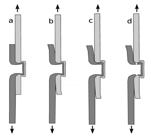
There are three stages of failure. At the first stage, as we observed a linear increase of the load versus displacement, the number of slopes was relatively constant, and the number of contact pressures between the aluminum and steel sheets was induced because the clinched button offered a forced mechanical joining and a shear resistance. At the second stage, the maximum load stage, the load-displacement curve has become non-linear, and the slope undergoes a progressive reduction. Moreover, contact friction is losing its effect on the total resistance of the joint. Finally, there is the final stage, the residual resistance stage, the residual strength of the joint will decrease progressively. Then there will be cracks in the button neck of the carbon steel button (Figure 6).
|
Figure 6. The clinched. |
2.6. Adhesion
Adhesion is one of the most effective methods used in vehicles for joining. For the reason that it is relatively low price and easy to apply. Adhesion is usually used for vehicles' decorations which do not need to withstand that much strength. For example, the simple leather inside the cars is applied with adhesion, and almost every vehicle needs this joining method. However, its downsides are unavoidable. Two of the most important factors which cause joining failure of adhesion are high temperature and moisture. This effect will be presented between the material and the adherents. Once the joining of adhesion is pulled and pressed, or it undergoes a temperature that it cannot hold, it will gradually lose its connection ability. To cope with this problem, we can enhance the heat-proof ability of the material. The researchers also invented a new high-strength material called Carbon-fiber-reinforced plastics (CFRPs). This advanced CF can withstand higher temperatures and more muscular stress and compression.[33] Likewise, if the air is wet, the glue will lose its ability to stick together. When it comes to metal material, adhesion cannot perform that well because many types of glue will cause corrosion on metal material, and people must process metal surfaces to avoid corrosion. This demonstrates that adhesion only presents its advantages in non-metal materials.[34] Carbon fiber can cooperate with adhesion pretty well because a layer of blister attached to CF can highly strengthen the adhesion joining method.[35] Furthermore, industrial plastic is also a suitable material applied to adhesion because it is light and can be expanded easily. Moreover, CF and industrial plastic can be applied to one joining to produce a mixed material joining.
2.7. Compare and contrast
For each joining that is strong enough, types of lightweight materials were discussed and marked in table 1.
Table 1. The types of dissimilar materials a joining method can connect.
Material pairs | Bolt | MIG welding | Friction Stir welding | Riveting | Clinched joining | Adhesion |
Carbon fiber reinforced polymers (CFRPs)+Carbon fiber reinforced polymers (CFRPs) | √ | √ | √ | |||
Carbon fiber reinforced polymers (CFRPs)+Aluminum alloy | √ | √ | √ | √ | ||
Carbon fiber reinforced polymers (CFRPs)+ Magnesium alloy | √ | √ | √ | |||
Carbon fiber reinforced polymers (CFRPs)+ Industrial plastics | √ | √ | √ | |||
Aluminum alloy+Aluminum alloy | √ | √ | √ | |||
Aluminum alloy+Magnesium alloy | √ | √ | √ | √ | √ | |
Aluminum alloy+Industrial plastics | √ | |||||
Magnesium alloy+Magnesium alloy | √ | √ | √ | |||
Magnesium alloy+Industrial plastics | √ | √ | √ | √ | ||
Industrial plastics+Industrial plastics | √ | √ | √ |
Firstly, from the table above, bolts, FSW, and rivets have much broader applications when joining different materials than MIG, clinch, and adhesion. Secondly, comparing the pull-out strength, bolts have the highest strength, and rivets are the second highest due to their threaded nature. An anchor bolt of 12 mm Ф with an embedment length of 70 mm has 47kN pullout strength [36], while a self-piercing rivet has about 34kN pullout strength [10]. Thirdly, bolts have a more straightforward manufacturing process than rivets. It is also more convenient to join two materials with bolts than with rivets. Admittedly, both bolts and rivets bring additional weights to the structure, while FSW and MIG welding do not. In conclusion, bolts are the most appropriate choice for most applications, considering the materials being joined, their high pullout strength, and the installation convenience, while riveting joints are the second.
3. Conclusion
This paper reviewed six types of advanced joining that could be applied to join dissimilar materials to meet fuel efficiency.
Bolts are the most common type of joining because it is not limited by the materials being joined. For example, bolts can be used to join carbon fiber, aluminum alloy, magnesium alloy, plastic, etc. The only restriction of bolts is their failure, whether loosening or fatigue. However, it is caused by either excessive loads while the machine is running or not enough torque being pre-installed. So the only restriction of bolts has nothing to do with the joined materials. Thus, bolts can join the most variety of materials with different combinations.
MIG Welding is one of the most popular ways to connect two metals. Nowadays, MIG welding is used widely in the industrial field. For example, the inside structure of the car usually uses welding to connect. However, materials that do not include metal cannot be connected by welding. Overall, welding is a stable and safe way to combine metal materials.
Friction Stir Welding (FSW) has been widely applied to join aluminum alloy plates to magnesium plates. A study found that FSW has the potential to join thermoplastic polymers and polymer matrix composites, but FSW for polymers hasn't been applied widely in practice.
Riveting joints are currently used in machines because they can connect many types of materials.Electromagnetic High-Speed-Nailing (E-HSN) has wide application prospects due to the advantage of high flexibility, unilateral operation, and excellent performance. This paper systematically developed the fatigue behavior of E-HSN joints with aluminum alloy and high-strength steel structure.
Clinching is a new type of joining which is lightweight and can connect a variety of materials. It fits automatized environment-friendly mass production. Since car companies are trying to lower the cost, it will be trendy in the future. It also can connect most new materials which use the latest technology. So, clinching can decrease fuel consumption and be suitable for car production.
Adhesion only gains its advantages when it comes to non-metal. And the reason is that before the metal materials are about to be stuck together, they need to be processed on their surfaces because the adhesion materials might erode the metals, consequently affecting the joining performance. Therefore, non-metal materials such as carbon fiber and industrial plastic are most suitable for adhesion.
So, among the six types of joining that are reviewed, bolts are considered the best choice to connect different types of materials without the limitation of the types of materials that are joined. Thus, bolts are widely applied on applications that require an overall low weight, which decreases fuel consumption and thus increases fuel efficiency.
References
[1]. K.Kawajiri, M.Kobayashi and K.Sakamoto, “Lightweight materials equal lightweight greenhouse gas emissions?: A historical analysis of greenhouse gases of vehicle material substitution,”Journal of Cleaner Production, vol.253, Apr.2020, 110985, DOI:10.1016/j.jclepro.2019.119805.
[2]. “16 Fighting Falcon News,” F. [Online]. Available: www.f-16.net/f-16-news-article21.html.
[3]. MIG Welding Process (Explained with Definition & Diagram)” in KNORDS Learning., vol.25, pp1-10, 2007.08.21
[4]. “MIG Welding | What is MIG Welding and How Does it Work?” in American Industrial Supplies.
[5]. R.S. Mishra and Z.Y. Ma, “Friction stir welding and processing,” Materials Science and Engineering: R: Reports, vol.50, pp.1-78, Aug.2005, doi:10.1016/j.mser.2005.07.001.
[6]. X. He, F. Gu and A. Ball, “A review of numerical analysis of friction stir welding,” Progress in Materials Science, vol.65, pp.1-66, Aug.2014, doi:10.1016/j.pmatsci.2014.03.003.
[7]. H.Zhang, S.Lin, L.Wu, J.Feng and G.Luan, “Current progress and prospect of friction stir welding,” Transaction of the China Welding Institution , vol.24, No.3, pp.91-96, Jun.2003.
[8]. A. Arora, T. DebRoy and H.K.D.H. Bhadeshia, “Back-of-the-envelope calculations in friction stir welding – Velocities, peak temperature, torque, and hardness,” Acta Materialia, vol.59, No.5, pp.2020-2028, Mar.2011, doi: 10.1016/j.actamat.2010.12.001.
[9]. C. Gong, Z. Fan, L. Cheng, J. Deng,“Predictions of the total electromagnetic repulsion force in electromagnetic riveting process: Numerical analysis model and experiments,” Journal of Manufacturing Processes, vol.69, Aug.2021, pp.656-670, doi:10.1016/j.jmapro.2021.08.022.
[10]. J. Mucha,“The failure mechanics analysis of the solid self-piercing riveting joints”,Engineering Failure Analysis,vol.47, pp.77-88, Nov.2014, doi:10.1016/j.engfailanal.2014.10.008.
[11]. Q. Collette, I. Wouters and L. Lauriks Department of Architectural Engineering (ARCH), “Evolution of historical riveted connections: joining typologies, installation techniques and calculation methods,” WIT Transactions on The Built Environment, vol.118, doi:10.2495/STR110251
[12]. M.F. Othman, A.R. Bushroa & Wan Normimi Roslini Abdullah (2015) Evaluation techniques and improvements of adhesion strength for TiN coating in tool applications: a review, Journal of Adhesion Science and Technology, 2015, pp. 569-591, DOI: 10.1080/01694243.2014.997379
[13]. S.J. Marshall, S.C. Bayne, R. Baier, A.P. Tomsia, G.W. Marshall, “A review of adhesion science,” in Dental materials, 2010, pp. e11-e16, dio: 10.1016/j.dental.2009.11.157.
[14]. F. Casanova and C. Mantilla, “Fatigue failure of the bolts connecting a Francis turbine with the shaft,” Engineering Failure Analysis, 14-Mar-2018. [Online]. Available: https://www.sciencedirect.com/science/article/abs/pii/S1350630716311128.
[15]. X. Shen, L. Lu, and D. Zeng, “Fatigue failure analysis of high strength bolts used for high-speed railway vehicle braking discs,” Engineering Failure Analysis, 02-Jun-2020. [Online]. Available: https://www.sciencedirect.com/science/article/abs/pii/S1350630719319028.
[16]. J. Bian, H. Mohrbacher, J.-S. Zhang, Y.-T. Zhao, H.-Z. Lu, and H. Dong, “Application potential of high performance steels for weight reduction and efficiency increase in commercial vehicles - Advances in Manufacturing,” SpringerLink, 03-Mar-2015. [Online]. Available: https://link.springer.com/article/10.1007/s40436-015-0102-9.
[17]. “MIG Welding Process (Explained with Definition & Diagram)” in KNORDS Learning., available: knordslearning.com/what-is-mig-welding/
[18]. “MIG Welding Process (Explained with Definition & Diagram)” in KNORDS Learning., vol.25, pp1-10, 2007.08.21
[19]. Li, K., Jarrar, F., Sheikh-Ahmad, J., & Ozturk, F. (2017). Using coupled Eulerian Lagrangian formulation for accurate modeling of the friction stir welding process. Procedia Engineering, 207, 574–579. doi:10.1016/j.proeng.2017.10.1023
[20]. Adamowski J, Szkodo M. Friction Stir Welds (FSW) of aluminium alloy AW6082-T6[J]. Journal of Achievements in Materials and Manufacturing Engineering, 2007, 20(1-2): 403-406.
[21]. O.Kayode and E.T.Akinlabi, “An overview on joining of aluminium and magnesium alloys using friction stir welding (FSW) for automotive lightweight applications,” Material Research Express, vol.6, No.11, pp.1-27, Oct.2019, DOI:10.1088/2053-1591/ab3262.
[22]. L. H. Shah, N. H. Othman and A. Gerlich, “Review of research progress on aluminium–magnesium dissimilar friction stir welding,” Science and Technology of Welding and Joining, vol.23, No.3, pp.256-270, DOI: 10.1080/13621718.2017.1370193.
[23]. X.Meng, Y.Huang, J.Cao, J.Shen, and J.F.Santos, “Recent progress on control strategies for inherent issues in friction stir welding,” Progress in Materials Science, vol.115, Jan.2021, doi:10.1016/j.pmatsci.2020.100706.
[24]. Y. Du, T. Mukherjee, P. Mitra, and T. DebRoy, “Machine learning based hierarchy of causative variables for tool failure in friction stir welding,” Acta Materialia, vol.192, pp.67-77, Jun.2020, doi:10.1016/j.actamat.2020.03.047.
[25]. Y.Kusuda, “Honda develops robotized FSW technology to weld steel and aluminum and applied it to a mass‐production vehicle,”Industrial Robot, vol. 40, No. 3, pp.208-212, DOI:10.1108/01439911311309889.
[26]. D.Zhang, Q.Zhang, X.Fan and S.Zhao, “Review on Joining Process of Carbon Fiber-Reinforced Polymer and Metal: Methods and Joining Process,” Rare Metal Materials and Engineering, vol.47, No.12, pp.3686-3696, Jan.2019, DOI:10.1016/S1875-5372(19)30018-9.
[27]. A.R.Patel, C.G.Dalwadi, H.G.Rana, “A review: dissimilar material joining of metal to polymer using friction stir welding (FSW),” Int J Sci Technol Eng, vol.2, No.10, pp.702-706, Apr.2016.
[28]. 1Jacek Mucha, The failure mechanics analysis of the solid self-piercing riveting joints, Engineering Failure Analysis, Vol 47,Part A, 2015, Pages 77-88, ISSN 1350-6307, doi.org/10.1016/j.engfailanal.2014.10.008.
[29]. Hao Jiang, Guangyao Li, Xu Zhang, Junjia Cui, Fatigue and failure mechanism in carbon fiber reinforced plastics/aluminum alloy single lap joint produced by electromagnetic riveting technique, Composites Science and Technology, Vol 152, 2017, Pages 1-10, ISSN 0266-3538, doi.org/10.1016/j.compscitech.2017.09.004.
[30]. Hao Jiang, Bingkun Li, Guangyao Li, Junjia Cui, Failure behavior of electromagnetic driven nailing riveted joint for Al/steel structures subjected to fatigue loading, Engineering Failure Analysis, Vol 132, 2022, 105941, ISSN 1350-6307, doi.org/10.1016/j.engfailanal.2021.105941.
[31]. Nikolaos Karathanasopoulos, Dirk Mohr, Strength and Failure of Self-Piercing Riveted Aluminum and Steel Sheet Joints: Multi-axial Experiments and Modeling, Journal of Advanced Joining Processes, Vol 5, 2022, 100107, ISSN 2666-3309,doi.org/10.1016/j.jajp.2022.100107.
[32]. Zhi-Chao Huang, Ying-Lian Jia, Yu-Qiang Jiang, Yong-Chao Zhang, Mechanical properties and fatigue failure mechanisms of purely self-piercing riveted (SPR) and hybrid (SPR-bonded) joints under salt spray environment, Journal of Materials Research and Technology, Vol 20, 2022, Pages 2501-2517, ISSN 2238-7854, doi.org/10.1016/j.jmrt.2022.08.024.
[33]. Lun Q, Xiaolong W, Le Y, Biao W, Xueyu W, Hongxing L, “Improving the high-temperature adhesion strength between an Al/polysiloxane coating and a polyimide/carbon fiber substrate by a thermal pre-treatment step and structural design”, Progress in Organic Coatings, vol. 168, July 2022, https://doi.org/10.1016/j.porgcoat.2022.106888
[34]. Rupam G, Atul K. M, Gaurav M, “A review on recent development in carbon fiber reinforced polyolefin composites”, Composites Part C: Open Access, vol. 8, July 2022, https://doi.org/10.1016/j.jcomc.2022.100279
[35]. Kouhei K, SulChan K, Tetsuya Y, Keisuke K, Masaaki N, “Structural design to enhance mechanical properties of carbon-fiber-reinforced thermoplastics using colloidal particles and soft and hard resins”, Composites Part C: Open Access, vol. 6, October 2021, https://doi.org/10.1016/j.jcomc.2021.100211
[36]. Muhammad Saleem, “Evaluating the pull-out load capacity of steel bolt using Schmidt hammer and ultrasonic pulse velocity test”Structural Engineering and Mechanics, Vol. 65, No. 5 (2018) 601-609, doi.org/10.12989/sem.2018.65.5.601
Cite this article
Luo,Q.;Tan,X.;Zhang,J.;Fang,Y. (2023). A Review of Six Joining Methods for Connecting Different Materials in Lightweight Automotive Applications. Applied and Computational Engineering,3,161-171.
Data availability
The datasets used and/or analyzed during the current study will be available from the authors upon reasonable request.
Disclaimer/Publisher's Note
The statements, opinions and data contained in all publications are solely those of the individual author(s) and contributor(s) and not of EWA Publishing and/or the editor(s). EWA Publishing and/or the editor(s) disclaim responsibility for any injury to people or property resulting from any ideas, methods, instructions or products referred to in the content.
About volume
Volume title: Proceedings of the 3rd International Conference on Materials Chemistry and Environmental Engineering (CONF-MCEE 2023)
© 2024 by the author(s). Licensee EWA Publishing, Oxford, UK. This article is an open access article distributed under the terms and
conditions of the Creative Commons Attribution (CC BY) license. Authors who
publish this series agree to the following terms:
1. Authors retain copyright and grant the series right of first publication with the work simultaneously licensed under a Creative Commons
Attribution License that allows others to share the work with an acknowledgment of the work's authorship and initial publication in this
series.
2. Authors are able to enter into separate, additional contractual arrangements for the non-exclusive distribution of the series's published
version of the work (e.g., post it to an institutional repository or publish it in a book), with an acknowledgment of its initial
publication in this series.
3. Authors are permitted and encouraged to post their work online (e.g., in institutional repositories or on their website) prior to and
during the submission process, as it can lead to productive exchanges, as well as earlier and greater citation of published work (See
Open access policy for details).
References
[1]. K.Kawajiri, M.Kobayashi and K.Sakamoto, “Lightweight materials equal lightweight greenhouse gas emissions?: A historical analysis of greenhouse gases of vehicle material substitution,”Journal of Cleaner Production, vol.253, Apr.2020, 110985, DOI:10.1016/j.jclepro.2019.119805.
[2]. “16 Fighting Falcon News,” F. [Online]. Available: www.f-16.net/f-16-news-article21.html.
[3]. MIG Welding Process (Explained with Definition & Diagram)” in KNORDS Learning., vol.25, pp1-10, 2007.08.21
[4]. “MIG Welding | What is MIG Welding and How Does it Work?” in American Industrial Supplies.
[5]. R.S. Mishra and Z.Y. Ma, “Friction stir welding and processing,” Materials Science and Engineering: R: Reports, vol.50, pp.1-78, Aug.2005, doi:10.1016/j.mser.2005.07.001.
[6]. X. He, F. Gu and A. Ball, “A review of numerical analysis of friction stir welding,” Progress in Materials Science, vol.65, pp.1-66, Aug.2014, doi:10.1016/j.pmatsci.2014.03.003.
[7]. H.Zhang, S.Lin, L.Wu, J.Feng and G.Luan, “Current progress and prospect of friction stir welding,” Transaction of the China Welding Institution , vol.24, No.3, pp.91-96, Jun.2003.
[8]. A. Arora, T. DebRoy and H.K.D.H. Bhadeshia, “Back-of-the-envelope calculations in friction stir welding – Velocities, peak temperature, torque, and hardness,” Acta Materialia, vol.59, No.5, pp.2020-2028, Mar.2011, doi: 10.1016/j.actamat.2010.12.001.
[9]. C. Gong, Z. Fan, L. Cheng, J. Deng,“Predictions of the total electromagnetic repulsion force in electromagnetic riveting process: Numerical analysis model and experiments,” Journal of Manufacturing Processes, vol.69, Aug.2021, pp.656-670, doi:10.1016/j.jmapro.2021.08.022.
[10]. J. Mucha,“The failure mechanics analysis of the solid self-piercing riveting joints”,Engineering Failure Analysis,vol.47, pp.77-88, Nov.2014, doi:10.1016/j.engfailanal.2014.10.008.
[11]. Q. Collette, I. Wouters and L. Lauriks Department of Architectural Engineering (ARCH), “Evolution of historical riveted connections: joining typologies, installation techniques and calculation methods,” WIT Transactions on The Built Environment, vol.118, doi:10.2495/STR110251
[12]. M.F. Othman, A.R. Bushroa & Wan Normimi Roslini Abdullah (2015) Evaluation techniques and improvements of adhesion strength for TiN coating in tool applications: a review, Journal of Adhesion Science and Technology, 2015, pp. 569-591, DOI: 10.1080/01694243.2014.997379
[13]. S.J. Marshall, S.C. Bayne, R. Baier, A.P. Tomsia, G.W. Marshall, “A review of adhesion science,” in Dental materials, 2010, pp. e11-e16, dio: 10.1016/j.dental.2009.11.157.
[14]. F. Casanova and C. Mantilla, “Fatigue failure of the bolts connecting a Francis turbine with the shaft,” Engineering Failure Analysis, 14-Mar-2018. [Online]. Available: https://www.sciencedirect.com/science/article/abs/pii/S1350630716311128.
[15]. X. Shen, L. Lu, and D. Zeng, “Fatigue failure analysis of high strength bolts used for high-speed railway vehicle braking discs,” Engineering Failure Analysis, 02-Jun-2020. [Online]. Available: https://www.sciencedirect.com/science/article/abs/pii/S1350630719319028.
[16]. J. Bian, H. Mohrbacher, J.-S. Zhang, Y.-T. Zhao, H.-Z. Lu, and H. Dong, “Application potential of high performance steels for weight reduction and efficiency increase in commercial vehicles - Advances in Manufacturing,” SpringerLink, 03-Mar-2015. [Online]. Available: https://link.springer.com/article/10.1007/s40436-015-0102-9.
[17]. “MIG Welding Process (Explained with Definition & Diagram)” in KNORDS Learning., available: knordslearning.com/what-is-mig-welding/
[18]. “MIG Welding Process (Explained with Definition & Diagram)” in KNORDS Learning., vol.25, pp1-10, 2007.08.21
[19]. Li, K., Jarrar, F., Sheikh-Ahmad, J., & Ozturk, F. (2017). Using coupled Eulerian Lagrangian formulation for accurate modeling of the friction stir welding process. Procedia Engineering, 207, 574–579. doi:10.1016/j.proeng.2017.10.1023
[20]. Adamowski J, Szkodo M. Friction Stir Welds (FSW) of aluminium alloy AW6082-T6[J]. Journal of Achievements in Materials and Manufacturing Engineering, 2007, 20(1-2): 403-406.
[21]. O.Kayode and E.T.Akinlabi, “An overview on joining of aluminium and magnesium alloys using friction stir welding (FSW) for automotive lightweight applications,” Material Research Express, vol.6, No.11, pp.1-27, Oct.2019, DOI:10.1088/2053-1591/ab3262.
[22]. L. H. Shah, N. H. Othman and A. Gerlich, “Review of research progress on aluminium–magnesium dissimilar friction stir welding,” Science and Technology of Welding and Joining, vol.23, No.3, pp.256-270, DOI: 10.1080/13621718.2017.1370193.
[23]. X.Meng, Y.Huang, J.Cao, J.Shen, and J.F.Santos, “Recent progress on control strategies for inherent issues in friction stir welding,” Progress in Materials Science, vol.115, Jan.2021, doi:10.1016/j.pmatsci.2020.100706.
[24]. Y. Du, T. Mukherjee, P. Mitra, and T. DebRoy, “Machine learning based hierarchy of causative variables for tool failure in friction stir welding,” Acta Materialia, vol.192, pp.67-77, Jun.2020, doi:10.1016/j.actamat.2020.03.047.
[25]. Y.Kusuda, “Honda develops robotized FSW technology to weld steel and aluminum and applied it to a mass‐production vehicle,”Industrial Robot, vol. 40, No. 3, pp.208-212, DOI:10.1108/01439911311309889.
[26]. D.Zhang, Q.Zhang, X.Fan and S.Zhao, “Review on Joining Process of Carbon Fiber-Reinforced Polymer and Metal: Methods and Joining Process,” Rare Metal Materials and Engineering, vol.47, No.12, pp.3686-3696, Jan.2019, DOI:10.1016/S1875-5372(19)30018-9.
[27]. A.R.Patel, C.G.Dalwadi, H.G.Rana, “A review: dissimilar material joining of metal to polymer using friction stir welding (FSW),” Int J Sci Technol Eng, vol.2, No.10, pp.702-706, Apr.2016.
[28]. 1Jacek Mucha, The failure mechanics analysis of the solid self-piercing riveting joints, Engineering Failure Analysis, Vol 47,Part A, 2015, Pages 77-88, ISSN 1350-6307, doi.org/10.1016/j.engfailanal.2014.10.008.
[29]. Hao Jiang, Guangyao Li, Xu Zhang, Junjia Cui, Fatigue and failure mechanism in carbon fiber reinforced plastics/aluminum alloy single lap joint produced by electromagnetic riveting technique, Composites Science and Technology, Vol 152, 2017, Pages 1-10, ISSN 0266-3538, doi.org/10.1016/j.compscitech.2017.09.004.
[30]. Hao Jiang, Bingkun Li, Guangyao Li, Junjia Cui, Failure behavior of electromagnetic driven nailing riveted joint for Al/steel structures subjected to fatigue loading, Engineering Failure Analysis, Vol 132, 2022, 105941, ISSN 1350-6307, doi.org/10.1016/j.engfailanal.2021.105941.
[31]. Nikolaos Karathanasopoulos, Dirk Mohr, Strength and Failure of Self-Piercing Riveted Aluminum and Steel Sheet Joints: Multi-axial Experiments and Modeling, Journal of Advanced Joining Processes, Vol 5, 2022, 100107, ISSN 2666-3309,doi.org/10.1016/j.jajp.2022.100107.
[32]. Zhi-Chao Huang, Ying-Lian Jia, Yu-Qiang Jiang, Yong-Chao Zhang, Mechanical properties and fatigue failure mechanisms of purely self-piercing riveted (SPR) and hybrid (SPR-bonded) joints under salt spray environment, Journal of Materials Research and Technology, Vol 20, 2022, Pages 2501-2517, ISSN 2238-7854, doi.org/10.1016/j.jmrt.2022.08.024.
[33]. Lun Q, Xiaolong W, Le Y, Biao W, Xueyu W, Hongxing L, “Improving the high-temperature adhesion strength between an Al/polysiloxane coating and a polyimide/carbon fiber substrate by a thermal pre-treatment step and structural design”, Progress in Organic Coatings, vol. 168, July 2022, https://doi.org/10.1016/j.porgcoat.2022.106888
[34]. Rupam G, Atul K. M, Gaurav M, “A review on recent development in carbon fiber reinforced polyolefin composites”, Composites Part C: Open Access, vol. 8, July 2022, https://doi.org/10.1016/j.jcomc.2022.100279
[35]. Kouhei K, SulChan K, Tetsuya Y, Keisuke K, Masaaki N, “Structural design to enhance mechanical properties of carbon-fiber-reinforced thermoplastics using colloidal particles and soft and hard resins”, Composites Part C: Open Access, vol. 6, October 2021, https://doi.org/10.1016/j.jcomc.2021.100211
[36]. Muhammad Saleem, “Evaluating the pull-out load capacity of steel bolt using Schmidt hammer and ultrasonic pulse velocity test”Structural Engineering and Mechanics, Vol. 65, No. 5 (2018) 601-609, doi.org/10.12989/sem.2018.65.5.601