


1. Introduction
From the day James Watt modified the steam engine, it witnessed a splendid century that human society had developed unprecedentedly [1]. Thanks to the industrial revolution, people's food, clothing, housing and transportation have been greatly improved. At the same time, the improvement of the engine has greatly liberated the productivity of human beings. Besides, the use of the engine is also increasing, not only for machine tools and trains, but also for the emergence of cars to solve the need for people to travel long distances.
This paper will investigate from three aspects [2]. First of all, this paper mainly introduces the four stroke internal combustion engine, and introduces the Otto cycle with the gasoline engine as an example [3].Secondly, hydrogen fuel cell will be introduced around PAFC, SOFC and PEMFC, which contains different energy conversion forms and structures of three fuel cells. Finally, the third part is about hybrid engine, which contains two different engines that work independently for motor and internal combustion engine and work simultaneously for motor and internal combustion engine.
2. Comparison and analysis of traditional and alternative engines on vehicles
Humans are currently over-dependent on fossil fuels, responsible for almost three-fourths of the emissions from human activities in the last 20 years [4]. These emissions contribute to acid rain and global warming [1]. Take the greenhouse gases emitted in 2020 as an example; even though there was a decline, the concentration of in the atmosphere reached 412.5 ppm (parts per million), which is about 50% higher than the value before the industrial revolution addition, fossil fuels such as coal, natural gas, and gasoline will produce not only greenhouse gases but also toxic exhausts like carbon monoxide due to incomplete combustion. Not only that, fossil fuels are nonrenewable energy sources. Under this section, people need to find new energy sources and use engines based on them [5].
In addition, all traditional engines are based on the Carnot cycle, and their thermal efficiency will be limited to under 60%. However, the electric motors on vehicles nowadays can work with an efficiency of about 90%. Even though new engines could be more environmentally friendly, the cost of production of using them can be prohibitive. Moreover, using alternative engines is not as convenient as traditional engines.
2.1. Internal combustion engines
In 1670, Dutch physicist Huygens invented the earliest propellant internal combustion engine. Since then, Etienne Leno has built the first natural gas engine. Although its thermal efficiency is only 2% - 3%, it represents the beginning of the internal combustion engine era. In 1876, German engineer Nicholas Otto made the “new Otto engine”. This new engine can be compressed to 2.36 bar, with an efficiency of about 12%, about twice than that of other engines. In addition, the "new Otto engine" is also the earliest four stroke engine and the prototype of the Otto cycle [6].
There are many different types of internal combustion engines; they can be classified by: the fuel used, the number of strokes in a working cycle, the cooling methods, and so on. The internal combustion engine has been the most popular engine for more than a century due to its high thermal efficiency and low cost of production. The number of internal combustion engines exceeds all the other kinds of machines [7]. It is the largest and most widely used thermal machinery in the world.
However, there are also some drawbacks. Firstly, using poor and solid fuels will damage its components of it. Secondly, the noise and the toxic gases in the exhaust are detrimental to the environment. The history of the internal combustion engines over the one and a half-century has been a history of humans trying to overcome these problems. Figure 1 shows the structure of a four stroke engine.
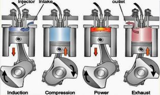
Figure 1. The construction of the four-stroke engine.
2.2. 4-stroke engine
Since this article is about vehicle engines, internal combustion engines are the most popular cars nowadays [8]. The 4-stroke engines will represent the traditional engines in this article. 4-stroke engines are mainly made from three components, which are the piston, the connecting rod, and the crankshaft.
The piston will move up and down linearly in the combustion space (a cylinder). Each time it travels up or down once, it will be referred to as a stroke as the piston travels linearly. The crankshaft rotates, so it transfers the linear motion from the piston into the rotary motion of the crankshaft. Every up and down motion of the piston will lead to a full rotation (revolution) of the crankshaft.That means every two strokes translates to one crankshaft revolution. On the top of the cylinder, there are valves to allow air in and exhaust gases out of the combustion chamber [9]. At the end of the fuel injector, the nozzle will inject fuel into the combustion space.
2.3. 4 strokes (petrol engines as an example)
Stroke one (intake stroke): The piston will move down to the bottom dead center, with inlet valves open to allow the air in. As the piston is moving down, it creates a vacuum that draws the air in.
Stroke two (compression stroke): The piston will then move up to its top dead center, with inlet valves closed. This process will compress the air in the combustion chamber. At the same time, the nozzle will inject atomized fuel, which will be lighted by the spark plug.
Stroke three (power stroke): The mixture of atomized fuel and air will explode and push the stroke downwards. This process converts chemical energy into mechanical energy.
Stroke four (exhaust stroke): The piston travel back up from the bottom dead center to the top dead center with outlet valves open to push out the exhaust gas.
2.4. Otto cycle (4 stroke cycle)
Process 1-2: Isentropic compression (intake stroke)
Process 2-3: Constant volume heat addition (compression stroke)
Process 3-4: Isentropic expansion (power stroke)
Process 4- 1: Constant volume heat rejection (exhaust stroke)
The otto cycle is an ideal cycle for internal combustion engines. However, the thermal efficiency of gasoline automotive engines is around 25% to 30%. Figure 2 is the pressure volume diagram of Otto cycle.
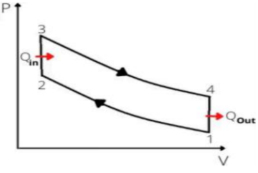
Figure 2. Pressure- volume diagram of the Otto cycle.
2.5. Emissions for vehicles using traditional engines
According to the data from the United States Environmental Protection Agency, there are 4.6 tons of carbon dioxide emitted by typical passenger verticals as an average. Furthermore, the amount of emitted is mainly based on the fuel and the thermal efficiency of the engine in it. The emissions for gasoline are about 2347.7 g/L, whereas the emissions for diesel are about 2689.3g/L which is 15.5% greater.
However, the combustion of gasoline and diesel is not the only source of emissions when using 4- stroke engines. After the crude oil is extracted, it needs to be transported to a refinery where it is turned into gasoline or diesel, and then it is often transported by car to the petrol stations. All of these steps require energy, so the process of generating that energy (such as electricity) also emits carbon dioxide and other greenhouse gases. In addition to the carbon dioxide mentioned above, there are some other greenhouse gases emitted such as methane, nitrogen oxide (O), and carbon monoxide (CO). That exhaust will not only leads to global warming but also be toxic to human beings and other animals. Moreover, gases like O and will react with the water in the atmosphere, and cause acid rains that are detrimental to the forests, and buildings [5].
3. Hydrogen fuel cell
Fuel cell is a kind of battery which need the help of fuel. Compared with traditional energy store battery, fuel cell can transform chemical energy into electric energy. Such devices can provide enough energy for the vehicles. From the perspective of the structure of the fuel cell, the driving system, mainly covers the hydrogen storage system, drive motor, power battery and fuel cell device. Hydrogen fuel cell can make the internal hydrogen and oxygen mixed combustion, providing sufficient electricity and making the vehicle have sufficient driving force [6]. By using fuel cells as power, cars can not only become more efficient and significantly reduce harmful emissions, but also can reduce noise and vibration during vehicle operation. Therefore, fuel cell vehicles will be an important development trend of the future automobile, and fuel cell vehicle technology is also becoming the focus of research in the automotive field.
The fuel cell is a device which uses a specific fuel that generates a current through a proton exchange membrane and a catalytic layer that can provide continuous electricity as long as the external source continuously supplies fuel (such as hydrogen or methanol). By using a technology called proton exchange membrane, the hydrogen under the proton exchange membrane covered with catalyst. In the anode, hydrogen catalytic decomposition into a proton, the proton through the proton exchange membrane to the cathode, in this process of hydrogen decomposition release electrons, electron through the load is drawn to the cathode, thus produce the electricity. At the anode it passes through the action of a proton exchange membrane and a catalyst, and at the cathode the protons combine with oxygen and electrons. In other words, the hydrogen inside the fuel cell chemically reacts with the oxygen in the air, which can produce a current, can also be explained as the reverse reaction of electrolysis water [7].
Excepting supplying hydrogen at the anode, the fuel cell also collects hydrogen protons (H+) to release electrons, and captures electrons through a load at the cathode to generate electricity. The proton exchange membrane function simply allows proton H + passage and binds to oxygen in the cathode to produce water. This water is distributed in the air in the form of water vapor at the reaction temperature (a water recovery device for high-power fuel cells used in cars). By using hydrogen as fuel cells, the generated water is pure and drinkable, while aqueous solutions generated by methanol may produce toxic substances such as formaldehyde and are not drinkable.
According to the working principle mentioned above, the fuel cell can operate continuously and provide electricity as long as the fuel is constantly replenished. Companies have developed a pen shaped tube fuel fuel cell (similar to the lighter form), but the fuel tube must often replaced, which is easy to make the electrode catalyst of platinum (Pt) and ruthenium (Ru) particle condensation, the aging performance, so as to reduce the life of the fuel cell, is currently being improved.
3.1. Phosphoric Acid Fuel Cell (PAFC)
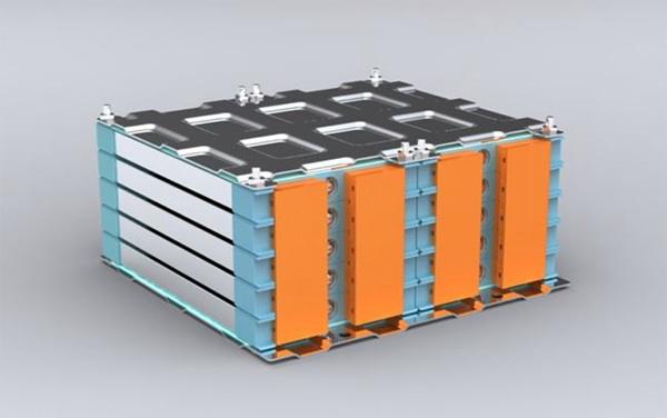
Figure 3. Basic structure of PAFC.
Phosphoric acid is one of the fastest growing commercial fuel cells. As its name suggests, liquid phosphoric acid used in the silicon carbon matrix contains phosphorus just like the dog electrolyte. Phosphoric acid fuel cells have fewer fuel cells than membrane fuel cells, but they need platinum catalysts to accelerate electrode reactions. The anode and cathode reactions in the proton exchange membrane fuel cell may be the same, but because of the high operating temperature, the reaction cell on the floor is faster than the fuel cell on the proton variable membrane [8]. Figure 3 shows the basic structure of PAFC.
Phosphoric acid fuel cells are less efficient than other fuel cells, about 40 percent, and heat longer than proton exchange membrane fuel cells. Although phosphoric acid fuel cells have the above disadvantages, this kinds of cells also have many advantages, such as simple structure, stability, and low electrolyte volatilization. Over the past 20 years, a lot of research has successfully used phosphoric acid fuel cells, and many 0.2-20 MW power-generating plants have been installed around the world to power hospitals, schools and small power stations. It uses phosphoric acid as electrolyte and cheap carbon material as skeleton [9].
3.2. Solid Oxide Fuel Cell (SOFC)
SOFC is an all-solid-state chemical power generation device that directly converts the efficient and environmentally friendly chemical energy stored in fuel and oxidants into electric energy at medium and high temperature. A fuel cell, widely considered as widely used as proton exchange membrane fuel cell (PEMFC), is adaptable to fuel in a variety of fuels, including carbon-based fuels. These characteristics make the total fuel power generation efficiency with a potential of more than 60% in a single cycle, while the overall system efficiency is as high as 85%, with a SOFC power density of 1MW/M3, and possibly up to 3MW/M3 for a block design. In fact, SOFC can be used for power generation, thermoelectricity reuse, transportation, space space and many other fields, which is known as the green energy of the 21st century. Figure 4 shows the internal chemical reaction of SOFC.
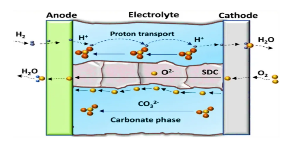
Figure 4. Internal chemical reaction inside SOFC.
3.3. Proton-exchange Membrane Fuel Cell (PEMFC)
The basic structure of proton exchange membrane fuel cell is mainly composed of proton exchange membrane, catalyst layer, diffusion layer, and collector plate (also known as bipolar plate). The polymer electrolyte membrane is covered by a carbon-based catalyst, which directly makes contact with both the diffusion layer and the electrolyte to reach the maximum interaction surface. The catalyst forms an electrode, above which directly is a diffusion layer. The combination of an electrolyte, a catalyst layer, and a gas diffusion layer is referred to as a membrane-electrode assembly.
PEM is the core component of proton exchange membrane fuel cell, whose thickness of only 50~180um, but its micro-structure is very complex. It provides a channel for proton transmission, and also serves as a diaphragm to separate the fuel of the anode from the oxidizer of the cathode. Its performance directly affects the performance and life of the battery. It is very different from the diaphragm used in general chemical power supply, not only serve as a diaphragm material to isolate the reversed pole reaction gas, but also serve as the electrolyte and electrode active substance (electrocatalyst). In addition, PEM is also a permeable film with optional permeability under certain temperature and humidity. In the polymer structure of proton exchange membrane, it contains multiple ion groups, which only allows hydrogen ions come in, and refuse other kinds of particles. The quality of proton exchange membrane is very high, which must have good proton conductivity, good thermal and chemical stability, low gas permeability, and moderate water content. Figure 5 shows the basic structure of proton exchange membrane fuel cell. Figure 6 shows the internal chemical reaction of PEMFC.
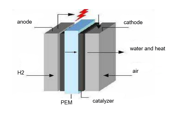
Figure 5. Basic structure of the PEMFC.
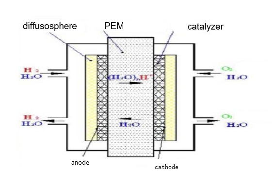
Figure 6. Internal chemical reaction inside PEMFC.
4. Hybrid engines
A hybrid engine is one that uses two or more distinct types of power, for a vehicle which usually combines an electric motor with a battery and an internal combustion engine. The motor can start the vehicle and accelerate independently, which is not just a simple auxiliary device, but is equivalent to having two power engines, commonly used in family cars and city buses. When the car starts, it relies on electricity to reduce emissions. After driving steadily, it can switch to the engine power to provide thrust. There are also types of motors and engines that work at the same time, which are mostly used in racing. For example, the hybrid engine of Formula 1 is dominated by the internal combustion engine, while motors are mostly used in overtaking, qualifying laps and other specific situations which require huge power support.
According to the research conducted by Harbin University of Science and Technology, due to the current 71% coal power generation ratio in China in 2020, compared with internal combustion engine vehicles, hybrid vehicles can reduce carbon dioxide emissions by about 42%. As is shown in the picture below, for a specific car, assuming that the car consumes 6.31 liters of gasoline per hundred kilometers and it runs 10000 kilometers per year, the annual carbon dioxide consumption can be up to 1.626 tons. For the hybrid electric vehicle, it consumes 14 kWh of electric energy per 100 km. Since there is no need to emit carbon dioxide during the operation period, the annual carbon dioxide emission is only 0.95 tons, 42% less than that of traditional internal combustion engine vehicles, which is much more eco-friendly [10]. Figure 7 shows the carbon emissions reduced by the hybrid system.
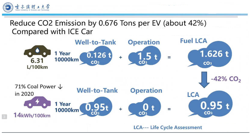
Figure 7. Carbon emission reduced by hybrid system.
For motor racing, every tiny weight loss will increase lap time in the race. The hybrid system can not only reduce the fuel carrying capacity in the race, but also provide additional power at critical moments to enable the car giving better performance. This paper takes the hybrid system of Formula 1 racing car as an example to analyze. The hybrid system of F1 car includes the engine part and the electric motor part. The engine part is the internal combustion engine, while the electric motor part includes energy storage battery, kinetic energy motor MGU-K, internal energy motor MGU-H and central control system MGU control unit, which is referred as MCU in this paper [11]. Figure 8 shows the basic structure of the hybrid system of Formula 1.
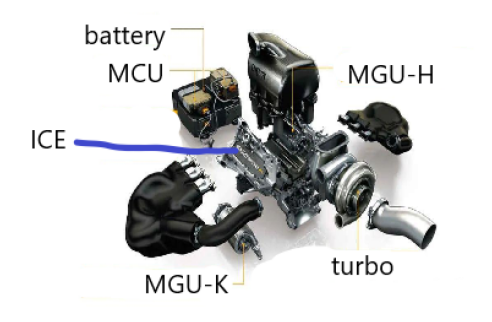
Figure 8. Basic structure of formula 1 hybrid system.
The electric motor modes of racing cars can be roughly divided into three types: qualifying mode, overtaking mode and cruising mode. In overtaking mode, MGU-K has the largest output power. Under the engine rule of 2021, it can output another 180 horsepower by the electric motor. In other words, it can improve the speed trap by 20-30 kilometers per hour at the end of the straight. However, the excessive use of overtaking mode will not only consume a lot of battery power and cause de-rating; the phenomenon which motor does not output any power. Not only will cause a sharp speed drop in straight line, but also make the engine overheated and increase the risk of mechanical failure of the racing car. Therefore, when the overtaking mode is turned on, it is usually a fatal attack, otherwise it will be very difficult to launch another attack in a short time. In qualifying mode, the motor will open the pressure relief valve at the corner exit of the straight to achieve the highest power output, while at the curve and the end of the straight track, the motor will achieve a lower power output. This kind of output power usually consumes all the power within one turn to ensure the speed of one turn. The cruise mode will only input but not output, which can continuously store battery charge. This mode is usually used for the cruise area at the qualifying outlap, curves and the end of straights in the race. These cruise areas are generally set by the team program.
When the car brakes, the brake discs will generate huge heat. This heat has three different kinds of trends. The first part is distributed to the air to reduce the temperature of the brake disc. The second part is absorbed by MGU-H, in which the heat energy is converted into electrical energy through signal transformation and stored in the battery. The third part can be used for tires heating. MCU is the core of the whole motor, which can be regarded as a transmitter and also a controller. During the whole process, MGU-H always captures the internal energy of the brake disc and converts it into electric energy. At this point, it is assumed that the driver has used overtaking mode and the battery power has been reduced. The MCU transmitter captures the signal of the battery charge reduction, and it output a Δe as the D-value. The D-value is transmitted as controller language into MGU-K, which captures the D-value of MCU transmission terminal output, and adjusts the motor mode to cruise mode to store the battery charge. When the battery charge is stored to a certain level and the driver needs to open overtaking mode again, the control terminal of MCU can make MGU-K open the overtaking mode and output more power. When the electric quantity needs to be stored, the cycle will be repeated [12].
5. Conclusion
In a word, after investigating three different types of engines, it is found that as time goes by, how to achieve environmental protection has become the most important problem of automobile engines. With the help of electric energy, the automobile engines have not only become cleaner and more environmentally friendly, but also greatly improved their performance. In addition to hybrid system and fuel cell, cleaner energy will also be used for engines, such as bio-diesel, E10 fuel, etc. Therefore, there is sufficient reason to believe that in the future, there will be no need to worry about the industrial pollution caused by carbon emissions. At that time, mankind will achieve peaceful coexistence with nature genuinely.
References
[1]. Rainer K. 2018 Electric Propulsion in Gliders Is More Than an Alternative to Traditional Combustion Engines. Soaring, 82(2): 24-29.
[2]. Hale J M. 2009 Comparative Analysis of Realtime Game Engines to Traditional Methods of Design Communication. Energy, 20: 109-118.
[3]. Shi Y, Ge H W, Brakora J L. 2010 Automatic Chemistry Mechanism Reduction of Hydrocarbon Fuels for HCCI Engines Based on DRGEP and PCA Methods with Error Control. Energy & Fuels, 24(7): 1646-1654.
[4]. Hwang D, Wontae D. 2020 Fuel Stratification for Low-Load HCCI Combustion: Performance and Fuel-PLIF Measurements. 20: 107-109.
[5]. Peng A. 2007 Study the ethanol SI/HCCI combustion mode transition by using the fast thermal management system. Chinese Science Bulletin, 20: 109-116.
[6]. Kim H, Lee R K. 2007 A study on the characteristics of spray and combustion in a HCCI engine according to various injection angles and timings. Journal of Mechanical Science&Technology, 20: 207-218.
[7]. Bakhshan Y, Tarahomi R. 2011 Multi-Dimensional Simulation of n-Heptane Combustion under HCCI Engine Condition Using Detailed Chemical Kinetics. The Journal of Engine Research, 11(22): 78-85.
[8]. Liu H, Zheng Z, Zhang B. 2009 Influence of fuel characteristics on combustion and operating range of HCCI engine. Journal of Internal Combustion Engine, 27 (3): 9.
[9]. Zhang Q, Zheng C, He Z. 2011 A simplified chemical kinetics model of toluene reference fuel for HCCI combustion research. Journal of Physical Chemistry, 20: 110-118.
[10]. Wang Y, Zhou L B, Jiang D M. 2002 Research Development and Main Challenge of Homogeneous Charge Compression Ignition(HCCI). Vehicle Engine, 20: 302-308.
[11]. Zhao W, Zhang C, Tong J. 2012 Effect of EGR on combustion and emission of methanol HCCI engine. Journal of Chang'an University: Natural Science Edition, 32(4): 5.
[12]. Zhou N, Xie H, Zhao H. 2009 Development of real-time control system for gasoline HCCI engine. China Mechanical Engineering, 7(8): 5-17.
Cite this article
Gao,F.;Jin,Q.;Zhao,T. (2023). Performance comparison between traditional engines and various alternative engines. Applied and Computational Engineering,3,195-203.
Data availability
The datasets used and/or analyzed during the current study will be available from the authors upon reasonable request.
Disclaimer/Publisher's Note
The statements, opinions and data contained in all publications are solely those of the individual author(s) and contributor(s) and not of EWA Publishing and/or the editor(s). EWA Publishing and/or the editor(s) disclaim responsibility for any injury to people or property resulting from any ideas, methods, instructions or products referred to in the content.
About volume
Volume title: Proceedings of the 3rd International Conference on Materials Chemistry and Environmental Engineering (CONF-MCEE 2023)
© 2024 by the author(s). Licensee EWA Publishing, Oxford, UK. This article is an open access article distributed under the terms and
conditions of the Creative Commons Attribution (CC BY) license. Authors who
publish this series agree to the following terms:
1. Authors retain copyright and grant the series right of first publication with the work simultaneously licensed under a Creative Commons
Attribution License that allows others to share the work with an acknowledgment of the work's authorship and initial publication in this
series.
2. Authors are able to enter into separate, additional contractual arrangements for the non-exclusive distribution of the series's published
version of the work (e.g., post it to an institutional repository or publish it in a book), with an acknowledgment of its initial
publication in this series.
3. Authors are permitted and encouraged to post their work online (e.g., in institutional repositories or on their website) prior to and
during the submission process, as it can lead to productive exchanges, as well as earlier and greater citation of published work (See
Open access policy for details).
References
[1]. Rainer K. 2018 Electric Propulsion in Gliders Is More Than an Alternative to Traditional Combustion Engines. Soaring, 82(2): 24-29.
[2]. Hale J M. 2009 Comparative Analysis of Realtime Game Engines to Traditional Methods of Design Communication. Energy, 20: 109-118.
[3]. Shi Y, Ge H W, Brakora J L. 2010 Automatic Chemistry Mechanism Reduction of Hydrocarbon Fuels for HCCI Engines Based on DRGEP and PCA Methods with Error Control. Energy & Fuels, 24(7): 1646-1654.
[4]. Hwang D, Wontae D. 2020 Fuel Stratification for Low-Load HCCI Combustion: Performance and Fuel-PLIF Measurements. 20: 107-109.
[5]. Peng A. 2007 Study the ethanol SI/HCCI combustion mode transition by using the fast thermal management system. Chinese Science Bulletin, 20: 109-116.
[6]. Kim H, Lee R K. 2007 A study on the characteristics of spray and combustion in a HCCI engine according to various injection angles and timings. Journal of Mechanical Science&Technology, 20: 207-218.
[7]. Bakhshan Y, Tarahomi R. 2011 Multi-Dimensional Simulation of n-Heptane Combustion under HCCI Engine Condition Using Detailed Chemical Kinetics. The Journal of Engine Research, 11(22): 78-85.
[8]. Liu H, Zheng Z, Zhang B. 2009 Influence of fuel characteristics on combustion and operating range of HCCI engine. Journal of Internal Combustion Engine, 27 (3): 9.
[9]. Zhang Q, Zheng C, He Z. 2011 A simplified chemical kinetics model of toluene reference fuel for HCCI combustion research. Journal of Physical Chemistry, 20: 110-118.
[10]. Wang Y, Zhou L B, Jiang D M. 2002 Research Development and Main Challenge of Homogeneous Charge Compression Ignition(HCCI). Vehicle Engine, 20: 302-308.
[11]. Zhao W, Zhang C, Tong J. 2012 Effect of EGR on combustion and emission of methanol HCCI engine. Journal of Chang'an University: Natural Science Edition, 32(4): 5.
[12]. Zhou N, Xie H, Zhao H. 2009 Development of real-time control system for gasoline HCCI engine. China Mechanical Engineering, 7(8): 5-17.