


1. Introduction
With the continuous advancement of the economy, urban infrastructure construction plays an increasingly pivotal role in urban development. The presence of wide streets and efficient traffic has also become a crucial criterion for assessing a city's level of development. However, simultaneously, there is a growing number of cars on the roads, leading to corresponding traffic issues that hinder the progress of many cities [1, 2]. To address and alleviate these problems, three general approaches are commonly adopted: firstly, enhancing the quality of urban infrastructure by constructing new viaducts, subways, and widening roads; secondly, implementing intelligent transportation systems; thirdly, promoting public transport usage while imposing restrictions on private car license plates [3]. The first approach entails significant costs and time consumption. The third method restricts citizens travel options to some extent. On the other hand, the second approach boasts low costs and has been successfully experimented with in Europe and the United States as evidenced by favorable outcomes from available data.
The traffic control system discussed in this paper falls under the second approach category. By utilizing FPGA technology effectively, traffic lights can possess basic intelligence capabilities that significantly alleviate congestion issues. This paper is mainly divided into the following three parts--The second chapter is the theoretical basis and system design of traffic signal control system, including FPGA technology and system framework design. The third chapter discusses the design of the hardware. This chapter analyzes the overall design of hardware, introduces the main chip of FPGA, and analyzes and designs the circuit of each unit of the system. Including Power module, clock module, power filter circuit, key circuit, traffic light circuit and seven-segment digital tube circuit. The fourth chapter is the software design and simulation of the system. Based on the system operation scheme of the system, this chapter mainly develops the environment through Quartus II integrated development, uses Verilog language to program each module of the traffic signal controller, and simulates it. Finally, according to the simulation results, the article analyzes whether the program can realize the operation requirements of the traffic light controller [4].
2. Theoretical foundation and comprehensive design framework
2.1. FPGA Technology
FPGA, or Field-Programmable Gate Array, is a type of integrated circuit that allows users to configure its internal hardware after manufacturing. Unlike traditional fixed-function chips, FPGAs are highly flexible and can be programmed to perform a variety of tasks.
The history of FPGA development reflects its evolution from simple programmable logic devices to advanced, highly capable hardware components. The concept of programmable logic began with simple programmable logic devices (PLDs) in the 1980s. Early devices were limited in size and functionality, used primarily for basic logic functions. With the introduction of Xilinx's XC4000 series in 1991, FPGA started to gain significant attention [5]. During that time, there was a substantial improvement in programmable core fabrication technology. For instance, the XC4003 utilized 0.7μm technology and incorporated 440,000 crystalline tubes. Hardware developers gradually began to recognize the potential of programmable tools as effective resources for circuit opening and testing. Subsequently, with advancements in digital signal processing technology, high-speed string receivers and transmitters, as well as embedded processing devices, FPGA progressively captured the interest of a wider audience - emerging as a rapidly developing star within the semiconductor industry.
FPGA has quite a few advantages. The most important advantage is reconfigurability [6]. FPGAs can be reprogrammed to implement different logic functions or adapt to changing requirements. This flexibility allows for rapid prototyping and iterative design changes without needing new hardware. The traffic light control discussed in this article also emphasizes the significance of this aspect, as the operation of traffic lights may undergo changes with urban expansion. By leveraging FPGA technology, adjustments to traffic light settings can be promptly implemented without necessitating new hardware purchases.
2.2. Design and framework of the controller system
Due to the author's limited expertise, this paper only considers the most basic case of intersection, specifically focusing on traffic lights for straight movement and excluding those for left and right turns. This simplification greatly facilitates problem-solving. Additionally, it is important to note that the intersection comprises a main road and a branch road. However, it should be emphasized that the traffic light control system employed here differs from conventional ones as special circumstances have been fully taken into account during its design process. Include these conditions: 1. No car on the main road or branch road. 2.There is an emergency on the main road or branch road. 3.The main road is in rush hour. 4.Without special circumstances. The framework of the system is shown in the Figure 1.
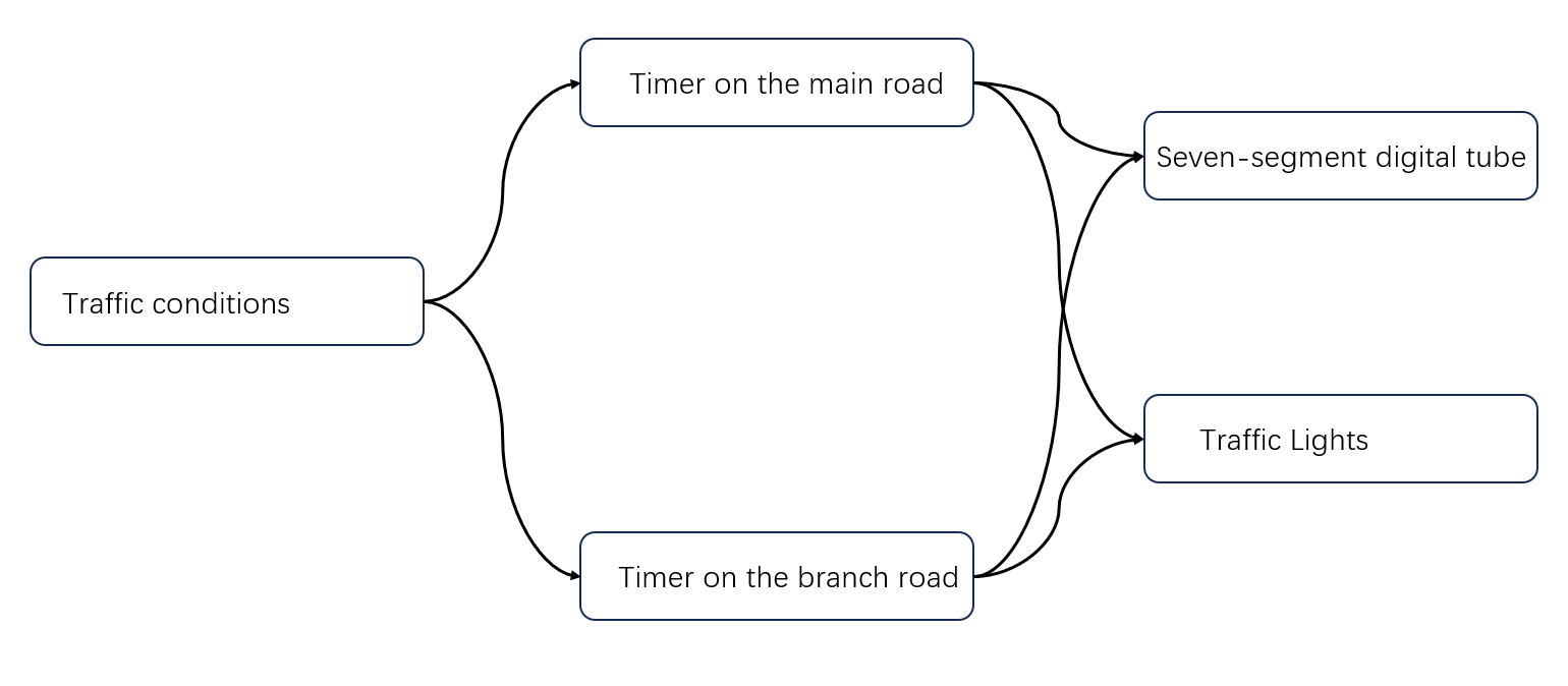
Figure 1: The framework of the system
As shown in the figure 1, the overall design framework of the system can be clearly seen. The LED stands for traffic light. The system is designed in accordance with specific traffic conditions—the first is that there are cars on the main road, and also on the side road. As a result, the traffic light on the main road will keep green for 30 seconds, the traffic light on the branch road will keep green for 20 seconds, and there is a yellow light for 5 seconds after the green light ends. The second is that there is no car on the main road or side road, so at this time, the green light will be maintained on the other road with cars. The third is that there is an emergency on the main road or branch road. If there is an emergency on the main road, the traffic lights on the main road will remain green. On the contrary, if there is an emergency on the branch road, the traffic lights on the branch road will remain green. Finally, when the main road is in rush hour, the main road will have 90 seconds of green light, and the branch road will only have 15 seconds of green light.
The traffic light controller system based on FPGA consists of the main control module, power module, clock module, program download module, traffic light module, key input module, and a seven-segment digital tube. Each module operates in synchronization under the supervision of the main controller. The system framework diagram is depicted in the figure 2.
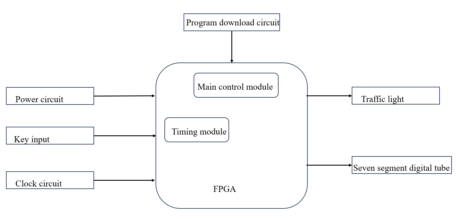
Figure 2: The framework of the system
After the power supply circuit energizes the entire control system, the clock circuit generates a stable clock signal for system synchronization. The software development process of the system is carried out in Quartus II using programming language, and the program is subsequently downloaded to the chip. By utilizing the key circuit, traffic conditions can be selected to effectively control both traffic lights and code tubes. The design of the system based on FPGA has been successfully accomplished in this manner.
3. Hardware design of traffic light controller system
3.1. The overall design of the hardware
The system, being a typical traffic light controller, imposes stringent requirements on power consumption, size, and reliability. The hardware design of the FPGA-based traffic light controller primarily encompasses core device selection, configuration chip design, and configuration circuitry. The hardware structure of the system is depicted in the Figure 3.
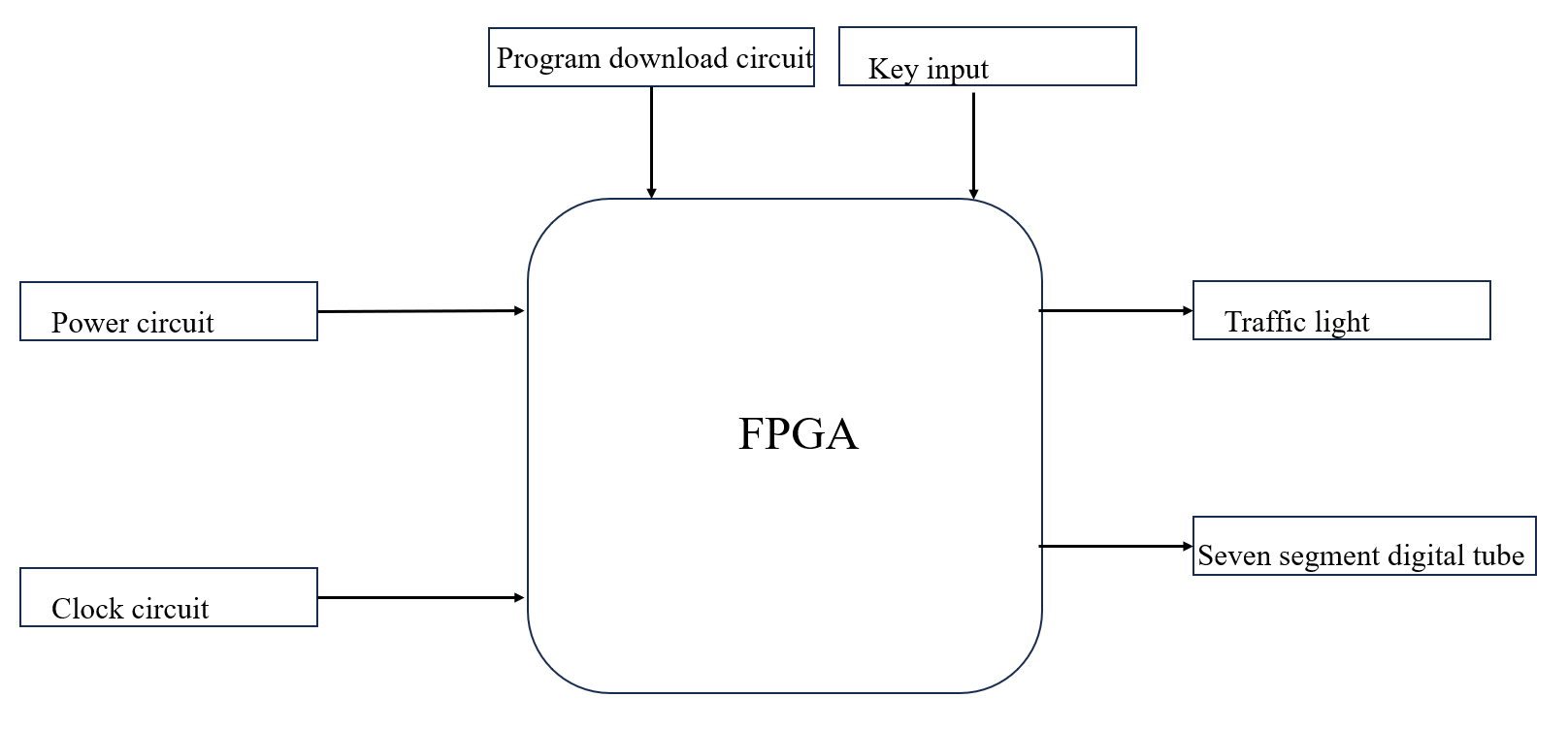
Figure 3: The hardware structure of the system
The core device is Cyclone II series FPGA produced by Altera, and its key technology is to realize the design of configurable and tailorable system on Quartus II and Nios IDE platforms [7]. The power supply circuit is to supply the power needed for the whole control system. The clock circuit provides stable clock signal for FPGA controller and timing module, and completes the system control, calculation and normal operation of the module. The main function of the key input circuit is to power up and restore, low level has effect, and press the key to reset the system; The second is the work selection, by pressing the key to select the specific traffic conditions. The traffic light and seven segment digital tube are the display parts of the circuit, and the light on and off is controlled according to the control signal number of the inner control module, so does the time display of the digital tube.
3.2. Analysis of the main chip
The FPGA core chip utilized in the system is the Cyclone II series chip manufactured by Altera, with EP2C35F484C8N as its specific model. This chip boasts compact size and robust performance [8]. Cyclone II FPGAs offer 60% higher performance and half the power consumption of competing 90-nm FPGAs [9]. The cost-effectiveness and optimized feature set of Cyclone II FPGAs render them an ideal solution for the system.
3.3. The design of the modular circuit
3.3.1. Power module
The hardware system requires a power supply for proper functioning in every component. This paper proposes the utilization of a 5V input power supply, with voltage conversion being achieved through the use of a regulator chip to meet the different operating voltages required by other chips. As the main control chip FPGA operates at 3.3V, an LM1804 voltage regulator chip can be employed to convert the 5V input voltage into the required 3.3V [10]. Figure 4 displays the circuit.
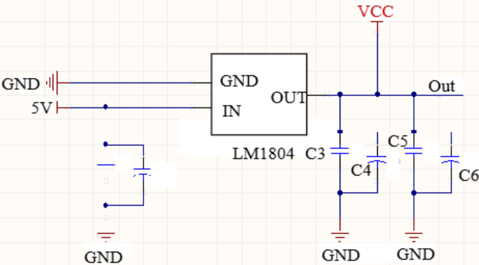
Figure 4: The circuit of the power module
3.3.2. Clock circuit
The system utilizes an active crystal oscillator to generate a stable frequency of 50MHz [11]. The clock pin of the FPGA is directly connected to the output signal of the active crystal oscillator, ensuring a reliable and convenient frequency generation solution. Considering that the I/O pin voltage of the FPGA chip operates at 3.3V, we have opted for an active crystal oscillator powered by 3.3V, as shown in the Figure 5.
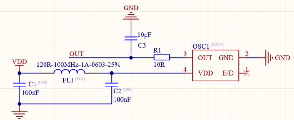
Figure 5: The circuit of the clock module
3.3.3. Power filter circuit
The power filter circuit significantly enhances circuit stability by employing 10μF and 0.1μF capacitors between the 5V, 3V, and 1.2V power supplies and ground to eliminate interference [12]. Larger capacitance effectively filters low-frequency signals, while smaller capacitance efficiently filters high-frequency signals. Figure 6 shows the circuit.
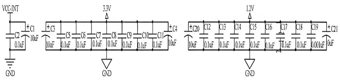
Figure 6: The circuit of the power filter
3.3.4. Key circuit
The key input circuit is essential to the system. Firstly, FPGA is a typical digital logic circuit that imposes high demands on the entire system. Even slight phase deviations exhibited by any module or chip within the circuit can lead to faults in the operation of the entire system. Disconnecting the power source directly may cause damage to component elements as they need to be restored for proper functioning. Secondly, the key circuit directly influences traffic condition selection. As mentioned earlier, different traffic conditions are determined by the key circuit; therefore, only a well-designed key circuit system can ensure normal operation and facilitate smooth traffic condition conversion. This system utilizes a low-level reset mechanism where pressing a specific button triggers it, as illustrated in Figure 7.
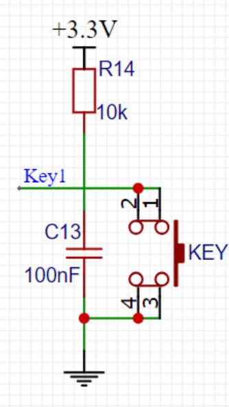
Figure 7: Key circuit
3.3.5. Traffic light circuit
The traffic light system comprises two main directions. When one side of the traffic light displays green or yellow, the other side shows red. During this process, the duration of green signal for each road is determined by different traffic conditions, which are in turn influenced by the key circuit in the preceding section. In this paper, the traffic light is directly controlled by FPGA, which ensures smooth flow of vehicles. The specific circuit is illustrated in Figure 8.
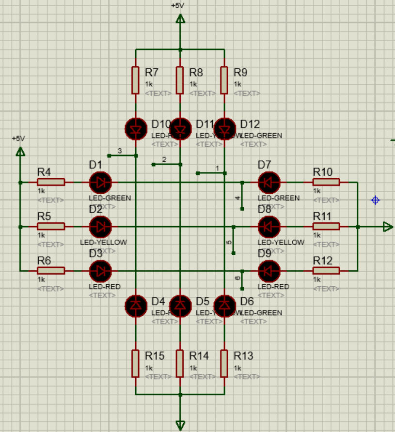
Figure 8: The circuit of the traffic light
3.3.6. Seven-segment digital display circuit
The seven-segment digital display is utilized for presenting the countdown of the traffic light within this system. In this study, a common anode configuration is employed, wherein the common terminal of all seven light-emitting segments is connected to VCC. Simultaneously, the digital display is linked to the FPGA's I/O interface, enabling control over which digital display illuminates and the display content of the digital display. Figure 9 illustrates the circuit.
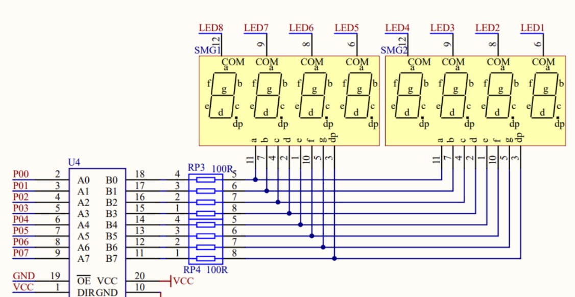
Figure 9: The circuit of the seven-segment digital tube
4. Tables Software design and simulation of traffic light controller system
4.1. Design of timing control scheme
The duration of traffic lights in this system will be adjusted based on varying traffic conditions. There are four different scenarios: 1. No car on the main road or branch road--the traffic lights will stay red on the road without cars. 2. There is an emergency on the main road or branch road-- the traffic lights will stay green on the road with emergency. 3. The main road is in rush hour-- The traffic lights on the main road display a green signal for a duration of 90 seconds, followed by a red signal for 15 seconds. 4. Without special circumstances—the time of green light on the main road is 30 seconds, and it is 20 seconds on the side road.
The green light is followed by a yellow light for a duration of 5 seconds in all of the aforementioned scenarios. The definition of input signal is shown in the Figure 10.
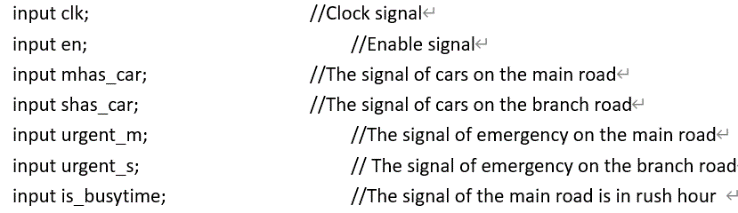
Figure 10: The definition of the input
4.1.1. State machine transition logic
The state machine transition logic is the most basic part of the program, which determines how the traffic lights change. To begin with, we first need to define the state. There are four different states. The first state is S1, in which the main road light is green and the branch road one is red. After that, during State 2, the main road light turns yellow and the branch road one remains red. Then the color of the main and branch road lights turns to red and green in S3 and red and yellow in S4, respectively.
Because the conversion of s3 and s4 is similar to that of s1 and s2, we will only carefully describe that of s1 and s2. As showed in the picture 10, the state can change in order or remain stable according to the input signal which include urgent_m, urgent_s, mhas_car==0&&shas_car==1, shas_car==1&&mcount==0 and so on. The conversion of four states is shown in the Figure 11.
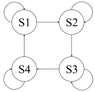
Figure 11: The conversion of four states
During the state S1, if the urgent_m is 1, the state doesn’t change. But if the urgent_s is 1, the state will change to S2, which means there are urgent conditions in the branch road. When the mhas_car signal is 0 and the shas_car signal is 1, which means there are cars on the branch road and no car on the main road, the state change to S2. Significantly, if there are no special signals, the state will remain the same. However, if the mcount=0, which means the time of state is exhausted, the state will change to S2. As for the output, m_yellow_flag changes to 1 if the state changes to S2. The counter of the red light in the side street has a five-second delay, indicating that it corresponds to the duration of the yellow light interval.
It is much simpler when it comes to S2. As the Figure 11 shows, before the five seconds yellow time is finished. The mcount isn’t 0, and the state remains S2. When the yellow time is finished, the mcount changes to 0 and the state changes to the S3. Meanwhile, the m_yellow_flag changes to 0, and the s_flag changes to 1. The transition is displayed in the Figure 12.
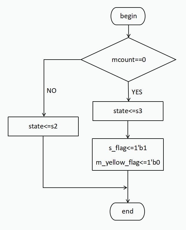
Figure 12: The transition of four states
4.1.2. The counter module
The counter module is a traffic light controller implemented with a state machine. It manages the timing of green, yellow, and red lights for both the main and side roads at an intersection. The discussion in this article will focus on state 1 and state 2 due to their similarity with state 3 and state 4. The program begins by resetting the system when the enable signal (en) is low, initializing the main road (mcount) and side road (scount) timers based on whether it is in rush hour (is_busytime). In normal operation, the program switches between four states: S1 (Main Road Green), S2 (Main Road Yellow), S3 (Side Road Green), and S4 (Side Road Yellow). In S1, the traffic light on the main road is green, while the side road waits with a red light. If there's an emergency on the main road (urgent_m), the program resets the timers. If there's an emergency on the side road (urgent_s), the main road transitions to yellow (S2). The system continuously checks whether vehicles are present on the roads (mhas_car, shas_car) and dynamically adjusts the light duration. Similarly, in S3, the side road has a green light, and the program transitions between S3 and S4 (side road yellow) based on the same emergency and vehicle conditions. The counters control the timing, and after each yellow light state (S2 and S4), the timers are reset to prepare for the next cycle.
The way of countdown in the Verilog traffic light controller is managed using two counters: mcount for the main road and scount for the side road. Additionally, a secondary counter, cnt, is used to count up to a predefined value MCNT, which represents one second. During each state, such as S1 (main road green light) or S3 (side road green light), cnt increments until it reaches MCNT. Once cnt hits this threshold, it resets to zero and decrements either mcount (for the main road) or scount (for the side road), depending on which road has the active green light. This process repeats until mcount or scount reaches zero, signaling the transition to the next state, such as switching to a yellow light or changing which road has the green light. The picture below shows a flowchart for state 2. It represents that in state 2, different value will be given to the countdown. The flowchart for the state 2 is shown in the Figure 13.
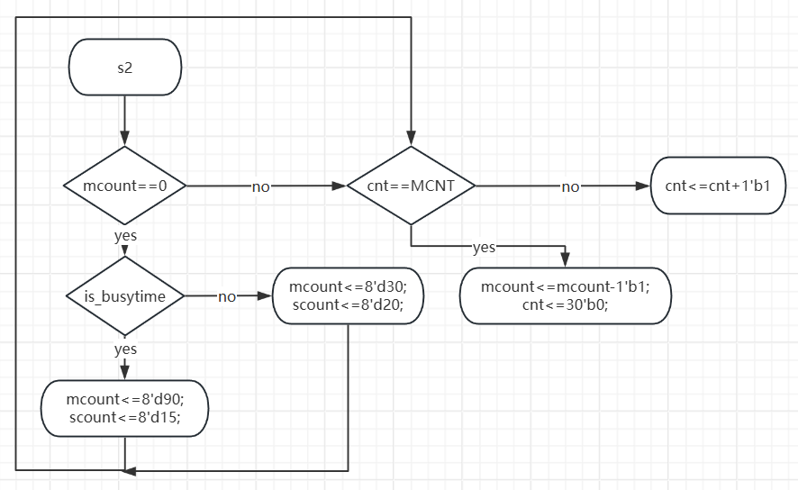
Figure 13: The flowchart for the state 2
4.1.3. The traffic light module
This part is mainly to control the display of traffic lights. The traffic lights simply need to be correlated with distinct states.
In the S1 state, the light on the main road is green, and the light on the side road is red. Similarly, in the S2 state, the main road is yellow, and the side road is red. In the S3 state, the main road is red, and the side road is green. In the S4 state, the main road is red, and the side road is yellow.
4.2. Simulation and verification
In the program, mcount is a signal of the remaining time of the main road light. During the rush hour, mcount can reach a maximum value of 90 seconds. As shown in the Figure 14, mcounter changes from the maximum value of 90 in the simulation. Specifically, the signal mt_2 shows the digit number of mcount, and mt_1 shows the individual digit number of mcount. In the final simulation, mcount decrease one after every two clock periods, which achieves its goal perfectly. The simulation of the mcounter is shown in the Figure 14.
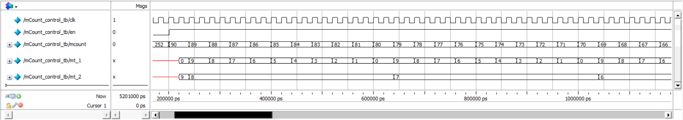

Figure 14: Mcounter_control
Scount is similar to mcount and the Figure 15 shows its change from maximum value of 20.
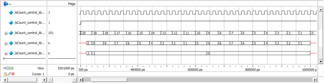
Figure 15: Scount_control
Seven-segment display is used to show the countdown numbers on traffic lights. Specifically, the segment can show the number from 0 to 9 with the output signal SG_out, which depends on the imput signal called DATA_in. The conversion of signals is showed in Figure 16.
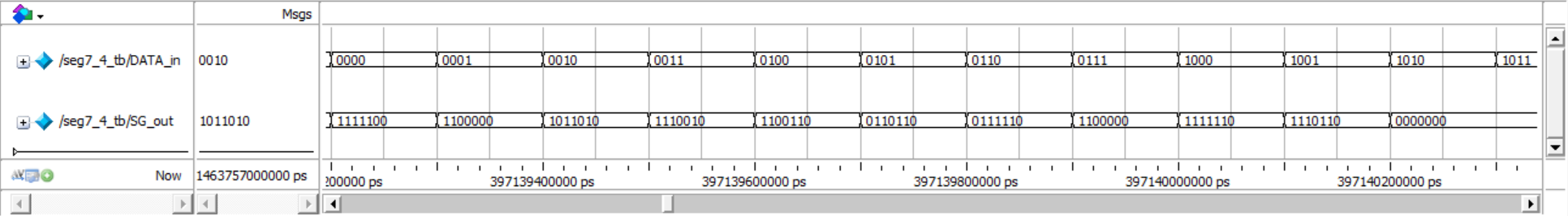

Figure 16: Seven-segment display
During the final test, the traffic light perfectly achieves the goal. Firstly, the main road light is red because m[2] is 1 and it will change to green after 12 seconds because mcount is 12. After that, the m[0] changes to 1, which means the main road light changes to green and mcount changes to 90. As a result, the green light will last for 90 seconds. Moreover, the logic of the side road light design is similar to that of main road light, which is showed in the Figure 17.
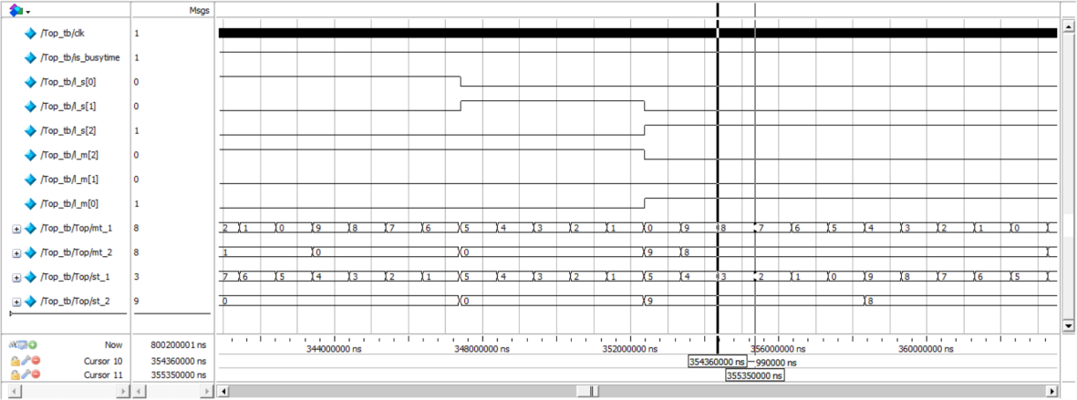
Figure 17: Final light test
If some specific signals change, to fit in the new situation, the duration of traffic light will also change. For example, if the mhas_can changes from 1 to 0, which means the car on the main road all go through the cross. After that, the mcount will changes to five. The main road signal will transition from green to yellow. After a duration of 5 seconds, the countdown will reach zero and the signal will change to red. The simulation of this scenario has been tested and the results are presented in Figure 18.
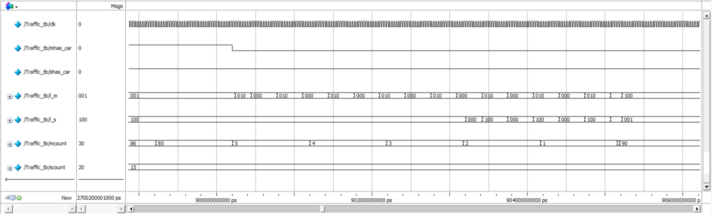
Figure 18: Specific signal change
5. Conclusion
The paper studies and designs the traffic light controller system based on FPGA, taking into account various scenarios such as main road or branch road situations, emergency states, and peak periods. The traffic light controller system is divided into a top-level module and three sub-modules, namely the state machine module, timer module, and traffic light module, in terms of overall design. This thesis primarily accomplishes the following four aspects.
1. Introducing the technical background and development history of FPGA while emphasizing the significance of FPGA technology for this system. 2. Completing core chip selection and peripheral circuit design by combining key parameters and selection principles to choose suitable chips. Additionally, summarizing chip characteristics and designing FPGA peripheral circuits, signal control circuits, and power supply circuits for these chips. 3. Realizing modular program design for the entire system based on hardware functional requirements. Designing top-level modules and clock modules, state machine conversion modules, timer modules, and traffic light control modules within the FPGA main control chip. 4. The simulation of each module has been implemented. In this paper, Quartus II is utilized to conduct functional and timing simulations for the top-level module, state machine conversion module, timer module, and traffic light control module based on the content of the module design. Additionally, a detailed analysis of the simulation waveforms for these modules is performed to validate the program design accuracy.
References
[1]. Patriksson M. The traffic assignment problem: models and methods. Courier Dover Publications, 2015.
[2]. Field-programmable gate array technology. Springer Science & Business Media, 2012.
[3]. Cao Z, Jiang S, Zhang J, et al. A unified framework for vehicle rerouting and traffic light control to reduce traffic congestion. IEEE transactions on intelligent transportation systems, 2016, 18(7): 1958-1973.
[4]. Hamblen J O, Hall T S, Furman M D. Rapid Prototyping of Digital Systems: Quartus® II Edition. Springer Science & Business Media, 2006.
[5]. Rodríguez-Andina J J , Valdes-Pena M D, Moure M J. Advanced features and industrial applications of FPGAs—A review. IEEE Transactions on Industrial Informatics, 2015, 11(4): 853-864.
[6]. Mencer O, Allison D, Blatt E, et al. The History, Status, and Future of FPGAs: Hitting a nerve with field-programmable gate arrays. Queue, 2020, 18(3): 71-82.
[7]. Joshi N N, Dakhole P K, Zode P P. Embedded web server on Nios II embedded FPGA platform. 2009 Second International Conference on Emerging Trends in Engineering & Technology. IEEE, 2009: 372-377.
[8]. Ito H, Watanabe M. Total ionizing dose tolerance of the serial configuration on cyclone II FPGA. 2015 IEEE International Conference on Space Optical Systems and Applications (ICSOS). IEEE, 2015: 1-4.
[9]. Wong H, Betz V, Rose J. Comparing FPGA vs. custom CMOS and the impact on processor microarchitecture. Proceedings of the 19th ACM/SIGDA international symposium on Field programmable gate arrays. 2011: 5-14.
[10]. Lu Y Y, Chen K K, Chen P Y, et al. The implementation of driving anti-sleep safety warning system. 18th Int. Symp. Artificial Life and Robotics (AROB) Conf. Location Daejeon, South Korea. ALIFE ROBOTICS CO, LTD Location SHIMOHANDA, 2013: 238-241.
[11]. Frerking M. Crystal oscillator design and temperature compensation. Springer Science & Business Media, 2012.
[12]. Tang Y, Loh P C, Wang P, et al. Generalized design of high performance shunt active power filter with output LCL filter. IEEE Transactions on industrial Electronics, 2011, 59(3): 1443-1452.
Cite this article
Cao,K. (2025). Traffic Light Controller System Analysis Based on FPGA. Applied and Computational Engineering,124,199-211.
Data availability
The datasets used and/or analyzed during the current study will be available from the authors upon reasonable request.
Disclaimer/Publisher's Note
The statements, opinions and data contained in all publications are solely those of the individual author(s) and contributor(s) and not of EWA Publishing and/or the editor(s). EWA Publishing and/or the editor(s) disclaim responsibility for any injury to people or property resulting from any ideas, methods, instructions or products referred to in the content.
About volume
Volume title: Proceedings of the 5th International Conference on Materials Chemistry and Environmental Engineering
© 2024 by the author(s). Licensee EWA Publishing, Oxford, UK. This article is an open access article distributed under the terms and
conditions of the Creative Commons Attribution (CC BY) license. Authors who
publish this series agree to the following terms:
1. Authors retain copyright and grant the series right of first publication with the work simultaneously licensed under a Creative Commons
Attribution License that allows others to share the work with an acknowledgment of the work's authorship and initial publication in this
series.
2. Authors are able to enter into separate, additional contractual arrangements for the non-exclusive distribution of the series's published
version of the work (e.g., post it to an institutional repository or publish it in a book), with an acknowledgment of its initial
publication in this series.
3. Authors are permitted and encouraged to post their work online (e.g., in institutional repositories or on their website) prior to and
during the submission process, as it can lead to productive exchanges, as well as earlier and greater citation of published work (See
Open access policy for details).
References
[1]. Patriksson M. The traffic assignment problem: models and methods. Courier Dover Publications, 2015.
[2]. Field-programmable gate array technology. Springer Science & Business Media, 2012.
[3]. Cao Z, Jiang S, Zhang J, et al. A unified framework for vehicle rerouting and traffic light control to reduce traffic congestion. IEEE transactions on intelligent transportation systems, 2016, 18(7): 1958-1973.
[4]. Hamblen J O, Hall T S, Furman M D. Rapid Prototyping of Digital Systems: Quartus® II Edition. Springer Science & Business Media, 2006.
[5]. Rodríguez-Andina J J , Valdes-Pena M D, Moure M J. Advanced features and industrial applications of FPGAs—A review. IEEE Transactions on Industrial Informatics, 2015, 11(4): 853-864.
[6]. Mencer O, Allison D, Blatt E, et al. The History, Status, and Future of FPGAs: Hitting a nerve with field-programmable gate arrays. Queue, 2020, 18(3): 71-82.
[7]. Joshi N N, Dakhole P K, Zode P P. Embedded web server on Nios II embedded FPGA platform. 2009 Second International Conference on Emerging Trends in Engineering & Technology. IEEE, 2009: 372-377.
[8]. Ito H, Watanabe M. Total ionizing dose tolerance of the serial configuration on cyclone II FPGA. 2015 IEEE International Conference on Space Optical Systems and Applications (ICSOS). IEEE, 2015: 1-4.
[9]. Wong H, Betz V, Rose J. Comparing FPGA vs. custom CMOS and the impact on processor microarchitecture. Proceedings of the 19th ACM/SIGDA international symposium on Field programmable gate arrays. 2011: 5-14.
[10]. Lu Y Y, Chen K K, Chen P Y, et al. The implementation of driving anti-sleep safety warning system. 18th Int. Symp. Artificial Life and Robotics (AROB) Conf. Location Daejeon, South Korea. ALIFE ROBOTICS CO, LTD Location SHIMOHANDA, 2013: 238-241.
[11]. Frerking M. Crystal oscillator design and temperature compensation. Springer Science & Business Media, 2012.
[12]. Tang Y, Loh P C, Wang P, et al. Generalized design of high performance shunt active power filter with output LCL filter. IEEE Transactions on industrial Electronics, 2011, 59(3): 1443-1452.