


1. Instruction
Aerofoil is a key concept in aeronautical engineering. An airfoil is a shaped surface which aims to generate a specific response from the air it traverses. [1]. As the wing's contour and angle of attack are altered, the forces of lift and drag acting on the wing are correspondingly changed. The configuration of a wing's cross-sectional profile dictates how the aerodynamic forces interact with the wing's angle of attack, ultimately shaping the wing's performance. [2]. An appropriately designed airfoil can enhance the aircraft's efficiency by significantly reducing resistance and increasing lift force during flight. Therefore, the selection of aerofoils is of great significance in aeronautical engineering. The NACA airfoil series is introduced by the National Advisory Committee for Aeronautics (NACA) in the mid-1900s. It is a collection of time-honoured airfoil shapes famous for their straightforward design principles and parameterisation. Some of these airfoils have had all the makings of a classic in both academic studies and practical engineering applications. [3]. Among many NACA aerofoils, NACA2412 and NACA0012 have been widely studied and applied for their good aerodynamic performance. Specifically, the NACA2412 aerofoil exhibits good lift at a small Angle of attack and is commonly used in light aircraft and drones; The symmetrical aerofoil of the NACA0012 is suitable for smooth flight, performing well at low speeds, and is used with some small gliders and drones.
Computational Fluid Dynamics (CFD) simulation is becoming a crucial component within the realms of aerodynamics and fluid mechanics. [4]. Therefore, the CFD study of the above two aerofoils can deeply reveal the changes in their aerodynamic characteristics under various flight conditions and provide references for the subsequent aircraft design and improvement.
The study of aerodynamic characteristics of different aerofoils, especially combined with numerical simulation and experimental methods, can provide a scientific basis and data support for aerofoil optimization. With the rapid development of modern Computational Fluid Dynamics (CFD), the aerodynamic characteristics of the aerofoil can be deeply studied using numerical analysis, so that the performance of the aerofoil can be evaluated comprehensively at the design stage. However, there are few studies on systematic comparison of these two types of aerofoil. Thus the aerodynamic characteristics and the specific performance of these two types of aerofoil under different attack angles are analysed and compared in this paper based on ANSYS Fluent fluid simulation software. This result will guide different types of existing aircraft in the design stage and provide theoretical references for the development and testing of new aerofoils.
2. Model simulation
2.1. Geometric models and computational domains
By obtaining Aerofoil coordinates from the Aerofoil Tools database and importing them into Fluent, the geometry for CFD simulation is created. The geometry of NACA2412 and NACA0012 is shown in Figure 1 and Figure 2. Figure 3 shows the calculation domain applied to the simulation. The speed and pressure are specified in the inlet and outlet sections.
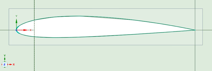
Figure 1: NACA2412 model
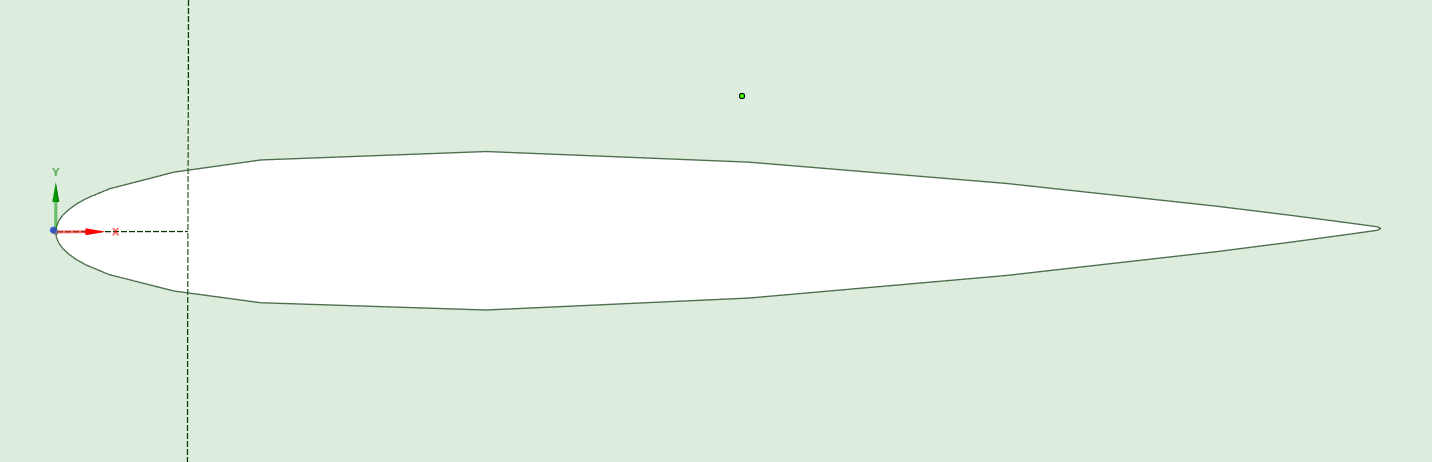
Figure 2: NACA0012 model
The figure below illustrates the geometric shape of the calculation domain. The diameter of the semicircular section and the length of the rectangular section is 15 meters. An airfoil, featuring a chord length of 1 meter, is positioned within this area such that the trailing edge aligns with the midpoint of the semicircular region's diameter while its string line aligns with symmetrical lines of the whole region. The velocity of inlet flow is 33 m/s boundary condition and it is applied to incoming flow. Similarly, exit boundary conditions apply to outflows. Wall conditions apply to the rest of the boundaries. For this research, it is presupposed that the turbulence intensity at the inlet is considerably lower compared to the outlet, hence the turbulence at the velocity inlet boundary is set to 0.1%.
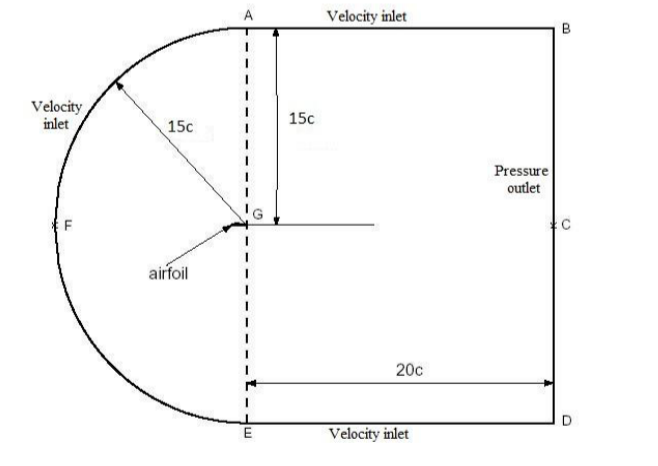
Figure 3: Computational domains
2.2. Grid Division
The quality of meshing will directly affect the reliability of numerical data. Therefore, the 2D structured mesh is selected to generate the grid for the aerofoil and computation domain. To better simulate the flow field motion, the "C" type computation domain is used in the computation domain, and the computation domain is divided into 6 subdomains. To optimize computing efficiency and reduce computing cost, the outer domain adopts coarser cell side lengths for grid processing. A fine mesh is used around the aerofoil to better reflect the airflow movement. The overall grid division at the calculation domain is shown in Figure 4. The details around the aerofoil are shown in Figure 5.
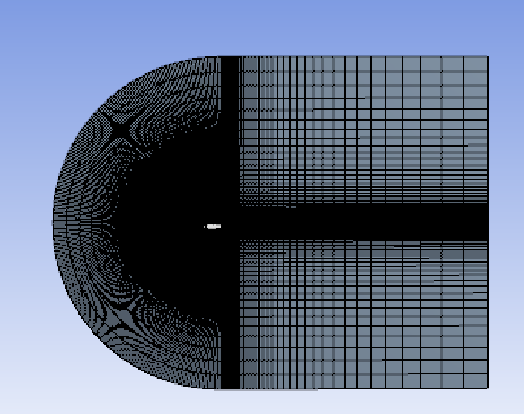
Figure 4: Overall mesh
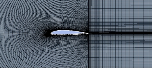
Figure 5: Details of aerofoil mesh
2.3. Boundary conditions and governing equations
Boundary conditions refer to the characteristic physical properties or conditions on the surface of a region that represent a specific flow variable of a physical model [5]. To obtain accurate numerical results, this paper sets 1000 iterations and 10*6 iteration errors during CFD simulation to ensure the convergence of results. Detailed parameters are shown in table 1 below.
Table 1: Boundary condition
General | Solver Time | Pressure-Based Steady |
Turbulence model | Viscous Model | Spalart Almaras |
Material: Air | Density | 1.225kg/m³ |
Boundary conditions | Velocity-Inlet | 33m/s |
Solution methods | Scheme | Coupled |
Pressure | Second Order | |
Momentum | Second Order Upwind | |
Turbulent Kinetic Energy | Second Order Upwind | |
Solution Initialization | Hybrid initialization | |
Run Calculation | Number of Iterations | 1000 |
The turbulence model provides a mathematical framework for predicting how turbulence influences aerofoils. The Spalart-Allmaras model (1992) is a straightforward, single-equation approach that addresses the transport equation for kinematic eddy (turbulent) viscosity. Tailored for aerospace applications, particularly those with wall-bounded flows, it has demonstrated reliable performance in scenarios involving boundary layers under adverse pressure gradients [6].
The basic governing equations used in this paper are given below:
The continuity equation is expressed as follows:
\( \frac{∂ρ}{∂t}+∇\cdot (ρ\vec{V})=0 \) (1)
Navier-Strokes is expressed as follows:
\( \frac{∂}{∂t}(ρ\vec{V})+∇\cdot (ρ\vec{V}\vec{V})=-∇p+∇\cdot (\bar{\bar{r}})+ρ\vec{g}+\vec{F} \) (2)
The SST k−ω turbulence model is a commonly used two-equation eddy-viscosity model [7]. It employs two parameters: k representing the kinetic energy, and ω representing the specific dissipation rate. This model is integrated with the SST model, which is also also widely used. Specific conditions are given on FLUENT for input parameters along and in the following table 2.
Table 2: Fluid condition
Solver | Pressure based steady |
Viscous Model | K-ΩSST model |
Density | 1.225kg/m³ |
Viscosity | 1.7894e-5kg/m-s |
Turbulence intensity ratio | 0.1 |
Turbulence length scale | 0.3 |
Inlet Velocity | 33m/s |
Reynolds Number | 2.2×10⁶ |
Chord length | 1m |
Momentum | Second Order Upwind |
Pressure velocity coupling | Coupled |
3. Result and discussion
In this paper, NACA 2412 and NACA0012 aerofoils are analysed and compared in detail based on ANSYS Fluent software, and the pressure and velocity distribution on the aerofoil's surface and the comparison of aerodynamic characteristics under different attack angles are studied.
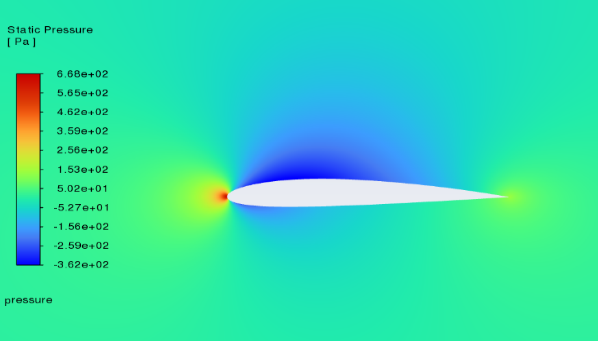
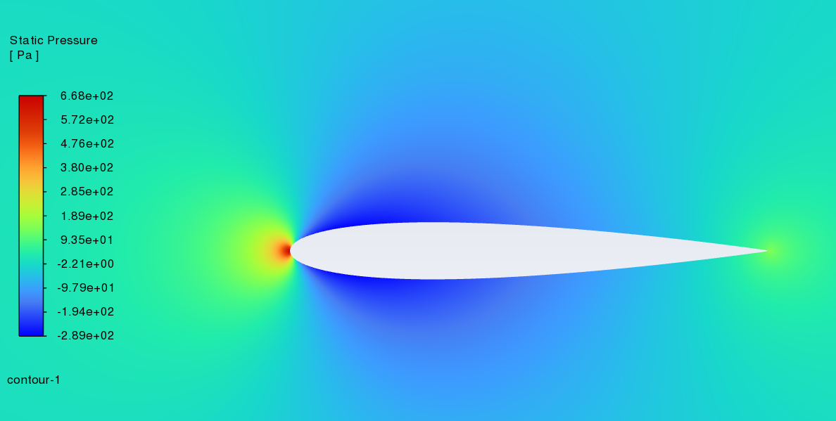
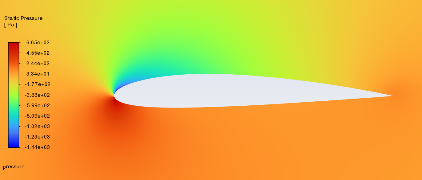
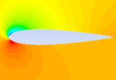
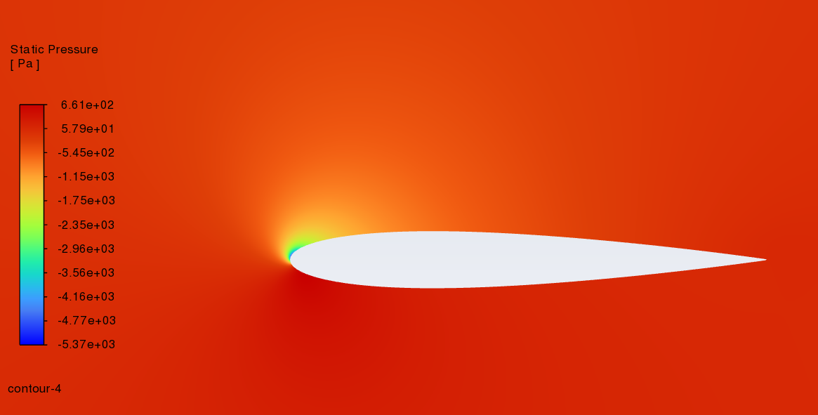
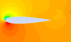
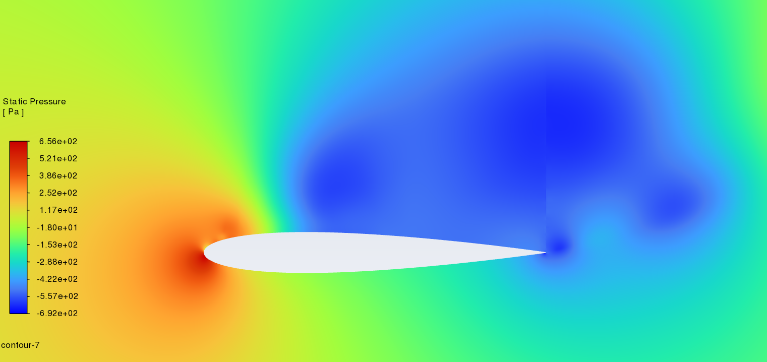
3.1. Pressure distribution cloud image
Figure 6 shows static pressure cloud images of NACA2412 and NACA0012 between 0-18° angles of attack. (left----NACA2412 right----NACA0012) With the increase of the angle of attack, the pressure centre of the low-pressure area on the upper surface gradually moves to the leading edge. The above phenomenon is reflected in NACA2412 and NACA0012. It is worth noting that the stagnation point is located at the leading edge, where the static pressure is highest. According to the lift theory, when there is a certain pressure difference between the upper surface and the lower surface of the aerofoil, the airflow can effectively push the wing upward and generate lift. For NACA2412, as the angle of attack increases, there is a more pronounced effect between the lower pressure region and higher-pressure region that creates more lift force until the angle reaches a certain point. After the angle reaches that point, there will be no more lift force created. For NACA0012, as it is a symmetrical aerofoil when the angle of attack is 0, it creates very little lift force because there is no pressure difference between its upper and lower surfaces. When the angle of attack increases, it creates lift force just like other types of aerofoils, and with the increase of the angle of attack, the lift-drag ratio also increases gradually. As the angle reaches a certain point, the lift-drag ratio will meet its max value and then fall, eventually it becomes very unstable.
0°angle of attack
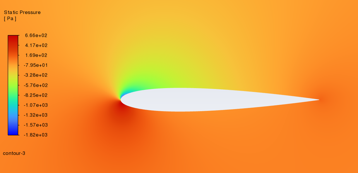
6°angle of attack
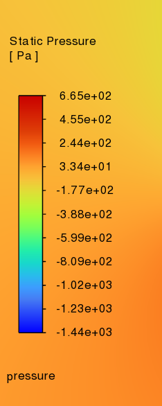
12°angle of attack

18°angle of attack
Figure 6: Pressure distribution cloud image at different angles of attack
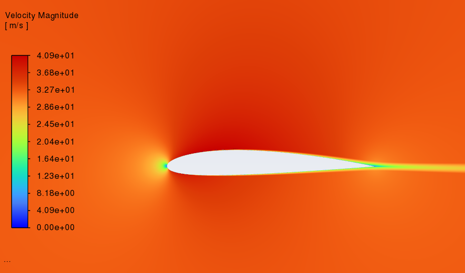
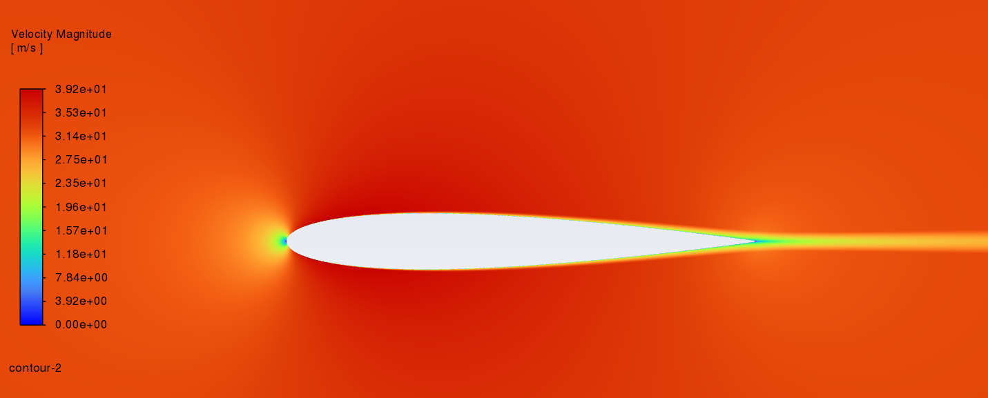
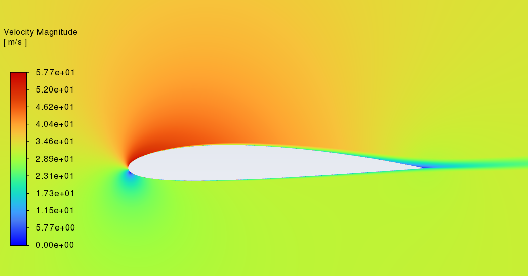
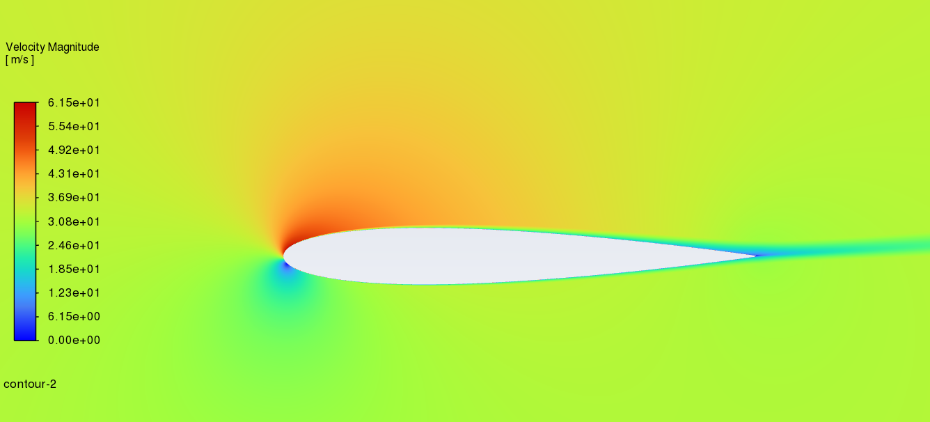
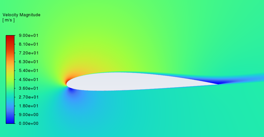
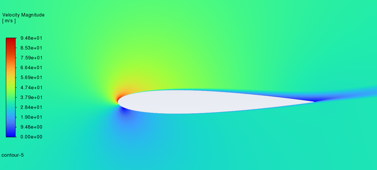
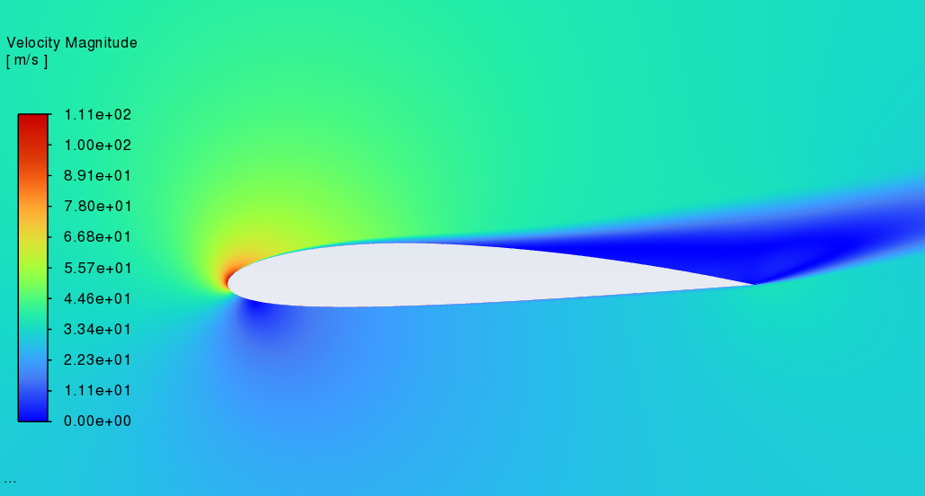
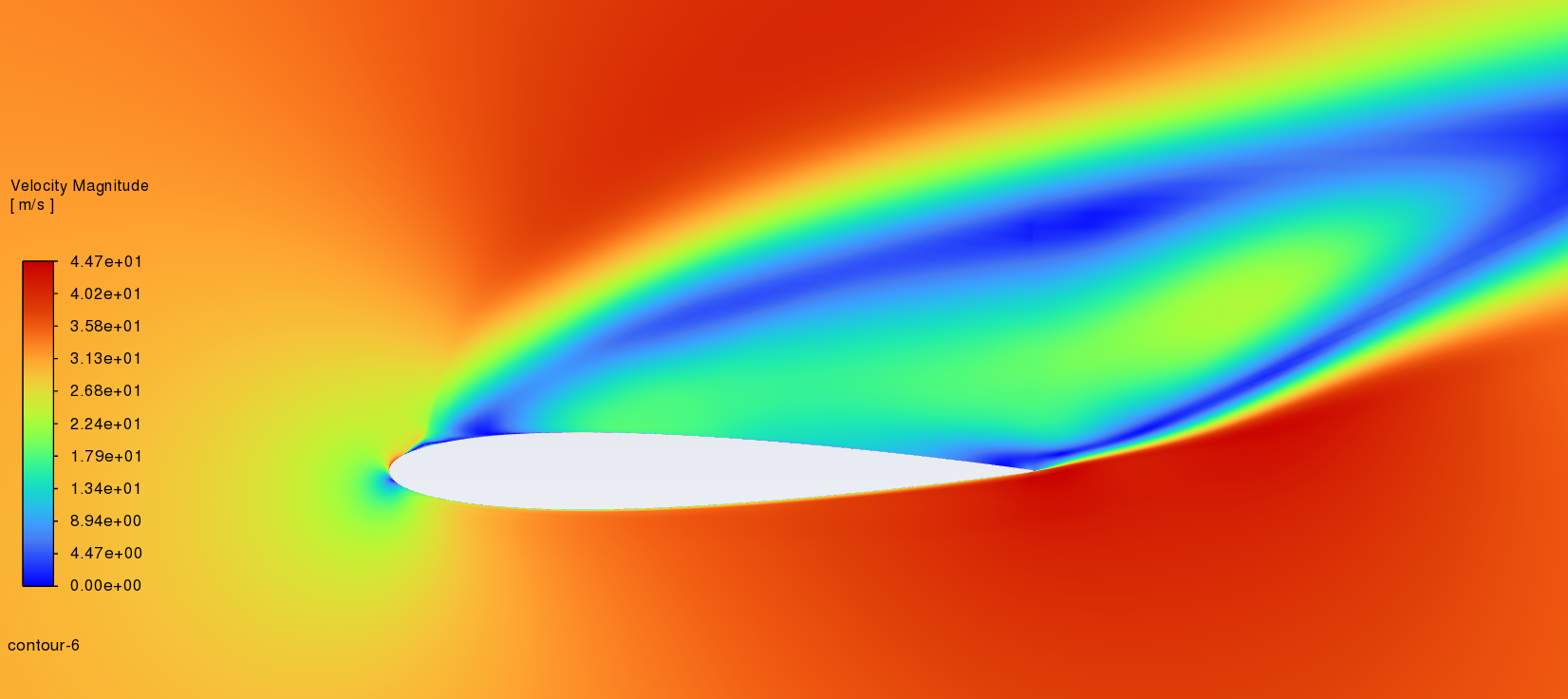
3.2. Velocity distribution cloud image
Figure 7 shows the velocity distribution of NACA2412 and NACA0012 between 0°to 18° Angle of attack. (left----NACA2412 right----NACA0012) At the first three angles, these two aerofoils are similar in velocity distribution cloud image. According to the Bernoulli principle, if the velocity of a fluid rises, its static pressure must correspondingly decrease to maintain equilibrium. [8]. So, before the angle of attack increases, the speed of air on the upper and lower surfaces is close so there is no obvious difference in pressure. With the increment of the angle of attack, the area of higher speed becomes smaller while the low-speed zone is the opposite.
0°angle of attack
6°angle of attack
12°angle of attack
18°angle of attack
Figure 7: Distribution velocity cloud map at different angles of attack
3.3. Aerodynamic characteristics at different angles of attack
From Figure 8 and Table 3, we can see NACA2412 has better performance between 0-18 angle of attack which provides more lift force at low speed. However, NACA0012 has a lower drag coefficient which can fly smoother compared with NACA2412. (blue----NACA2412 orange----NACA0012)
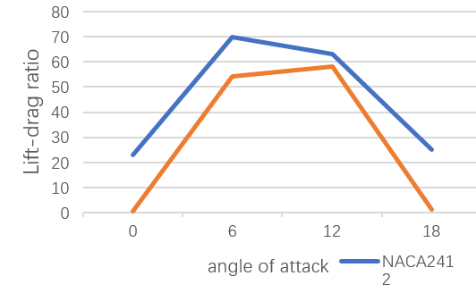
Figure 8: The lift-drag ratio for NACA2412 and NCAA0012 at different angles of attack
Table 3: Lift and drag coefficient for NACA2412 and NCAA0012 at different angles of attack
Angle of attack | Lift coefficient | Drag coefficient | ||
0 | 0.21 | 0.005 | 0.009 | 0.009 |
6 | 0.84 | 0.64 | 0.012 | 0.011 |
12 | 1.39 | 1.21 | 0.022 | 0.020 |
18 | 1.55 | 0.28 | 0.061 | 0.22 |
4. Conclusion
For this paper, the aerodynamic properties of the NACA2412 and NACA0012 airfoils are studied comprehensively based on ANSYS Fluent. The SA turbulence model and finite volume method are applied to simulate the two-dimensional flow characteristics, and the pressure distribution, velocity distribution, and aerodynamic properties of the aerofoil at various angles of attack are analysed. The research conclusions of this paper are as follows:
(1)NACA2412 has a higher lift-drag ratio, which provides more lift force for aircraft.
(2)NACA0012 has a lower drag coefficient while flying thus it has a positive effect on the manoeuvring of the aircraft
(3) At a low Reynolds number (2.2×10*6), the drag coefficient increases with the angle of attack for both.
(4) At a low Reynolds number (2.2×10*6), the lift coefficient increases with the angle of attack for both until a certain angle, then tapers off.
(5) Neither of these aerofoils should be used at high angles of attack.
To sum up, in the selection of an aerofoil, the designer should choose the appropriate aerofoil according to the specific requirements of the aircraft. If the aircraft needs to fly smoothly between 6°-12°, the NACA 0012 is a better choice. If you need to generate higher lift at low speeds, the NACA 2412 May be more suitable. In addition, the performance of both aerofoils gradually declines beyond a certain angle so users should avoid using these two aerofoils at high angles of attack.
At the beginning of the process of building mesh, poor mesh quality affects the quality of the result seriously. The is a huge deviation from the NACA result between my result until I improve my mesh. After that, the gap between the new result and the NACA result is within acceptable limits.
Hope in the future to analyse with the more professional the methods and equipment and explore different parameters that influence the characteristics and performance of the aerofoil.
References
[1]. Sayel M. Fayyad, Aiman AL Alawin, Suleiman Abu-ein et al. (2024) Aerodynamics Analysis Comparison between NACA 4412 and NREL S823 Airfoils[J] E-ISSN: 2224-347X
[2]. Mangano M, Martins J R R A. (2021) Multipoint aerodynamic shape optimization for subsonic and supersonic regimes[J]. Journal of Aircraft, 58(3): 650-662.
[3]. Conlan-Smith C, Ramos-García N, Sigmund O, et al.(2020) Aerodynamic shape optimization of aircraft wings using panel methods[J]. AIAA Journal, 58(9): 3765-3776.
[4]. Karim Oukassoua, 0F, Sanaa El Mouhsineb, Abdellah El Hajjajia, Bousselham Kharbouch.(2019) Comparison of the power, lift and drag coefficients of wind turbine blades from aerodynamics characteristics of Naca0012 and Naca2412[J]. Procedia Manufacturing 32 983–990
[5]. Christian Busse, Andrew Kach, Stephan M.(2015) Wagner Boundary Conditions: What They Are, How to Explore Them, Why We Need Them, and When to Consider Them SSRN Electronic Journal DOI:10.2139/ssrn.2713980
[6]. P. R. Spalart, S. R. Allmaras. (1992), A One-Equation Turbulence Model for Aerodynamic Flows, AIAA-92-0439.
[7]. F. R. Menter, Zonal.(1993) Two Equation k-ω Turbulence Models for Aerodynamic Flows, AIAA Paper DOI:10.1063/1.4934721.
[8]. Lee Johnson (2022) Bernoulli's ---Principle: Definition, Equation, Examples[online]. https://sciencing.com/bernoullis-principle-definition-equation-examples-13723388.html
Cite this article
Gong,Z. (2025). CFD Analysis of NACA2412 and NACA0012 at Low Reynolds (2.2×10*6) Numbers Based on ANSYS Fluent. Applied and Computational Engineering,127,59-67.
Data availability
The datasets used and/or analyzed during the current study will be available from the authors upon reasonable request.
Disclaimer/Publisher's Note
The statements, opinions and data contained in all publications are solely those of the individual author(s) and contributor(s) and not of EWA Publishing and/or the editor(s). EWA Publishing and/or the editor(s) disclaim responsibility for any injury to people or property resulting from any ideas, methods, instructions or products referred to in the content.
About volume
Volume title: Proceedings of the 5th International Conference on Materials Chemistry and Environmental Engineering
© 2024 by the author(s). Licensee EWA Publishing, Oxford, UK. This article is an open access article distributed under the terms and
conditions of the Creative Commons Attribution (CC BY) license. Authors who
publish this series agree to the following terms:
1. Authors retain copyright and grant the series right of first publication with the work simultaneously licensed under a Creative Commons
Attribution License that allows others to share the work with an acknowledgment of the work's authorship and initial publication in this
series.
2. Authors are able to enter into separate, additional contractual arrangements for the non-exclusive distribution of the series's published
version of the work (e.g., post it to an institutional repository or publish it in a book), with an acknowledgment of its initial
publication in this series.
3. Authors are permitted and encouraged to post their work online (e.g., in institutional repositories or on their website) prior to and
during the submission process, as it can lead to productive exchanges, as well as earlier and greater citation of published work (See
Open access policy for details).
References
[1]. Sayel M. Fayyad, Aiman AL Alawin, Suleiman Abu-ein et al. (2024) Aerodynamics Analysis Comparison between NACA 4412 and NREL S823 Airfoils[J] E-ISSN: 2224-347X
[2]. Mangano M, Martins J R R A. (2021) Multipoint aerodynamic shape optimization for subsonic and supersonic regimes[J]. Journal of Aircraft, 58(3): 650-662.
[3]. Conlan-Smith C, Ramos-García N, Sigmund O, et al.(2020) Aerodynamic shape optimization of aircraft wings using panel methods[J]. AIAA Journal, 58(9): 3765-3776.
[4]. Karim Oukassoua, 0F, Sanaa El Mouhsineb, Abdellah El Hajjajia, Bousselham Kharbouch.(2019) Comparison of the power, lift and drag coefficients of wind turbine blades from aerodynamics characteristics of Naca0012 and Naca2412[J]. Procedia Manufacturing 32 983–990
[5]. Christian Busse, Andrew Kach, Stephan M.(2015) Wagner Boundary Conditions: What They Are, How to Explore Them, Why We Need Them, and When to Consider Them SSRN Electronic Journal DOI:10.2139/ssrn.2713980
[6]. P. R. Spalart, S. R. Allmaras. (1992), A One-Equation Turbulence Model for Aerodynamic Flows, AIAA-92-0439.
[7]. F. R. Menter, Zonal.(1993) Two Equation k-ω Turbulence Models for Aerodynamic Flows, AIAA Paper DOI:10.1063/1.4934721.
[8]. Lee Johnson (2022) Bernoulli's ---Principle: Definition, Equation, Examples[online]. https://sciencing.com/bernoullis-principle-definition-equation-examples-13723388.html