


1. Introduction
The research history of oximeters can be traced back to the 1930s and 1940s, initially designed to monitor the blood oxygen saturation of fighter pilots flying at high altitudes. Over time, these devices evolved into detecting the blood oxygen content of patients in hospitals. Nowadays, people generally use oximeters to provide auxiliary detection for their own physical health. The earliest oximeters were mostly implemented using ear probe sensors, which were not conducive to daily use. Zhangyuan Luo and others [1] designed an ear hanging oximeter, but this type of sensor faced challenges in terms of stability and convenience for regular use. Min Liu and others [2] designed a finger clip oximeter, which has made new progress in stable measurement and portability compared to previous research designs, but has limitations in portability and universality. This type of oximeter has some limitations on the thickness of the fingers, for example, it cannot be stably clamped on a baby's fingers for stable detection. Pang, G. and others [3] designed a portable oximeter that can stably measure blood oxygen data at the wrist. Shakhreet, B. Z. and others [4] designed a pulse oximeter that can detect real-time blood oxygen data. However, due to hardware limitations and environmental noise, the design did not achieve the expected measurement accuracy. With the development of sensors, some fully functional sensors can solve the above problems, such as MAX30102. Pengfei Bai [5] and others designed a blood oxygen meter based on nRF52832 on the basis of MAX30102, but it can only measure blood oxygen.
Based on these advancements, this article designs a blood oxygen meter based on STM32 using MAX30102, which combines multiple sensors to measure temperature and step count on the basis of measuring blood oxygen, further improving the existing functions of the blood oxygen meter.
2. Design Overview
Designing a portable, multi-sensor, and adaptive oximeter is an important project that can significantly improve personal health monitoring capabilities. The primary goal of this oximeter is not only to meet basic blood oxygen monitoring needs but also to integrate advanced sensor technology to achieve comprehensive health monitoring for users. Additionally, the system aims to offer a user-friendly interface and timely health alerts.
Referring to the design of Zhihui He and others [6], the system designed in this article mainly includes the following parts:
1. MAX30102 Sensor Module:
The MAX30102 sensor module, a highly integrated optical heart rate and blood oxygen monitoring sensor, is one of the core components of the system, used for non-invasive measurement of blood oxygen saturation and heart rate. It can provide accurate detection results in low-power mode, and it emits red and infrared light, calculating blood oxygen saturation based on the difference in absorption of these two types of light by oxygenated hemoglobin and reduced hemoglobin in the blood.
2. DS18B20 Temperature Sensor Module:
The DS18B20 temperature sensor module is mainly used to measure the user’s body temperature and can provide high-precision temperature data. It also plays an important role in detecting fever and understanding the impact of environmental temperature changes on health.
3. ADXL345 Three-Axis Sensor Module:
The ADXL345 three-axis sensor module is responsible for capturing the user's activity status, obtaining step information, and providing operational data. This sensor helps monitor daily movements and contributes to the overall health tracking process.
4.Data Processing and Control Module:
Data processing and control module: this module is built based on the microcontroller STM32F103c8t6, which is responsible for receiving data from various sensors, processing, analyzing, and sending the results to the display module and alarm module. In addition, the main control can also drive the alarm module based on the self set health data threshold.
5. Display Module:
The OLED screen is used as the display unit due to its advantages, including bright colors, high contrast, and low energy consumption. OLED screens are very suitable for portable devices due to their bright colors, high contrast, and low energy consumption.
6.Alarm Module:
When the user's health indicators exceed the safe range, the alarm module will sound an alarm through a buzzer. This feature is crucial for alerting users or nearby emergency personnel in case of an emergency.
3. Hardware Design
Figure 1 shows the overall circuit diagram of the oximeter. To ensure aesthetics and safety in circuit design, a 5V power supply is designed below the system, and all module power supply terminals are connected to the 5V power line. The grounding wire is designed at the top of the system to facilitate the connection of all module grounding wires.
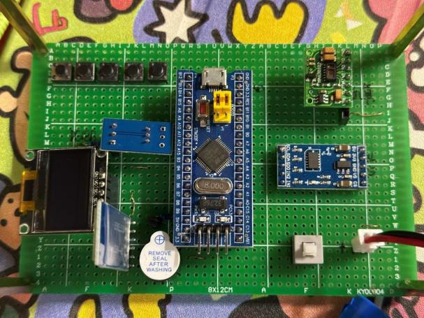
Figure 1: General Circuit Diagram
3.1. Selection of main control chip
This design selects the STM32F103c8t6 chip with the smallest system board as the main control part. The STM32F103C8T6 minimum system board is a basic development platform that integrates the STM32F103C8T6 chip microcontroller, widely used in embedded systems, IoT devices, and various small and medium-sized projects.
Compared to using the STM32F103C8T6 chip, this minimal system board not only has a high-performance STM32F103C8T6 microcontroller built-in but also provides the following circuits:
(1) Necessary power supply circuit: The onboard power conversion circuit converts the external 5V or 3.3V input voltage into the 3.3V voltage required by the microcontroller, simplifying power supply design.
(2) Crystal oscillator circuit: Onboard 8MHz or 72MHz crystal oscillator ensures stable and reliable clock signal of the microcontroller.
(3) Reset circuit: Integrated reset button and reset circuit, convenient for system reset and debugging operations.
Compared to using other microcontrollers, this minimal system version has simple and rich peripheral interfaces:
(1) I2C interface: This device is equipped with multiple I2C interfaces, which makes it convenient and efficient to connect sensors that rely on the I2C communication protocol, such as MAX30102 heart rate and blood oxygen sensors, ADXL345 three-axis accelerometers, etc.
(2) UART interface: It integrates one or more UART interfaces, supports serial communication, and facilitates data exchange with devices such as HC-05 Bluetooth modules.
(3) SPI interface: onboard SPI interface, capable of interacting with devices such as OLED displays that require high-speed communication.
USB interface: Integrated USB interface, supports programming and debugging through USB cable, simplifies the development process.
(4) Expansion pins: Provides a large number of GPIO pins and expansion interfaces, which can flexibly connect various peripherals and sensors.
3.2MAX30102 Sensor Module Circuit Design
3.1.1. MAX30102 Sensor Module Introduction
The MAX30102 module integrates optical sensors and signal processors, widely used in medical fields such as heart rate monitoring, pulse oxygen saturation monitoring, and other biological parameter detection. It has the characteristics of high integration, low power consumption, and high precision, and can detect heart rate and blood oxygen saturation in real time, making it an ideal choice for this design.
The MAX30102 module integrates infrared LED, red light LED, and photodetector internally. The skin is illuminated by the infrared LED and red light LED, and the photodetector collects the reflected light signal to calculate blood oxygen saturation and heart rate. Moreover, the module also has functions such as automatic gain control, ambient light suppression, and motion suppression, which can effectively remove interference signals and improve monitoring accuracy, greatly simplifying the software design of the system.
3.1.2. MAX30102 Sensor Module Wiring
The working voltage of the MAX3010 module is between 1.8V-5V. The VIN pin of the MAX30102 sensor can be connected to a 5V power supply, and the GND pin can be grounded. To ensure that the MAX30102 chip and STM32 chip can communicate correctly through I2C, SDA pin is connected to the PB11 pin while the STM32 chip and the SCL pinned to the PB10 pin.
3.2. DS18B20 Temperature Sensor Module Circuit Design
3.2.1. Introduction to DS18B20 Temperature Sensor Module
This design uses DS18B20 module as the temperature sensor module. This module is a highly integrated, low-power, high-precision digital temperature sensor widely used in fields such as healthcare, environmental monitoring, and smart homes. This module is capable of real-time monitoring of temperature and providing accurate temperature data through a digital interface, thus meeting the portable requirements of this design.
The DS18B20 module integrates temperature sensors, signal processors, and digital interfaces internally. During operation, the temperature sensor senses temperature changes in the surrounding environment and converts the temperature signal into a digital signal. The signal processor further processes these digital signals and transmits the temperature data to the main control chip through a 1-Wire digital interface.
3.2.2. DS18B20 sensor module wiring
Connect the VCC pin of DS18B20 to a 5V power supply, ground the GND pin, and connect the DQ pin to the PA11 pin of STM32 chip to transmit data to the main control chip.
3.3. ADXL345 three-axis sensor module circuit design
3.3.1. Introduction to ADXL345 three-axis sensor module
The ADXL345 three-axis acceleration sensor module is a highly integrated, low-power, high-precision digital acceleration sensor widely used in fields such as motion monitoring, health equipment, and the Internet of Things. This module can monitor the user's acceleration data in real-time in three-dimensional space and provide accurate motion information through a digital interface, which can provide precise step data for this design.
The ADXL345 module integrates three-axis acceleration sensors, signal processors, and digital interfaces internally. During operation, the acceleration sensor senses the user's acceleration changes in the X, Y, and Z directions and converts the acceleration signal into an electrical signal. The signal processor further processes these electrical signals and transmits acceleration data to the main control chip through I2C or SPI digital interfaces. The ADXL345 also features low noise, built-in motion detection, and a configurable sampling rate, making it perform well in various application scenarios.
3.4. Display Module Design
3.4.1. Introduction to OLED module
The OLED display module is a highly integrated, low-power, high contrast micro display screen widely used in portable devices such as smart watches, environmental monitoring devices, medical equipment and other fields. This module can display text, graphics, and image information in real time, and communicate with the main control chip through a digital interface, which is highly compatible with the visibility requirements of this design. Due to the size limitation of the circuit board, this design uses an OLED screen with a size of 0.96 memory.
The OLED display module integrates organic light-emitting diodes (OLEDs) and display driver chips internally. When working, the main control chip sends display data through the I ² C or SPI digital interface, and the driver chip converts these data into corresponding electrical signals to control the OLED pixels to emit light, thereby displaying content on the display screen. OLED technology has self luminous characteristics and does not require a backlight source, thus achieving a perfect black display on a black background, improving contrast and display effect.
3.4.2. OLED module wiring
Connect the VCC pin of the OLED to a 5V power supply and ground the GND pin. In order to ensure that the main control chip can control the OLED display normally, it is necessary to connect the SCL pin of the OLED to the PB6 pin of the STM32 chip and the SDA pin to the PB7 pin of the STM32 chip.
3.5. Hardware Expansion Module Design
In order to further enhance the practicality of the multifunctional health monitor, this design integrates an HC-05 Bluetooth module on the hardware circuit. The HC-05 Bluetooth module is a commonly used serial Bluetooth module that supports the Bluetooth 2.0 standard and has advantages such as low power consumption, long transmission distance, and stable communication. By integrating the HC-05 Bluetooth module, users can connect their health monitor with smart devices such as smartphones in wireless conditions, making it more convenient to obtain and detect data. Due to the complexity and time constraints, only the Bluetooth module was designed in the hardware circuit part of this design, and no corresponding startup program was designed in the software, so Bluetooth communication cannot be carried out.
In terms of hardware connection, the VCC pin of the HC-05 module needs to be connected to a 5V power supply, and the GND pin needs to be grounded. To achieve communication with the STM32 microcontroller, connect the TX pin of HC-05 to the RX pin of STM32 (e.g. PA10), and connect the RX pin of HC-05 to the TX pin of STM32 (e.g. PA9).
Through the above hardware circuit design, the normal power supply and use of each functional module can be ensured, and all functional modules can be connected to STM32 so that STM32 can receive data from each module normally and also ensure STM32's control over each module.
4. Software Design
Software design includes the main program, interrupt handling program, OLED display driver program, delay function program, key processing program, real-time clock program, temperature sensor program, algorithm program for calculating heart rate and blood oxygen saturation (SpO2), I2C communication program, accelerometer program, USART communication program, blood oxygen sensor program, and timer program. This section introduce the program implementation for calculating heart rate and blood oxygen saturation (SpO2), as well as reading heart rate and blood oxygen saturation using the MAX30102 sensor.
4.1. Calculate heart rate
(1) Remove DC component
Calculate the average value of the IR (Infrared Signal) signal, which represents the DC component of the signal. The formula is as follows:
\( un\_ir\_mean=\frac{\sum _{k=0}^{n\_ir\_buffer\_length-1}pun\_ir\_buffer[k]}{n\_ir\_buffer\_length} \) (1)
Subtract the average value from the original IR signal to remove the DC component, and invert the signal to convert the position of the detection valley value into the detection peak value. The formula is as follows:
\( an\_x[k]=-1×(pun\_ir\_buffer[k]-un\_ir\_mean) \) (2)
(2) Smooth IR signal
Use a 4-point moving average filter to smooth the signal and reduce the impact of noise. The formula is as follows:
\( an\_x[k]=\frac{\sum _{j=0}^{3}an\_x[k+j]}{4} \) (3)
(3) Set threshold
Calculate the average value of the inverted signal and set a suitable threshold (usually between 30 and 60) for detecting peak values. The formula is as follows:
\( n\_th1=\frac{\sum _{k=0}^{BUFFER\_SIZE-1}an\_x[k]}{BUFFER\_SIZE} \) (4)
(4) Peak detection
Detect the peak position in the inverted signal using the maxim_ffind_peaks function. Due to the signal and inversion, these peak positions are actually valley positions in the original IR signal.
(5) Calculate heart rate
Calculate the average interval time between adjacent valley positions, and use this average interval time to calculate heart rate. The formula is as follows:
\( heart\_rate=\frac{40×60}{n\_peak\_interval\_sum} \) (5)
Among them, 40 represents sampling 40 times per second, and 60 represents the number of seconds in one minute.
4.2. Calculation of Blood Oxygen Saturation
(1) Calculate AC and DC components
Find the maximum AC and DC components of the IR and Red signals between the valley positions of each cardiac cycle. AC represents the alternating current variation of the optical signal, and DC component represents the direct current component of the optical signal.
(2) Calculate ratio
Calculate the AC/DC ratio of IR and Red signals, and based on these ratios, determine the relative concentrations of hemoglobin and oxygenated hemoglobin using the following formula:
\( a{n_{ratio[k]}}=(\frac{n\_y\_ac×n\_x\_dc\_max}{n\_x\_ac×n\_y\_dc\_max})×100 \) (6)
(3) Search for SpO2 value
Use the already defined uch_stpo_2 table to find the SpO2 value closest to the ratio.
The defined uch_stpo_2 table is shown in Figure 2:
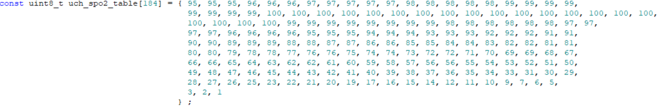
Figure 2: Definition of uch_stpo_2 table
4.3. Reading and calculating heart rate and blood oxygen saturation
This section of code is divided into the following parts:
(1) Initialize the I2C interface, configure clock frequency and other parameters to enable the system to communicate normally.
(2) Reset the MAX30102 sensor to its initial state.
(3) Read the value of the interrupt status register and store it in uch_rummy for subsequent interrupt processing.
(4) Initialize the MAX30102 sensor and configure parameters such as sampling frequency and mode.
(5) Read the sensor data of the first 150 infrared and red LEDs and store it in the aun_ir_buffer and aun_ded_buffer; Determine the minimum value un_min and maximum value un_max of the signal for subsequent signal processing and LED brightness calculation.
(6) The maxim-hert_rate_ond_oxygen_staturation function calculates the heart rate and blood oxygen saturation corresponding to these signal data.
(7) Update signal range: Move the data in the buffer areas aun_ded_buffer and aun_ir_buffer by 50 positions, and discard the first 50 old data. Calculate the latest signal range un_in and un_max:
un_min=min(un_min,aun_red_buffer[i-50])
un_max=max(un_max,aun_red_buffer[i-50])
(8) Read 50 new samples from MAX30102FFO and update them to aun_ded_buffer and aun_ir_buffer. Real time calculation of LED brightness un_rightness based on changes in red LED data.
If the current sample value is greater than the previous sample value, then:
\( Δ=aun\_red\_buffer[i]-un\_prev\_data \) (7)
Otherwise:
\( Δ=un\_prev\_data-aun\_red\_buffer[i] \) (8)
Calculate the percentage change and convert it to brightness:
\( f\_temp=|\frac{Δ}{un\_max-un\_min}|×MAX\_BRIGHTNESS \) (9)
Update brightness:
\( un\_brightness+=sign(Δ)×(-f\_temp) \) (10)
(9) Calculate heart rate and blood oxygen saturation every 8 calls to the ReadHeartRateSpO2 function.
5. Experimental comparison
At the same time period and under the same circumstances, the blood oxygen levels of the same person were measured, and the results are shown in Figure 3:
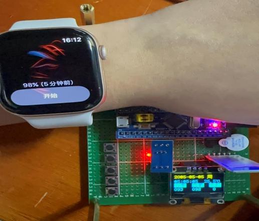
Figure 3: Comparison of Results
(Due to the circuit board being placed horizontally on the desktop, the measured step count was 0; the initial time was set as shown in the above figure and was not changed to the experimental date during the experiment.)
Based on the above results, it can be concluded that the accuracy of the blood oxygen data measured by the system is not significantly different from that measured by the Apple Watch.
6. Conclusion
This article designs and implements a multi-sensor integrated oximeter based on STM32 microcontroller. This device not only measures blood oxygen saturation but also integrates multiple functions such as heart rate monitoring, temperature detection, and step counting. A high-precision and feature rich health monitoring system was constructed using the STM32F103C8T6 as the core control unit, combined with MAX30102 heart rate and blood oxygen sensor, DS18B20 temperature sensor, and ADXL345 three-axis acceleration sensor. Experimental data shows that the blood oxygen saturation data measured by this device is similar to that of the Apple Watch, meeting the expected accuracy requirements of the design. In addition, the system is equipped with OLED display screens and buzzer alarm functions, further enhancing the user experience and system security. This design provides a comprehensive and portable solution for personal health management.
However, due to time and other constraints, the Bluetooth communication module has not yet been fully developed. Future work can enhance the system by adding Bluetooth communication functionality, enabling the transmission of collected data to designated applications on smartphones or tablets, thereby facilitating more convenient data acquisition and monitoring.
References
[1]. Luo, Z., Guo, Q., Zheng, M., Yu, H., Zhu, C., Zhang, L., & Zhang, W. (2019). Design and implementation of an ear-mounted pulse oximeter. China Medical Device Information, 25(03), 15-18+41. https://doi.org/10.15971/j.cnki.cmdi.2019.03.005 (in Chinese)
[2]. Liu, M., & Li, X. (2021). Design of a clip-on pulse oximeter based on a photodiode sensor. Electronic Testing, 47(15), 21-22+50. https://doi.org/10.16520/j.cnki.1000-8519.2021.15.006 (in Chinese
[3]. Pang, G., & Ma, C. (2014). A neo-reflective wrist pulse oximeter. IEEE access, 2, 1562-1567.
[4]. Shakhreet, B. Z., & Shakhreet, M. Z. (2018). Design of pulse oximetry system. J. Basic Appl. Res. Int, 18, 3457.
[5]. Bai, P., Liu, Q., Duan, F., An, Q., de Rooij, N. F., Li, N., & Zhou, G. (2017). Design of a wearable pulse oximetry system based on MAX30102. Laser & Infrared, 47(10), 1276-1280.
[6]. He, Z., Wang, J., Liu, Y., Ren, X., & Cui, W. (2021). Design and implementation of a portable, low-power pulse oximeter based on STM32. Journal of Yan’an University (Natural Science Edition), 40(03), 79-82. https://doi.org/10.13876/J.cnki.ydnse.2021.03.079
Cite this article
Wang,Z. (2025). Design of Multi Sensor Integrated Oximeter Based on STM32. Applied and Computational Engineering,133,96-104.
Data availability
The datasets used and/or analyzed during the current study will be available from the authors upon reasonable request.
Disclaimer/Publisher's Note
The statements, opinions and data contained in all publications are solely those of the individual author(s) and contributor(s) and not of EWA Publishing and/or the editor(s). EWA Publishing and/or the editor(s) disclaim responsibility for any injury to people or property resulting from any ideas, methods, instructions or products referred to in the content.
About volume
Volume title: Proceedings of the 5th International Conference on Signal Processing and Machine Learning
© 2024 by the author(s). Licensee EWA Publishing, Oxford, UK. This article is an open access article distributed under the terms and
conditions of the Creative Commons Attribution (CC BY) license. Authors who
publish this series agree to the following terms:
1. Authors retain copyright and grant the series right of first publication with the work simultaneously licensed under a Creative Commons
Attribution License that allows others to share the work with an acknowledgment of the work's authorship and initial publication in this
series.
2. Authors are able to enter into separate, additional contractual arrangements for the non-exclusive distribution of the series's published
version of the work (e.g., post it to an institutional repository or publish it in a book), with an acknowledgment of its initial
publication in this series.
3. Authors are permitted and encouraged to post their work online (e.g., in institutional repositories or on their website) prior to and
during the submission process, as it can lead to productive exchanges, as well as earlier and greater citation of published work (See
Open access policy for details).
References
[1]. Luo, Z., Guo, Q., Zheng, M., Yu, H., Zhu, C., Zhang, L., & Zhang, W. (2019). Design and implementation of an ear-mounted pulse oximeter. China Medical Device Information, 25(03), 15-18+41. https://doi.org/10.15971/j.cnki.cmdi.2019.03.005 (in Chinese)
[2]. Liu, M., & Li, X. (2021). Design of a clip-on pulse oximeter based on a photodiode sensor. Electronic Testing, 47(15), 21-22+50. https://doi.org/10.16520/j.cnki.1000-8519.2021.15.006 (in Chinese
[3]. Pang, G., & Ma, C. (2014). A neo-reflective wrist pulse oximeter. IEEE access, 2, 1562-1567.
[4]. Shakhreet, B. Z., & Shakhreet, M. Z. (2018). Design of pulse oximetry system. J. Basic Appl. Res. Int, 18, 3457.
[5]. Bai, P., Liu, Q., Duan, F., An, Q., de Rooij, N. F., Li, N., & Zhou, G. (2017). Design of a wearable pulse oximetry system based on MAX30102. Laser & Infrared, 47(10), 1276-1280.
[6]. He, Z., Wang, J., Liu, Y., Ren, X., & Cui, W. (2021). Design and implementation of a portable, low-power pulse oximeter based on STM32. Journal of Yan’an University (Natural Science Edition), 40(03), 79-82. https://doi.org/10.13876/J.cnki.ydnse.2021.03.079