


1. Introduction
Estimating the camera pose is a fundamental challenge in various applications that require precise environmental localization, such as in robotics [1–2]. Achieving accurate camera pose estimation from images involves identifying correspondences between known reference points in the environment and their projections in the camera’s view. Some methods rely on natural features, like key points or textures, to establish these correspondences [3-4]. However, fiducial markers remain a popular choice due to their ease of detection and the ability to deliver high-speed, accurate results [5]. Among the different types of fiducial markers explored in the literature, square markers have become particularly favored for their simplicity and effectiveness [5-6]. Pose estimation using square markers is typically based solely on RGB images, where the camera pose is derived from the four corners of the marker, assuming the camera is properly calibrated. However, integrating these markers with depth-sensing cameras opens up new possibilities for more robust and accurate pose estimation, leveraging the additional depth information to enhance precision and reliability in various environments.
This paper compares the precision of translation vector (tvec) estimation using two different methods: traditional RGB images and the enhanced approach that incorporates depth sensing. By evaluating the performance of both methods, this study aims to highlight the advantages and potential limitations of integrating depth data in camera pose estimation.
2. Pose Estimation and Depth sensing
Pose estimation is a critical task in many computer vision applications, such as robot navigation, augmented reality, and autonomous systems. It involves determining correspondences between 3D points in the physical environment and their 2D projections in an image. This task is often challenging due to noise, distortion, and environmental complexities. To overcome these issues, synthetic or fiducial markers are frequently used to simplify the process of point detection and matching.
Fiducial markers are specially designed patterns that provide a reliable reference for detecting poses in real-world environments. A fiducial marker system typically consists of a predefined set of valid markers and an algorithm that detects these markers in images and corrects for potential errors (e.g., noise or distortion). Among the most popular fiducial markers are binary square markers, which are notable for their simplicity and robustness. The structure of these markers, typically composed of a black square border with a unique internal binary code, enables error detection and correction techniques, enhancing their reliability even in challenging conditions.
One widely used fiducial marker library is the ArUco library, developed by Rafael Muñoz and Sergio Garrido [6]. Integrated into OpenCV as the aruco module, this library specializes in detecting square fiducial markers, such as those shown in Fig. 1, and estimating camera pose from the four corners of a single marker. The binary nature of these markers allows the system to provide enough correspondences to compute the camera pose effectively, which is crucial in applications where real-time performance and robustness are required.
This paper leverages the ArUco marker system, using OpenCV for marker detection and pose estimation, to implement a reliable integration with depth sensing.
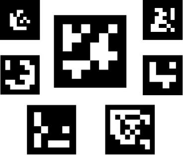
Figure 1: Example of ArUco markers images.
Depth sensing is a key technology in computer vision, enabling systems to perceive and interpret the 3D structure of a scene by capturing depth information alongside standard RGB images [7]. This capability is crucial in applications such as object recognition, scene understanding, human-computer interaction, and autonomous navigation. One of the most widely adopted depth sensing solutions for consumer and research applications is Intel RealSense.
Intel RealSense offers portable, consumer-grade Red, Green, Blue, and Depth (RGBD) sensors that provide real-time depth computation through hardware acceleration over a USB connection. These sensors are particularly popular in fields like computer vision, human-computer interaction, and robotics.
This paper uses the Intel RealSense D435i, a robust and versatile depth sensor. It features high-precision depth sensing capabilities and provides real-time 3D perception, making it an ideal choice for detecting the depth of markers. More detailed information about the hardware is provided in the subsequent section.
3. Hardware specifications and software tools
Table 1: Hardware Specifications of Intel RealSense D435i [8]
Features | Use environment: Indoor/Outdoor | Ideal range: .3 m to 3 m |
Image sensor technology: Global Shutter | ||
Depth | Depth technology: Stereoscopic | Depth Field of View (FOV): 87 × 58 |
Minimum depth distance (Min‑Z) at max resolution: ~28 cm | Depth output resolution:Up to 1280 × 720 | |
Depth Accuracy: <2% at 2 m1 | Depth frame rate: Up to 90 fps | |
RGB | RGB frame resolution: 1920 × 1080 | RGB sensor FOV (H × V): 69 × 42 |
RGB frame rate: 30 fps | RGB sensor resolution: 2 MP | |
RGB sensor technology: Rolling Shutter | ||
Major Components | Camera module:Intel RealSense Module D430 + RGB Camera | Vision processor board:Intel RealSense Vision Processor D4 |
Physical | Form factor: Camera Peripheral | Connectors: USB‑C 3.1 Gen 1 |
Length × Depth × Height:90 mm × 25 mm × 25 mm | Mounting mechanism:– One 1/4‑20 UNC thread mounting point.– Two M3 thread mounting points. |
The following data, specific to the Intel RealSense D435i camera this paper uses, were obtained using the Intel librealsense SDK.
Principal Point:
\( p[\begin{matrix}644.885 & 383.783 \\ \end{matrix}] \)
Focal Length:
\( f[\begin{matrix}909.568 & 908.917 \\ \end{matrix}] \)
Intrinsic Matrix Values:
\( [\begin{matrix}909.56781006 & 0. & 644.88494873 \\ 0. & 908.91687012 & 383.78311157 \\ 0. & 0. & 1. \\ \end{matrix}] \)
Inverse Brown Conrady:
\( [\begin{matrix}0. & 0. & \begin{matrix}0. & 0. & 0. \\ \end{matrix} \\ \end{matrix}] \)
In this paper, two primary software tools were used for depth sensing and marker detection. The aruco module from the Python OpenCV library was employed for detecting and interpreting ArUco markers, enabling reliable pose estimation. Additionally, pyrealsense2, a Python wrapper for the Intel librealsense SDK, was utilized to interface with the RealSense D435i camera. This library provides device control and facilitates the retrieval of depth and RGB data, as well as device-specific calibration parameters essential for accurate depth mapping and spatial analysis.
4. Methodology
This section outlines the step-by-step procedure employed for depth estimation and pose calculation using an ArUco marker detected through an Intel RealSensThis section outlines the step-by-step procedure employed for depth estimation and pose calculation using an ArUco marker detected through an Intel RealSense D435i camera, leveraging OpenCV’s aruco module and Intel’s pyrealsense2 library in Python. The workflow consists of capturing RGB and depth images, detecting the ArUco marker, aligning depth and RGB frames, calculating 3D pose vectors, and performing calibration with depth-based and 2D-only techniques.e D435i camera, leveraging OpenCV’s aruco module and Intel’s pyrealsense2 library in Python.
The first step is capturing RGB frames, as shown in Fig. 2, and depth frames, as shown in Fig. 3. The RealSense D435i camera captures both RGB and depth frames. Using the pyrealsense2 library, frames are streamed synchronously, laying the foundation for accurate marker-based depth analysis.
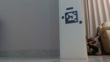
Figure 2: RGB frame retrieved from the camera.
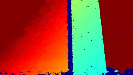
Figure 3: Depth frame retrieved from the camera.
The second step is detecting and preprocessing ArUco markers. The RGB frame is processed to detect the ArUco marker. OpenCV’s aruco module identifies the marker ID, corners, and center of the marker, which are essential for pose estimation.
ArUco marker detection is a process that identifies specific, square-shaped fiducial markers in an image, each containing a unique binary code within a black border. Detection starts with converting the RGB image into a thresholded (binary) image, highlighting high-contrast areas where the ArUco markers are likely located. The thresholded image emphasizes black and white regions, allowing the algorithm to quickly identify quadrilateral shapes. Once potential markers are located, the algorithm analyzes the inner binary pattern within each detected square to verify it as an ArUco marker and decode its ID. This pattern is unique for each marker, enabling reliable detection even in noisy or complex environments. The algorithm then extracts the four corners and center of each detected marker, which are used for pose estimation and depth mapping. With the thresholded RGB image as shown in Fig. 4, the detection process can be visually illustrated, showing how the high-contrast image assists in isolating and identifying the ArUco marker accurately. After the detection, the center point of the marker is calculated by averaging the detected corner coordinates.
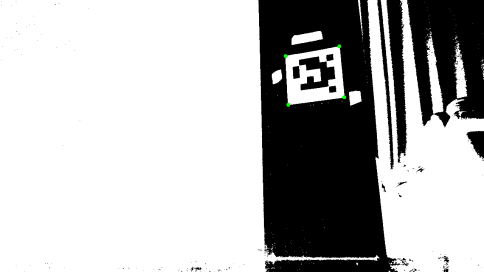
Figure 4: Thresholded image, showing the highlighted corners of the ArUco marker.
The third step is depth frame alignment. To obtain an accurate depth value for the marker, depth frames are aligned with RGB frames using pyrealsense2’s alignment functions. This process is crucial for accurate depth mapping, as it ensures that the depth and RGB coordinates correspond spatially.
The fourth step is determining marker depth. The aligned depth frame provides a depth value at each pixel location. By querying the pixel coordinates of the ArUco marker’s center in the depth frame, the exact depth distance of the marker from the camera can be retrieved.
The fifth step is retreiving camera intrinsics. Accurate pose estimation and depth mapping require knowledge of the camera’s intrinsic parameters, which include the focal lengths, principal point, and distortion coefficients. These intrinsic parameters define how the camera projects 3D points onto the 2D image plane and are essential for aligning depth and RGB data precisely.
Using pyrealsense2, the intrinsic parameters of the Intel RealSense D435i are retrieved directly from the camera’s onboard calibration data. These parameters include the focal lengths (fx, fy), which define the scaling from real-world distances to pixel distances along the x and y axes, and the principal point (cx, cy), representing the coordinates of the image center while accounting for any offset in the camera’s sensor alignment. Additionally, the distortion coefficients are obtained to correct lens distortion, ensuring accurate alignment of depth and RGB points, even at the edges of the image. These parameters are critical components of the hardware specifications described earlier, underscoring their role in ensuring precise pose estimation.
The sixth step is determing tvec and rvec. Using OpenCV’s built-in function, rotation and translation vectors (rvec and tvec) are calculated for the ArUco marker. With pyrealsense2, translation vectors can be calculated using the depth obtained from the fourth step instead. The camera matrix and distortion coefficients obtained from the RealSense device-specific calibration data are used as inputs for accurate rvec and tvec calculation. These vectors represent the marker’s orientation and position relative to the camera. Calibration data from the Intel RealSense D435i is incorporated here to refine the pose estimation.
5. Data collection and analysis
To evaluate the precision of depth-based and RGB-only pose estimation methods, testing was conducted at four camera positions relative to the marker. At each position, the marker’s tvec and rvec values were recorded 50 times. Following data collection, outliers were removed, particularly frames where the depth data was erroneous (e.g., instances of zero depth due to sensor limitations). After error removal, the remaining values at each position were averaged to provide a representative tvec and rvec value for each method.
The averaged data (Avg) from each position along with their coefficient of variation (Cv) to reveal the consistency of each method’s pose estimation are presented in Table 2.
Table 2: Rvec and tvec estimation using both methods.
Avg rvec (ArUco) | Cv rvec (ArUco) | Avg tvec (ArUco) | Cv tvec (ArUco) | Avg tvec (Depth) | Cv tvec (Depth) | |
Position a | 2.604 0.196 1.319 | 0.16 2.06 0.45 | -59.8 -120.6 674.5 | 0.34 0.24 0.23 | -58.9 -114.8 639.7 | 0.44 0.35 0.31 |
Position b | 2.875 -0.026 0.046 | 0.42 13.14 27.93 | 18.3 -71.0 830.9 | 1.22 0.30 0.34 | 17.1 -66.8 788.4 | 2.55 0.61 0.23 |
Position c | 2.595 -0.190 -1.283 | 0.15 1.93 0.42 | 163.2 -97.9 736.0 | 0.26 0.33 0.27 | 158.3 -94.1 705.8 | 0.20 0.45 0.18 |
Position d | 2.722 -0.143 -1.016 | 0.30 3.32 1.24 | -1.9 131.9 1615.8 | 3.57 0.88 0.73 | -1.5 126.1 1545.5 | 0.14 0.28 0.14 |
The comparison of precision between the two methods of calculating tvec — using RGB data via ArUco markers and using depth data—revealed noteworthy trends based on the marker's distance from the camera. At close ranges (600 mm to 800 mm), both methods exhibited similar precision, indicating that ArUco-based calculations are effective within this range. However, at greater distances (e.g., 1500 mm), the depth-based method demonstrated significantly higher consistency. This discrepancy can likely be attributed to the reliance of the ArUco method on 2D RGB data. As markers move farther from the camera, their projections on the image plane shrink, and the geometric distortions or pixelation in the image introduce inaccuracies in corner detection and shape reconstruction. Depth data, in contrast, directly provides spatial information, maintaining precision even at larger distances.
The implementation of the proposed method demonstrated sufficient computational efficiency to operate in real-time. The camera captured frames at 30 frames per second (fps), and the processing pipeline, including ArUco marker detection, depth alignment, and pose estimation, did not introduce significant delays or bottlenecks. This suggests that the method is suitable for applications requiring real-time performance, such as robotics or augmented reality, where maintaining frame rate is critical.
While the results provide valuable insights into the performance of pose estimation using ArUco markers and depth data, several limitations in the experimental setup must be acknowledged. Firstly, the experimental setup was relatively basic, which may impact the overall credibility of the findings. Additionally, the scenarios tested were constrained to a limited range of camera angles and distances, reducing the generalizability of the results to more diverse real-world conditions. Furthermore, the absence of a reliable ground truth or reference system prevented the measurement of accuracy, restricting the analysis to relative precision between methods. This experiment also did not evaluate the performance of rvec estimation using depth data. According to the results, the precision of ArUco-based rvec estimation is noticeably poor when the camera is oriented directly toward the marker, likely due to limitations in 2D marker detection under such conditions. Future work could explore the feasibility of using depth data for rvec estimation, which may offer improved precision in such scenarios.
6. Conclusion
This study explores the use of ArUco markers and depth data for pose estimation, highlighting that depth integration offers significant advantages in improving the precision of translation vector calculations, particularly at longer ranges. The findings suggest that depth-based methods could address the limitations of traditional RGB-based marker systems, especially in challenging scenarios such as direct camera-marker alignment. This integration may pave the way for more accurate and robust marker systems, with potential applications in robotics, augmented reality, and beyond. Future experiments should focus on evaluating rotation vector estimation using depth, expanding test scenarios, and employing controlled environments to further validate and refine these methods.
References
[1]. R. T. Azuma. (1997). A survey of augmented reality. Presence, 6, 355–385.
[2]. B. Williams, M. Cummins, J. Neira, P. Newman, I. Reid, J. Tardós. (2009). A comparison of loop closing techniques in monocular SLAM. Robotics and Autonomous Systems, 57(11), 1188–1197.
[3]. W. Daniel, R. Gerhard, M. Alessandro, T. Drummond, S. Dieter. (2010) Real-time detection and tracking for augmented reality on mobile phones. IEEE Trans. Vis. Comput. Graph, 16 (3) 355–368.
[4]. G. Klein, D. Murray. (2007). Parallel tracking and mapping for small AR workspaces. In Proceedings of the 2007 6th IEEE and ACM International Symposium on Mixed and Augmented Reality, ISMAR 007, IEEE Computer Society, Washington, DC, USA, 1–10.
[5]. K. Mikolajczyk, C. Schmid. (2001). Indexing based on scale invariant interest points. In ICCV, 525–531.
[6]. OpenCV Documentation. (2024). Detection of ArUco Markers. https://docs.opencv.org/5.x/d5/dae/tutorial_aruco_detection.html.
[7]. Leonid Keselman, John Iselin Woodfill, Anders Grunnet-Jepsen, Achintya Bhowmik. (2017). Intel RealSense Stereoscopic Depth Cameras. In Proceedings of the IEEE Conference on Computer Vision and Pattern Recognition (CVPR) Workshops, 1-10.
[8]. Intel RealSense. (2024). Tech Specs of Intel RealSense Depth Camera D435i. https://www.intelrealsense.com/depth-camera-d435i/#.
Cite this article
Song,Y. (2025). Enhancing Pose Estimation with Depth Integration: A Comparative Study of ArUco Markers and Depth Data. Applied and Computational Engineering,133,183-189.
Data availability
The datasets used and/or analyzed during the current study will be available from the authors upon reasonable request.
Disclaimer/Publisher's Note
The statements, opinions and data contained in all publications are solely those of the individual author(s) and contributor(s) and not of EWA Publishing and/or the editor(s). EWA Publishing and/or the editor(s) disclaim responsibility for any injury to people or property resulting from any ideas, methods, instructions or products referred to in the content.
About volume
Volume title: Proceedings of the 5th International Conference on Signal Processing and Machine Learning
© 2024 by the author(s). Licensee EWA Publishing, Oxford, UK. This article is an open access article distributed under the terms and
conditions of the Creative Commons Attribution (CC BY) license. Authors who
publish this series agree to the following terms:
1. Authors retain copyright and grant the series right of first publication with the work simultaneously licensed under a Creative Commons
Attribution License that allows others to share the work with an acknowledgment of the work's authorship and initial publication in this
series.
2. Authors are able to enter into separate, additional contractual arrangements for the non-exclusive distribution of the series's published
version of the work (e.g., post it to an institutional repository or publish it in a book), with an acknowledgment of its initial
publication in this series.
3. Authors are permitted and encouraged to post their work online (e.g., in institutional repositories or on their website) prior to and
during the submission process, as it can lead to productive exchanges, as well as earlier and greater citation of published work (See
Open access policy for details).
References
[1]. R. T. Azuma. (1997). A survey of augmented reality. Presence, 6, 355–385.
[2]. B. Williams, M. Cummins, J. Neira, P. Newman, I. Reid, J. Tardós. (2009). A comparison of loop closing techniques in monocular SLAM. Robotics and Autonomous Systems, 57(11), 1188–1197.
[3]. W. Daniel, R. Gerhard, M. Alessandro, T. Drummond, S. Dieter. (2010) Real-time detection and tracking for augmented reality on mobile phones. IEEE Trans. Vis. Comput. Graph, 16 (3) 355–368.
[4]. G. Klein, D. Murray. (2007). Parallel tracking and mapping for small AR workspaces. In Proceedings of the 2007 6th IEEE and ACM International Symposium on Mixed and Augmented Reality, ISMAR 007, IEEE Computer Society, Washington, DC, USA, 1–10.
[5]. K. Mikolajczyk, C. Schmid. (2001). Indexing based on scale invariant interest points. In ICCV, 525–531.
[6]. OpenCV Documentation. (2024). Detection of ArUco Markers. https://docs.opencv.org/5.x/d5/dae/tutorial_aruco_detection.html.
[7]. Leonid Keselman, John Iselin Woodfill, Anders Grunnet-Jepsen, Achintya Bhowmik. (2017). Intel RealSense Stereoscopic Depth Cameras. In Proceedings of the IEEE Conference on Computer Vision and Pattern Recognition (CVPR) Workshops, 1-10.
[8]. Intel RealSense. (2024). Tech Specs of Intel RealSense Depth Camera D435i. https://www.intelrealsense.com/depth-camera-d435i/#.