


1. Introduction
In modern society, the rapid increase in vehicle numbers has made traffic congestion and long-distance driving major challenges for drivers. Traditional cruise control (CC) can maintain a constant vehicle speed on highways but still requires frequent driver intervention when encountering slowing or stopping vehicles, failing to fully relieve the driver's workload[1]. The emergence of Adaptive Cruise Control (ACC) has filled this gap[2].
ACC is an advanced driver assistance system (ADAS) designed to improve driving comfort and safety [3,4]. It automatically adjusts the vehicle's speed to maintain a safe distance from the preceding vehicle, thereby reducing driver fatigue during long-distance and congested traffic conditions [5]. With the development of autonomous driving technology, ACC has gradually become an essential feature in modern vehicles. By utilizing sensors such as radar and cameras, the ACC system continuously monitors the road conditions ahead and automatically adjusts the vehicle’s speed to maintain a safe distance[6]. This not only significantly reduces driver fatigue in long-distance and congested driving conditions but also effectively decreases the occurrence of traffic accidents. Studies have shown that vehicles equipped with ACC can significantly reduce the rate of rear-end collisions and enhance driving safety on highways [7].
During operation, ACC vehicles must handle complex traffic conditions. To ensure both safety and comfort, speed and distance control must be as smooth as possible. However, seamless switching in complex scenarios poses a significant challenge. To address this, researchers have conducted extensive studies. Pan et al. developed an adaptive cruise control system with a two-layer structure based on optimal control theory and hierarchical control [8]. In the system, the upper layer calculates the optimal desired following acceleration based on optimal control theory, while the lower layer uses this desired acceleration as an input to control vehicle acceleration and deceleration. Simulation experiments demonstrated that this system achieves effective adaptive cruise control while ensuring safety, tracking accuracy, and adaptability. Liu et al. proposed an adaptive sliding mode controller under a bidirectional guided-following communication topology, which improves the stability of vehicle platooning under communication interruptions[9]. Simulation experiments confirmed that this controller enhances platoon stability while reducing variations in inter-vehicle distance and improving road traffic efficiency. Guo et al. introduced an adaptive cruise control system based on fuzzy model predictive control and machine learning sensors[10]. Deep learning sensors were used to collect vehicle torque data, improving torque distribution efficiency. Additionally, a target function was established based on comfort and tracking performance indicators, with dynamically adjusted weighting factors based on vehicle safety strength. Constraints were set to adapt to different driving scenarios. Experimental results demonstrated that this method achieves better tracking accuracy and stability compared to traditional methods.
2. Background Knowledge
The control decision process of ACC is generally as follows: First, the ACC system utilizes LiDAR, cameras, wheel speed sensors, and other sensing devices to collect information about the vehicle’s own state and its surrounding environment. The data gathered by these sensors allow the system to accurately identify its position and status while tracking the precise location of the preceding vehicle, providing a data foundation for the subsequent decision-making phase. Next, based on driving requirements and the data collected by the sensors, the adaptive cruise controller is designed. The main function of this controller is to determine appropriate speed and following distance strategies by integrating the preceding vehicle's position and speed, system-set speed values, and the driver’s operational commands. Finally, the ACC system presents the current vehicle state and decision-making information in data form to the driver, while the system actuators execute the controller's commands to ensure that the vehicle follows the preceding car at the designated speed and following distance. The process is illustrated in Figure 1.
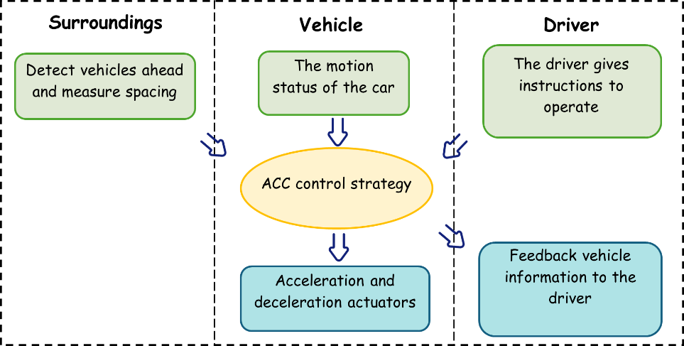
Figure 1: ACC Control Decision Flow Chart
The structure of the ACC system can be categorized into two main types: (1) End-to-End Direct Control Structure – The structure directly generates actuator commands based on sensor data. (2) Hierarchical Control Structure – This includes an upper-layer controller and a lower-layer controller. The upper-layer controller determines the vehicle’s desired speed or acceleration, while the lower-layer controller adjusts the throttle or braking to achieve these target values. This structure enables the ACC system to make intelligent control decisions based on different driving requirements and traffic conditions, enhancing driving comfort and safety.
The cruise speed control function is a critical sub-function of the ACC system. Its main objective is to detect static and dynamic objects directly ahead using sensor signals from cameras, radar, and other devices. It then regulates the vehicle’s speed to maintain a safe distance from the target vehicle. While driving, the driver can adjust the vehicle’s cruise speed using a cruise speed setting paddle or button. When no vehicle is ahead, the system accelerates or decelerates the vehicle to reach the preset speed and maintains that speed. When a preceding vehicle is detected, if the preset speed of the host vehicle exceeds the speed of the preceding vehicle, the system adjusts to follow the target vehicle's speed. If the preset speed is lower than that of the preceding vehicle, the vehicle continues at its preset speed.
The system operates as follows: a) No vehicle ahead – The vehicle cruises steadily at the driver-set speed. b) Vehicle detected ahead – The vehicle maintains the driver-defined safe following distance and follows the preceding vehicle's speed. c) Preceding vehicle stops – The vehicle automatically stops following the preceding vehicle. d) Preceding vehicle starts moving – The vehicle automatically resumes motion following the preceding vehicle or starts based on the driver’s command.
3. Methods Used in This Study
The speed control method used in the ACC system in this study is illustrated in Figure 2. The system first obtains environmental distance parameters through the Sensor program and passes them to the Target Selection program to determine the position and speed of the preceding vehicle. At the same time, the driver sets the target speed of the vehicle. These data are then integrated into the Cruise Control program, which takes the vehicle’s current state and the computed target state as input, processes them, and outputs the optimal acceleration to the Car program. The Car program implements this acceleration through throttle and braking, and all data are fed back to the Cruise Control program. Finally, the User Interface transmits the vehicle’s speed and acceleration data to the visualization program for output.
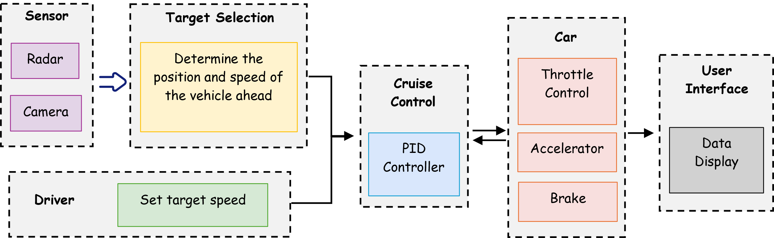
Figure 2: ACC System Control Speed Mode
The pseudo-code used in the paper is as follows:
Step1: Define the speed_object and distance_object in the class Sensor.
Step2: Define the set target speed from driver.
Step3: Define the formulary of the PID Controller and the numbers of kp, ki, kd.
Step4: Import Sensor and PID Controller to get the sensor data, a PID controller (P=0.8, I=0, D=0), and initial parameters for current speed, set speed, and a stored previous target speed for rate limiting. Define the compute_safe_distance as the sum of current_speed * reaction_time, (current_speed ** 2) / (2 * comfortable_deceleration) and 2m buffer distance. Set the Speed Update Logic. The system first computes the compute_safe_distance and compares it to distance_object to get distance_error. Target speed is determined based on three conditions:
if distance_error > 0.5 * safe_distance: target_speed = set_speed
elif distance_error < 0.5 * safe_distance: target_speed = sensor_data.lead_speed - 2
else: target_speed = min(set_speed, sensor_data.lead_speed)
Define a maximum acceleration/deceleration of 2 m/s²which is enforced. If the target speed change exceeds this limit, it is clamped to ±2 m/s from the previous target speed. The updated target is stored for future iterations. Update the car’s speed using the acceleration which computed based on the error between target and current speed.
Step5: Define the CruiseControlAPP to visualize the data.
PID stands for Proportional (P), Integral (I), and Derivative (D), and it is a widely used control algorithm [11]. Due to its simple structure and strong robustness, the PID algorithm has been widely applied in engineering control. In the early development of adaptive cruise control, the PID control algorithm was the primary method used to control ACC systems [12]. In ACC systems, extensive research has been conducted on PID-based following modes and control strategies. The core idea is feedback control based on error reduction, continuously minimizing the deviation between the desired and actual values to stabilize the control system near the target value [13].
In traditional two-vehicle following dynamic models, the PID control algorithm has been extensively validated and demonstrated high reliability. In the PID algorithm: P (Proportional gain) contributes to stability by amplifying the control effect. I (Integral gain) helps eliminate steady-state errors. D (Derivative gain) predicts errors and enables rapid response. The PID algorithm used in this study converts continuous time into discrete time with a step size of 0.1 seconds. In the discrete-time implementation: The integral term is replaced by accumulation. The derivative term is approximated using first-order differencing. The PID control equation used in this study is given by Equation (1):
\( u(t)={K_{p}}{e_{n}}+{K_{i}}Δt\sum _{k=0}^{n}{e_{k}}+{K_{d}}\frac{{e_{n}}-{e_{n-1}}}{Δt}\ \ \ (1) \)
where, u(t) is the control output. en is the error at the current time step. t is the time step size. Kp, Ki and Kd are the proportional, integral, and derivative gains, respectively.
In automotive systems, spacing strategy determines the safe following distance during driving and serves as the reference input for subsequent control algorithms. This is the first step in designing the control system [14]. If the following distance is too short, it may lead to traffic accidents. If the following distance is too long, it reduces road capacity and increases the likelihood of lane-changing interruptions by adjacent vehicles. Thus, the quality of the spacing strategy directly affects driving safety, following performance, and road efficiency [15]. In the study, a dynamic spacing strategy based on constant headway time is adopted, adjusting the safe distance according to the driving environment. The corresponding safe distance equation is given by Equation (2):
\( {d_{safe}}=v\cdot {t_{r}}+\frac{{v^{2}}}{2a}+{d_{buffer}}\ \ \ (2) \)
where, dsafe is the safe following distance. v is the vehicle speed. tr is the headway time. a is the vehicle acceleration. dbuffer is the minimum safety buffer distance.
4. Experimental Results and Analysis
The experimental environment in this study includes the following: Hardware Environment: Intel Core i7-12700H 2.70GHz CPU, NVIDIA GeForce RTX 3060 GPU, 16.0GB Memory. Software Environment: Windows 11 Home Chinese Version, Python Programming Language, Anaconda Prompt as the environment management tool.
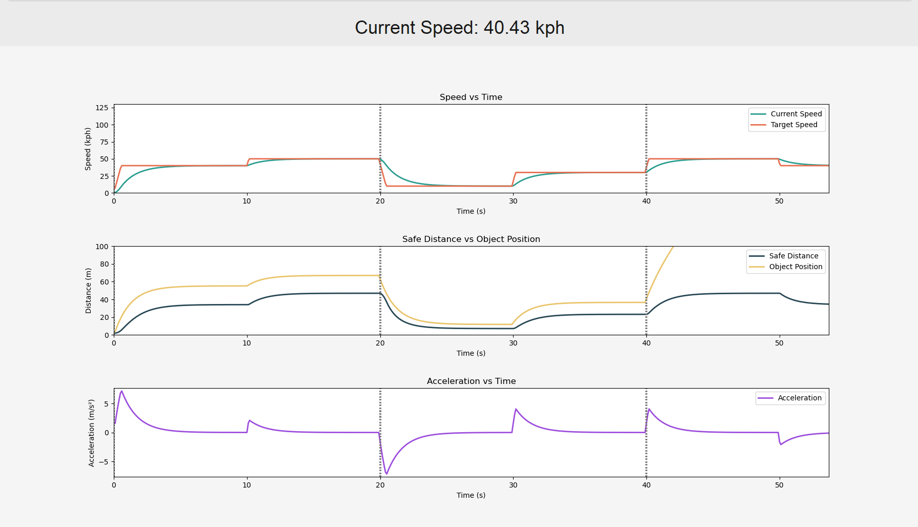
In the experiment, the preceding vehicle's speed changes every 10 seconds over a total duration of 50 seconds, following the sequence 40, 50, 10, 30, and 70 kph. The ego vehicle is set with a target speed of 50 kph, an initial speed of 0 kph, and an initial distance of 0 meters from the preceding vehicle. The simulated vehicle behavior within the 50-second duration is illustrated below.

(a) Variation Trend

(b) Optimized Code Version
Figure 3: Comparison of Current and Target Speed
Figure 3(a) presents the variation curve of the ego vehicle’s current speed and the model-fitted target speed. During the first 10 seconds, since the distance between the two vehicles is relatively short and the ego vehicle’s set speed exceeds the preceding vehicle’s speed, the ACC system restricts the target speed to 45 kph. Between 10-20 seconds, the preceding vehicle accelerates to 50 kph, and the ego vehicle also accelerates to 50 kph accordingly. Between 20-30 seconds, the preceding vehicle suddenly decelerates to 10 kph, and under the influence of the ACC system, the ego vehicle rapidly reduces its speed to 10 kph to maintain a safe distance. Between 30-40 seconds, the preceding vehicle accelerates to 30 kph, and the ego vehicle follows suit, accelerating to 30 kph. During 40-50 seconds, the preceding vehicle increases its speed to 70 kph, which exceeds the ego vehicle’s set speed. As a result, the ACC system removes the speed restriction, and the target speed returns to 50 kph. Figure 3(b) displays the updated visualization generated after optimizing the code.

(a) Variation Trend

(b) Optimized Code Version
Figure 4: Relation of Safe Distance and Object Position
Figure 4(a) illustrates the relationship between the safe following distance and the actual distance between the two vehicles. Under the ACC system's regulation, the actual distance consistently remains greater than the computed safe distance, ensuring safe driving between the two vehicles. Figure 4(b) presents the updated visualization after optimizing the code.
(a) Variation Trend
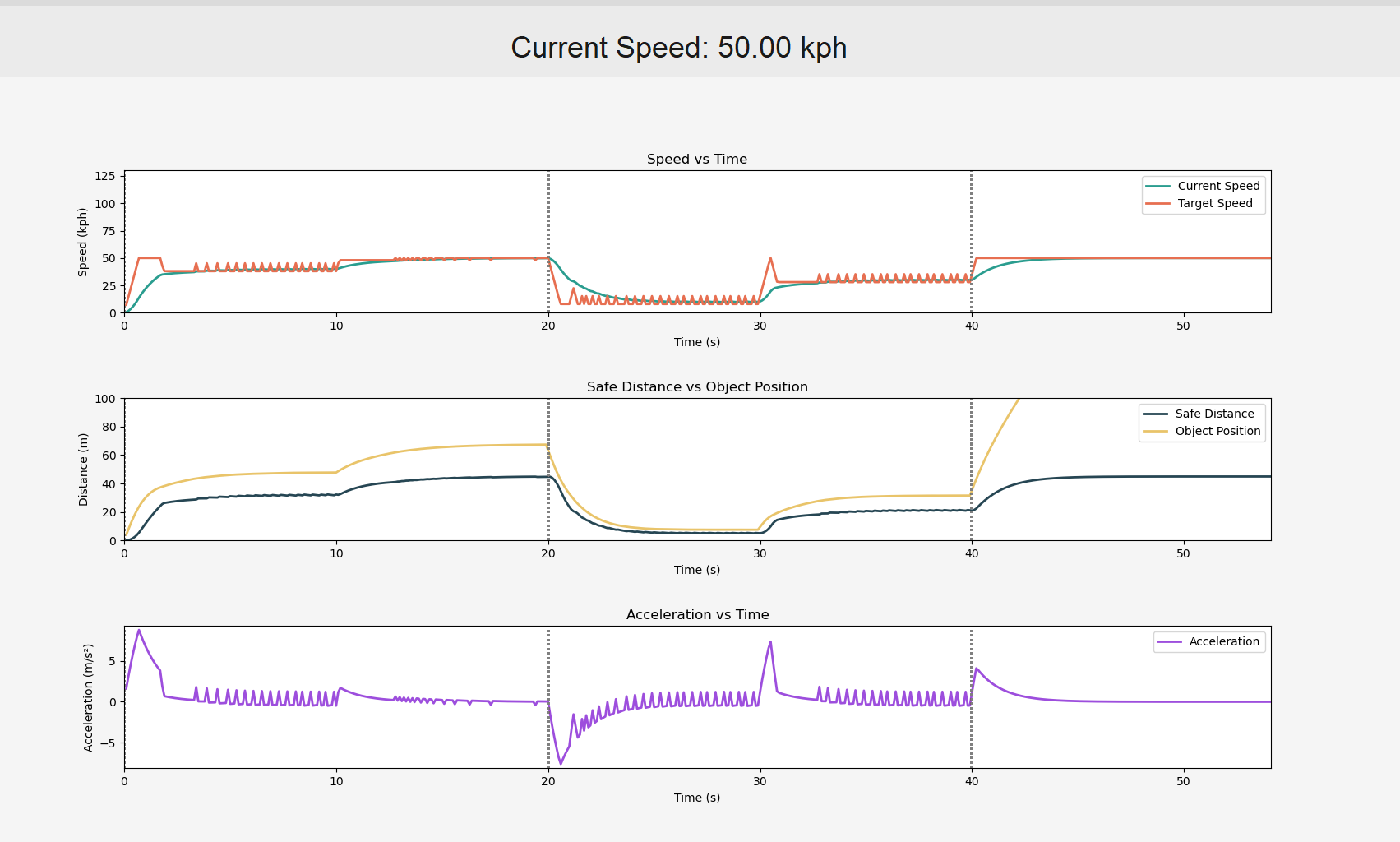
(b) Optimized Code Version
Figure 5: Acceleration of the Controlled Vehicle
Figure 5(a) displays the acceleration variation curve of the controlled vehicle. Under the influence of the PID control system, the ego vehicle continuously approaches the target speed. Consequently, the acceleration progressively decreases until it stabilizes at zero. Figure 5(b) shows the updated visualization after optimizing the code.
5. Conclusion
The paper presents an ACC method based on PID control and a dynamic safety distance strategy, effectively addressing the limitations of traditional cruise control in vehicle-following scenarios. By introducing a discrete PID algorithm and a dynamic headway adjustment mechanism, the proposed method significantly reduces speed fluctuations and driver fatigue during car-following operations. Experimental results demonstrate that this approach adjusts speed in real-time while maintaining a safe distance from the preceding vehicle, exhibiting excellent stability and responsiveness in acceleration, deceleration, and emergency braking scenarios. Furthermore, the method's robustness across different speed transition scenarios validates its practical application potential. Future work will focus on integrating LiDAR, V2X communication, and deep learning algorithms to enhance decision-making capabilities in complex traffic environments, advancing ACC systems toward higher levels of autonomous driving functionality. This study provides a theoretical foundation and engineering reference for optimizing intelligent driving assistance systems.
References
[1]. Izci D, Rizk-Allah R M, Ekinci S, et al. Enhancing time-domain performance of vehicle cruise control system by using a multi-strategy improved RUN optimizer[J]. Alexandria Engineering Journal, 2023, 80: 609-622.
[2]. Yu L, Wang R. Researches on Adaptive Cruise Control system: A state of the art review[J]. Proceedings of the Institution of Mechanical Engineers, Part D: Journal of Automobile Engineering, 2022, 236(2-3): 211-240.
[3]. Pan C, Huang A, Chen L, et al. A review of the development trend of adaptive cruise control for ecological driving[J]. Proceedings of the Institution of Mechanical Engineers, Part D: Journal of Automobile Engineering, 2022, 236(9): 1931-1948.
[4]. Li T, Chen D, Zhou H, et al. Car-following behavior characteristics of adaptive cruise control vehicles based on empirical experiments[J]. Transportation research part B: methodological, 2021, 147: 67-91.
[5]. Neumann T. Analysis of Advanced Driver-Assistance Systems for Safe and Comfortable Driving of Motor Vehicles[J]. Sensors, 2024, 24(19): 6223.
[6]. Log M M, Thoresen T, Eitrheim M H R, et al. Using Low-Cost Radar Sensors and Action Cameras to Measure Inter-Vehicle Distances in Real-World Truck Platooning[J]. Applied System Innovation, 2023, 6(3): 55.
[7]. Kamal M A S, Hashikura K, Hayakawa T, et al. Adaptive cruise control with look-ahead anticipation for driving on freeways[J]. Applied Sciences, 2022, 12(2): 929.
[8]. Jin J Y, Zhang J D, Zhang K P, et al. 3D multi-object tracking with boosting data association and improved trajectory management mechanism[J]. Signal Processing, 2024, 218 (2024) 109367.
[9]. Liu G, Zhao R, Su M. Cooperative adaptive sliding mode platoon control of intelligent connected vehicles under communication interruption[J]. International journal of automotive technology, 2023, 24(2): 513-525.
[10]. Guo J, Wang Y, Chu L, et al. Adaptive Cruise System Based on Fuzzy MPC and Machine Learning State Observer[J]. Sensors, 2023, 23(12): 5722.
[11]. Borase R P, Maghade D K, Sondkar S Y, et al. A review of PID control, tuning methods and applications[J]. International Journal of Dynamics and Control, 2021, 9: 818-827.
[12]. Joseph S B, Dada E G, Abidemi A, et al. Metaheuristic algorithms for PID controller parameters tuning: Review, approaches and open problems[J]. Heliyon, 2022, 8(5).
[13]. Somefun O A, Akingbade K, Dahunsi F. The dilemma of PID tuning[J]. Annual Reviews in Control, 2021, 52: 65-74.
[14]. Yimer T H, Wen C, Yu X, et al. A study of the minimum safe distance between human driven and driverless cars using safe distance model[J]. arXiv preprint arXiv:2006.07022, 2020.
[15]. Ro J W, Roop P S, Malik A. A new safety distance calculation for rear-end collision avoidance[J]. IEEE Transactions on Intelligent Transportation Systems, 2020, 22(3): 1742-1747.
Cite this article
Li,L. (2025). Adaptive Cruise Control Method for Automobiles Based on Dynamic Spacing Strategy & PID. Applied and Computational Engineering,141,106-112.
Data availability
The datasets used and/or analyzed during the current study will be available from the authors upon reasonable request.
Disclaimer/Publisher's Note
The statements, opinions and data contained in all publications are solely those of the individual author(s) and contributor(s) and not of EWA Publishing and/or the editor(s). EWA Publishing and/or the editor(s) disclaim responsibility for any injury to people or property resulting from any ideas, methods, instructions or products referred to in the content.
About volume
Volume title: Proceedings of the 3rd International Conference on Mechatronics and Smart Systems
© 2024 by the author(s). Licensee EWA Publishing, Oxford, UK. This article is an open access article distributed under the terms and
conditions of the Creative Commons Attribution (CC BY) license. Authors who
publish this series agree to the following terms:
1. Authors retain copyright and grant the series right of first publication with the work simultaneously licensed under a Creative Commons
Attribution License that allows others to share the work with an acknowledgment of the work's authorship and initial publication in this
series.
2. Authors are able to enter into separate, additional contractual arrangements for the non-exclusive distribution of the series's published
version of the work (e.g., post it to an institutional repository or publish it in a book), with an acknowledgment of its initial
publication in this series.
3. Authors are permitted and encouraged to post their work online (e.g., in institutional repositories or on their website) prior to and
during the submission process, as it can lead to productive exchanges, as well as earlier and greater citation of published work (See
Open access policy for details).
References
[1]. Izci D, Rizk-Allah R M, Ekinci S, et al. Enhancing time-domain performance of vehicle cruise control system by using a multi-strategy improved RUN optimizer[J]. Alexandria Engineering Journal, 2023, 80: 609-622.
[2]. Yu L, Wang R. Researches on Adaptive Cruise Control system: A state of the art review[J]. Proceedings of the Institution of Mechanical Engineers, Part D: Journal of Automobile Engineering, 2022, 236(2-3): 211-240.
[3]. Pan C, Huang A, Chen L, et al. A review of the development trend of adaptive cruise control for ecological driving[J]. Proceedings of the Institution of Mechanical Engineers, Part D: Journal of Automobile Engineering, 2022, 236(9): 1931-1948.
[4]. Li T, Chen D, Zhou H, et al. Car-following behavior characteristics of adaptive cruise control vehicles based on empirical experiments[J]. Transportation research part B: methodological, 2021, 147: 67-91.
[5]. Neumann T. Analysis of Advanced Driver-Assistance Systems for Safe and Comfortable Driving of Motor Vehicles[J]. Sensors, 2024, 24(19): 6223.
[6]. Log M M, Thoresen T, Eitrheim M H R, et al. Using Low-Cost Radar Sensors and Action Cameras to Measure Inter-Vehicle Distances in Real-World Truck Platooning[J]. Applied System Innovation, 2023, 6(3): 55.
[7]. Kamal M A S, Hashikura K, Hayakawa T, et al. Adaptive cruise control with look-ahead anticipation for driving on freeways[J]. Applied Sciences, 2022, 12(2): 929.
[8]. Jin J Y, Zhang J D, Zhang K P, et al. 3D multi-object tracking with boosting data association and improved trajectory management mechanism[J]. Signal Processing, 2024, 218 (2024) 109367.
[9]. Liu G, Zhao R, Su M. Cooperative adaptive sliding mode platoon control of intelligent connected vehicles under communication interruption[J]. International journal of automotive technology, 2023, 24(2): 513-525.
[10]. Guo J, Wang Y, Chu L, et al. Adaptive Cruise System Based on Fuzzy MPC and Machine Learning State Observer[J]. Sensors, 2023, 23(12): 5722.
[11]. Borase R P, Maghade D K, Sondkar S Y, et al. A review of PID control, tuning methods and applications[J]. International Journal of Dynamics and Control, 2021, 9: 818-827.
[12]. Joseph S B, Dada E G, Abidemi A, et al. Metaheuristic algorithms for PID controller parameters tuning: Review, approaches and open problems[J]. Heliyon, 2022, 8(5).
[13]. Somefun O A, Akingbade K, Dahunsi F. The dilemma of PID tuning[J]. Annual Reviews in Control, 2021, 52: 65-74.
[14]. Yimer T H, Wen C, Yu X, et al. A study of the minimum safe distance between human driven and driverless cars using safe distance model[J]. arXiv preprint arXiv:2006.07022, 2020.
[15]. Ro J W, Roop P S, Malik A. A new safety distance calculation for rear-end collision avoidance[J]. IEEE Transactions on Intelligent Transportation Systems, 2020, 22(3): 1742-1747.