


1. Introduction
Pulse-width modulation (PWM) rectifiers are classified into voltage source rectifiers (VSR) and current source rectifiers (CSR). Single-phase voltage source PWM rectifiers [1], characterized by reversible energy flow, adjustable output voltage, low grid-side current harmonic content, and stable unit power factor operation, have emerged as a research hotspot in the rectifier domain, widely applied in various industrial equipment such as UPS, communication power supplies, and electric vehicle charging systems. Research on single-phase VSR control strategies is critically important for effectively implementing power factor correction (PFC) and reducing total harmonic distortion (THD) of grid-side current.
At present, numerous studies on current control techniques for single-phase VSR have been conducted domestically and internationally, primarily encompassing hysteresis control [2], PR control [3], deadbeat control [4], and PI control. The hysteresis control structure is simple and robust, but the switching frequency varies with hysteresis width, causing high current harmonics and larger errors. PR control of the current inner loop effectively reduces grid-side current THD but exhibits limited stability margins sensitive to grid voltage frequency variations. The deadbeat control method provides rapid dynamic response and high tracking accuracy; however, it involves substantial computational complexity and poor robustness. PI control achieves rapid response and eliminates DC offset. Enhanced PI controllers further improve system stability and robustness, boasting simple structures and low implementation costs.
Currently, single-phase VSR extensively utilizes a dual-loop voltage-current control strategy, primarily regulating DC side voltage and grid-side current [5-6]. As an active front-end, single-phase VSR requires controlling DC-side output voltage. In the current loop, employing PI controllers necessitates obtaining sinusoidal AC voltage and current signals in the stationary αβ coordinate system through phase-locked techniques [7-8], then converting these signals into DC quantities via Park transformation in the synchronous rotating d-q coordinate system to execute feedforward decoupling control [9-11], thus achieving zero steady-state error tracking of AC current. However, the DQ current decoupling control involves multiple PI loops, impacting system dynamic response speed to some extent. It becomes challenging to attain high control performance and effectively suppress DC voltage fluctuations under strong disturbances or pronounced nonlinear characteristics of the controlled object [12-13]. Improved controllers, such as single-neuron PI controllers, calculate control law increments based on input weights, input magnitudes, and activation functions [14-15]. However, learning rates and transfer coefficients still significantly influence the dynamic response of the entire system. The control strategy proposed in reference [16] maintains converter stability under various disturbances but complicates the control structure and requires extensive computation.
Based on DQ current decoupling control of single-phase voltage source PWM rectifiers, this research first clarifies the circuit topology and constructs a mathematical model in the d-q rotating coordinate system. Subsequently, a single-neuron PI controller is designed for the voltage outer loop, and feedforward decoupling control is applied in the current inner loop. Lastly, reinforcement learning constitutes the upper layer, optimizing the initial parameters, the neuron's learning rate η, and the transfer coefficient K of the underlying single-neuron PI controller. Through comparative simulations involving sudden partial load removal and constant power load variations, the new reinforcement learning-based controller is evaluated against traditional PI and single-neuron PI controllers. Results validate the superior dynamic performance of the RL-integrated single-neuron PI controller in rapidly tracking DC bus voltage.
2. Working principle of single-phase VSR-PWM
2.1. PWM rectifier topology and mathematical model
Fig. 1 illustrates the primary circuit topology of a single-phase VSR. In this figure, \( {u_{s}} \) denotes the grid-side input voltage; \( {i_{s}} \) is the grid-side input current; L represents the AC-side filter inductance; Rs is the equivalent line impedance; \( {u_{ab}} \) indicates the AC-side input voltage of the full-bridge rectifier; C is the DC-side filter capacitor; RL stands for the load resistance; and S1~S4 represent the fully controlled switches MOSFETs of the rectifier.
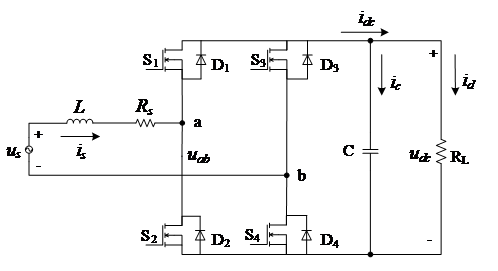
Figure 1: Topology of single-phase PWM rectifier
According to KVL, the single-phase VSR satisfies the following equation:
\( {u_{s}}=L\frac{d{i_{s}}}{dt}+{R_{s}}+{u_{ab}} \) (1)
To implement decoupled control for the current inner loop of the single-phase VSR, it is necessary to construct a virtual quantity lagging the grid voltage and current by 90°, subsequently employing Park transformation to derive the mathematical model in the d-q rotating coordinate system. This paper utilizes a second-order generalized integrator-based single-phase phase-locked loop (SOGI-PLL) to provide the angular frequency ω required by the Park transformation. Essentially, SOGI comprises a quadrature pair consisting of a second-order band-pass filter and a second-order low-pass filter, offering specific filtering effects. Its structural block diagram is shown in ref. [8]. Using SOGI-PLL, virtual orthogonal components \( {u_{sα}}、{u_{sβ}},{i_{sα}} 、{i_{sβ}} \) of the grid voltage \( {u_{s}} \) and grid current \( {i_{s}} \) in the stationary αβ and (3) from ref. [9] and equ. (7) and (8) from ref. [10], the mathematical model of the single-phase VSR in the d-q rotating coordinate system is acquired. Thus, voltage components \( {u_{sd}} \) , \( {u_{sq}} \) in the d-q rotating coordinate system are given as follows:
\( \begin{cases} \begin{array}{c} {u_{sd}}=L\frac{{di_{sd}}}{dt}+ωL{i_{sq}}+{u_{abd}} \\ {u_{sq}}=L\frac{{di_{sq}}}{dt}-ωL{i_{sd}}+{u_{abq}} \end{array} \end{cases} \) (2)
2.2. Voltage and current dual-loop control strategy
The control scheme of the single-phase VSR comprises two parts: the voltage outer-loop PI control and the current inner-loop DQ decoupling control. The overall control structure is illustrated in Fig. 2.
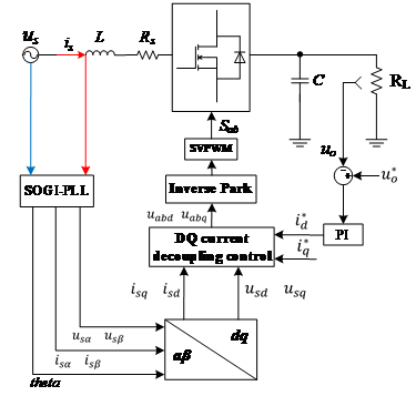
Figure 2: Block diagram of system control
When operating as an active front-end, the main objectives of the single-phase VSR control are maintaining constant DC-side voltage, achieving sinusoidal grid-side current, and ensuring operation at unity power factor. To maintain a stable DC-side voltage, the reference voltage \( u_{o}^{*} \) on the DC side is compared with the actual output voltage \( {u_{o}} \) . Their difference, after passing through a PI controller and limiter, serves as the reference current \( i_{d}^{*} \) for the grid-side current on the d-axis in the inner-loop current control. Thus:
\( i_{d}^{*}=({k_{p}}+\frac{{k_{i}}}{s})(u_{o}^{*}-{u_{o}}) \) (3)
From the Eq. (2) of the single-phase VSR in the d-q rotating coordinate system, the voltage components \( {u_{abd}} \) , \( {u_{abq}} \) of rectifier input voltage \( {u_{ab}} \) can be rearranged as follows:
\( \begin{cases} \begin{array}{c} {u_{abd}}={u_{sd}}-L\frac{{di_{sd}}}{dt}-ωL{i_{sq}} \\ {u_{abq}}={u_{sq}}-L\frac{{di_{sq}}}{dt}+ωL{i_{sd}} \end{array} \end{cases} \) (4)
Defining \( L\frac{{di_{s}}}{dt}=L\frac{i_{s}^{*}-{i_{s}}}{{T_{s}}}, where {T_{s}} is the switching period and i_{s}^{*} \) is the reference input current, the above equation simplifies to:
\( \begin{cases} \begin{array}{c} {u_{abd}}={u_{sd}}-L\frac{i_{sd}^{*}-{i_{sd}}}{{T_{s}}}-ωL{i_{sq}} \\ {u_{abq}}={u_{sq}}-L\frac{i_{sq}^{*}-{i_{sq}}}{{T_{s}}}+ωL{i_{sd}} \end{array} \end{cases} \) (5)
Based on Eq. (5), the control structure for DQ current decoupling is obtained, as illustrated in Fig. 3.
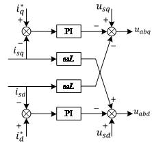
Figure 3: Diagram of DQ decoupling current control strategy
3. Design of single-neuron PI controller based on RL
3.1. Fundamental principles of RL
RL is a special class of algorithms in machine learning based on the Markov Decision Process (MDP). Its core idea involves an agent interacting with the environment to learn optimal strategies. The environment reinforces the agent's correct actions through rewards, prompting continuous improvement in behavior to maximize cumulative returns. The interaction workflow of reinforcement learning is depicted in Fig. 4, where the Agent represents the entity undergoing training, and the Environment is the entity with which the Agent interacts. The interaction occurs through actions, states, and rewards: at time step \( t \) , the Agent observes the current state ( \( {S_{t}} \) ), executes an action ( \( {A_{t}} \) ), subsequently observes the new state ( \( {S_{t+1}} \) ), and finally receives a reward ( \( {R_{t}} \) ). In brief, reinforcement learning aims to train the Agent to better interact with the Environment and thus achieve higher rewards.
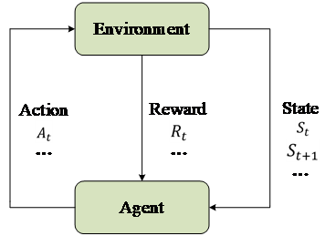
Figure 4: Markov decision process
3.2. Mathematical model of the single-neuron PI controller
This paper focuses on analyzing a positional single-neuron PI controller. The input weight coefficients are defined as \( {w_{1}}={K_{p }},{ w_{2}}={K_{i }} \) , corresponding to the input values:
\( \begin{cases} \begin{array}{c} {x_{1}}=error(k) \\ {x_{2}}=\sum _{z=1,2,...k}^{n} error(z) \end{array} \end{cases} \) (6)
Then, the neuron input is:
\( Ne{t_{input}}=\sum _{i=1}^{2} ω_{i}^{ \prime }{x_{i}} \) (7)
Here, \( ω_{i}^{ \prime } \) represents normalized input weights, and \( {x_{i}} \) denotes input signals. The input weights \( ω_{i}^{ \prime } \) are normalized as:
\( ω_{i}^{ \prime }=\frac{{ω_{i}}}{\sum _{i=1}^{2} |{ω_{i}}|} \) (8)
The positional activation function is \( {f_{k}}({x_{k}})=K{x_{k}} \) . Therefore, the positional single-neuron PI control law is given by:
\( u(k)=K\sum _{i=1}^{2} ω_{i}^{ \prime }(k){x_{i}}(k) \) (9)
In this expression, K is the neuron transfer coefficient, \( ω_{i}^{ \prime }(k) \) is the normalized weight, and \( {x_{i}}(k) \) is the corresponding input signal. The single-neuron PI controller achieves adaptive and self-organizing capabilities by adjusting weight coefficients. The adjustment of weight coefficients employs a supervised Hebbian learning rule, related to the neurons input, output, and output deviation as follows:
\( \begin{cases} \begin{array}{c} {ω_{i}}(k+1)=(1-c){ω_{i}}(k)+η{r_{i}}(k) \\ {r_{i}}(k)=z(k)u(k){x_{i}}(k) \end{array} \end{cases} \) (10)
Here, \( z(k) \) is the output error signal; η represents the learning rate, η>0; and c is a constant, c>0. After normalization, the above learning algorithm becomes:
\( \begin{cases} \begin{array}{c} {ω_{1}}(k+1)={ω_{1}}(k)+{η_{p}}z(k)u(k){x_{1}}(k) \\ {ω_{2}}(k+1)={ω_{2}}(k)+{η_{i}}z(k)u(k){x_{2}}(k) \end{array} \end{cases} \) (11)
Different learning rates \( {η_{p}} \) , \( {η_{i}} \) for proportional (P) and integral (I) parts can be adopted to independently adjust their respective weight coefficients according to needs.
3.3. Training environment design for hyperparameter tuning
Although the single-neuron PI controller exhibits excellent dynamic response capability, it relies heavily on empirically determined hyperparameters, including the learning rate η and transfer coefficient K. Therefore, this paper uses RL at the upper level to optimize these hyperparameters, while employing the single-neuron PI controller at the lower level. Without affecting the single-neuron PI controller's ability to adjust parameters \( {K_{p }},{K_{i }} \) hierarchical closed-loop controls can operate at different frequencies.
First, the state definition is established as:
\( {s_{t}}={[e(t),\int _{0}^{t} e(τ)dτ,\frac{de}{dt},\frac{{d^{2}}e}{d{t^{2}}}]^{T}} \) (12)
Besides error \( e(t) \) and integral error \( ∫edt \) , historical information such as error variation rates \( \frac{{de_{t}}}{dt} \) can enhance learning efficiency. Higher-order derivatives contain richer state information, especially when the controlled object exhibits high-frequency oscillations or nonlinearities.
Next, the reward function (Reward) is defined. The fundamental reward item, the tracking error, encourages error minimization. After introducing integral penalties, it becomes:
\( {R_{error}}=-[{w_{e}}\cdot e(t{)^{2}}+{w_{i}}(∫edτ{)^{2}}]({w_{e}} \gt 0) \) (13)
To avoid the dominance of terms with different scales, normalization is performed:
\( {R_{normalized}}=-[\frac{e(t{)^{2}}}{e_{max}^{2}}+\frac{(∫edτ{)^{2}}}{(∫edτ)_{max}^{2}}] \) (14)
Here, \( e_{max}^{2} \) and \( (∫edτ)_{max}^{2} \) represent empirically defined upper limit values.
Finally, the discrete action set (Action) includes the high-level parameters output by the policy network for the single-neuron PI controller: the neuron learning rates η and the transfer coefficient K adjustment increments: \( Δ{η_{p}}∈\lbrace -Δ{η_{ps}},0,+Δ{η_{ps}}\rbrace ,Δ{η_{i}}∈\lbrace -Δ{η_{is}},0,+Δ{η_{is}}\rbrace ,ΔK∈\lbrace -Δ{K_{s}},0,+Δ{K_{s}}\rbrace \) where \( Δ{η_{ps}} \) , \( Δ{η_{is}} \) , \( Δ{K_{s}} \) represent empirically set unit variations. Given the distinct impacts of learning rates \( {η_{p}} \) , \( {η_{i}} \) within the single-neuron PI controller, the numerical ranges for each adjustment coefficient are restricted accordingly: the adjustment range for \( Δ{η_{ps}} \) is relatively large, set to [−c , c], and the range for \( Δ{η_{is}} \) is set to [−c/k , c/k],k>1. This prevents excessive integral action from causing oscillations, thereby enhancing sample efficiency during training and facilitating quicker convergence.
4. Simulation results and analysis
The simulation system of a single-phase VSR-PWM is established using Matlab/Simulink. Comparative analysis with the single-neuron PI control strategy is conducted to verify the correctness of the proposed control strategy. The simulation parameters for the VSR are listed in Table 1.
Table 1 Simulation parameters of VSR
Parameter | Value |
Grid-side voltage amplitude \( {u_{sm}}/V \) | 220 |
DC-side output voltage \( {u_{o}}/V \) | 330 |
Switching frequency \( {f_{s}}/kHz \) | 20 |
Grid-side inductance \( L/mH \) | 2 |
DC-side capacitance \( C/μF \) | 2000 |
Grid-side equivalent resistance \( {R_{s}}/Ω \) | 0.5 |
Simulation results employing the single-neuron PI control strategy are shown in Fig. 6. Under this strategy, the grid-side current waveform quality is relatively poor, displaying insufficient sinusoidal quality with a THD of 4.79% and a power factor below 0.995. By contrast, the simulation results for the proposed control method as shown in Fig. 7 achieve significantly improved performance, with a grid-side current THD of only 2.71% and high waveform quality. Furthermore, grid-side voltage and current maintain synchronized phases, achieving a power factor greater than 0.995.
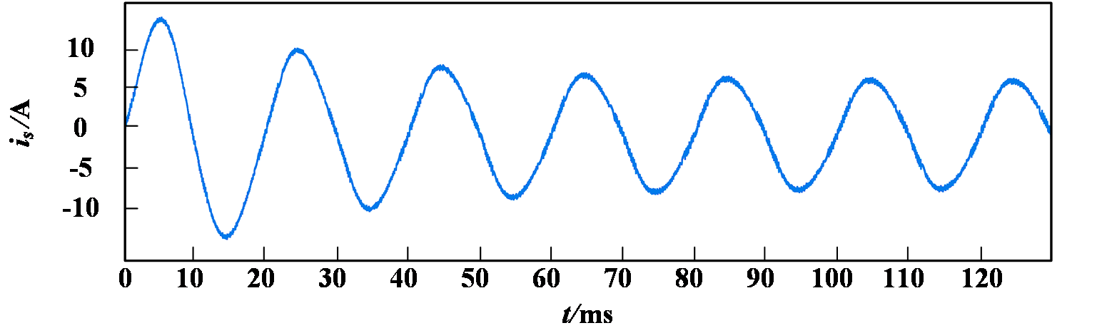
(a) Grid-side current waveform
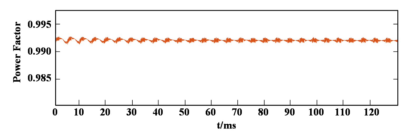
(b) Grid-side input power factor
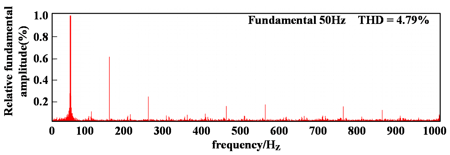
(c) Spectral analysis of grid-side current
Figure 6: Simulation results of single-neuron PI control strategy
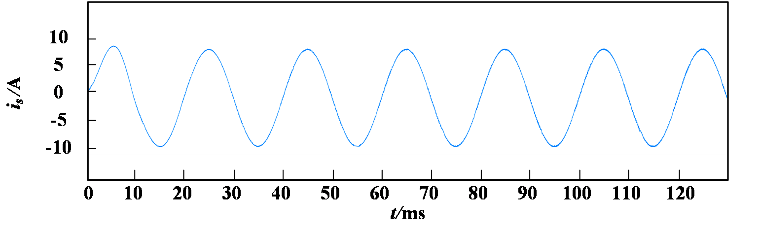
(a) Grid-side current waveform
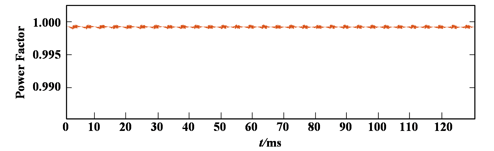
(b) Grid-side input power factor
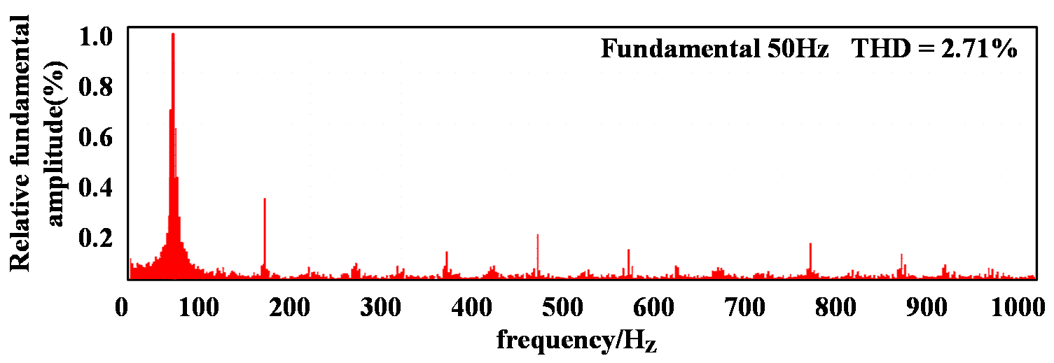
(c) Spectral analysis of grid-side current
Figure 7: Simulation results of the proposed control strategy
To validate the dynamic response capability of the proposed control strategy, Fig. 8 and Fig. 9 respectively illustrate simulation results for traditional and proposed control strategies under a load decrease from full load to half load. Under traditional control, \( {u_{o}} \) overshoot exceeds 35 V with a settling time around 80 ms, indicating poor dynamic performance. In contrast, with the proposed control method, \( {u_{o}} \) reaches the new steady-state within 15 ms, effectively tracking the reference voltage. The maximum voltage fluctuation throughout this process is limited to 13 V, and the grid-side current rapidly stabilizes.
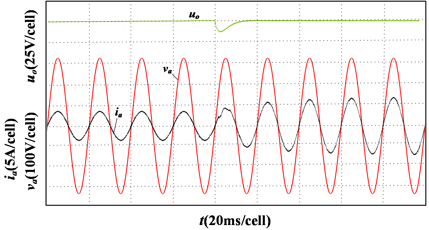
Figure 8: Simulation results of full load decrease to half load under the proposed control strategy
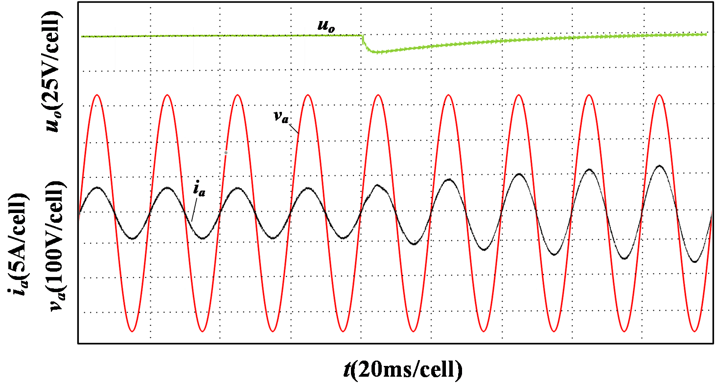
Figure 9: Simulation results of full load decrease to half load under traditional control strategy
5. Conclusion
This paper analyzed the mathematical model of a single-phase VSR-PWM in the d-q rotating coordinate system. In the loop design, incorporating a reinforcement learning-based upper-layer algorithm in the outer loop significantly improved the dynamic response of the single-neuron PI controller, effectively mitigating DC-side voltage overshoot during sudden load variations. Furthermore, the grid-side current THD and system power factor were improved. Through comparative analysis with simulations using the single-neuron PI control strategy, the following conclusions are drawn:
(1) The proposed outer-loop control strategy enhances system performance, achieving stable operation at unity power factor under varying load conditions. Both current THD and power factor are significantly improved, demonstrating that the enhanced outer-loop controller contributes to more stable inner-loop current control.
(2) The improved outer-loop controller effectively enhances the system's dynamic response. When abrupt load changes occur, either increasing or decreasing, the DC-side output voltage rapidly recovers to the set reference value, effectively suppressing voltage overshoot.
References
[1]. Zhang, X., & Zhang, C. W. (2012). PWM rectifiers and their control. Beijing: China Machine Press.
[2]. Zhang, J. W., Yu, H. T., & Wang, Y. C. (2020). SVPWM hysteresis current rectifier control based on permanent magnet linear motor. Micromotors, 53(06), 42–47. https://doi.org/10.15934/j.cnki.micromotors.2020.06.009
[3]. Zhou, J., Liao, D. C., Cai, H. F., et al. (2023). Research on fuzzy multiple PR control strategy for single-phase PWM rectifiers [Journal/OL]. Journal of Power Supply, 1–11. Retrieved February 20, 2025, from http://kns.cnki.net/kcms/detail/12.1420.TM.20230414.2007.010.html
[4]. He, L. P., Guo, Q., Xiao, H. H., et al. (2024). Improved deadbeat control of current-type PWM rectifier with load feedforward compensation. Transactions of China Electrotechnical Society, 39(02), 501–513. https://doi.org/10.19595/j.cnki.1000-6753.tces.221955
[5]. Yuan, Y. S., & Mao, K. X. (2020). Design of controller and improvement of dynamic characteristics for single-phase PWM rectifier. Journal of Electric Machines and Control, 24(05), 34–42. https://doi.org/10.15938/j.emc.2020.05.005
[6]. Li, J. H., & Wu, A. G. (2021). Control strategy of single-phase LCL-type PWM rectifier based on discrete reaching law and deadbeat double-loop structure. Transactions of China Electrotechnical Society, 36(06), 1290–1303. https://doi.org/10.19595/j.cnki.1000-6753.tces.200100
[7]. Wu, M. J., Sun, L., Wu, X. Q., et al. (2025). Redundant sampling and drive control strategy based on phase current reconstruction of permanent magnet motor [Journal/OL]. Journal of Electrical Engineering, 1–10. Retrieved March 28, 2025, from http://kns.cnki.net/kcms/detail/10.1289.TM.20250225.1845.004.html
[8]. Wang, Y. F., Wang, H. Y., & Wu, J. H. (2025). AC voltage amplitude detection method based on improved second-order generalized integrator. Science Technology and Engineering, 25(03), 1093–1101.
[9]. Yu, F. S., Liu, G. F., Zhang, H. W., et al. (2016). Research on feedforward decoupling control strategy for single-phase PWM rectifier. Power Supply Technologies, 40(10), 2068–2070.
[10]. Wang, Z. H., Cai, H. F., Liao, D. C., et al. (2018). Research on passive control of single-phase PWM rectifier based on rotating coordinate transformation. Modern Electronic Technology, 41(22), 83–87, 91. https://doi.org/10.16652/j.issn.1004-373x.2018.22.021
[11]. Xue, J. X., & He, X. (2021). Experimental study on AC electronic load simulation based on rotating coordinate transformation. Electrical Measurement & Instrumentation, 58(07), 44–48. https://doi.org/10.19753/j.issn1001-1390.2021.07.006
[12]. Guo, Q., Zhou, C. L., & Li, S. (2022). Multi-loop control strategy for DC-side voltage of current-source PWM rectifier. Transactions of China Electrotechnical Society, 37(08), 2051–2063. https://doi.org/10.19595/j.cnki.1000-6753.tces.210274
[13]. Guo, Q., He, L. P., Xiao, H. H., et al. (2023). A control method for suppressing DC-side voltage fluctuation in current-type PWM rectifier. Chinese Journal of Scientific Instrument, 44(06), 313–324. https://doi.org/10.19650/j.cnki.cjsi.J2311077
[14]. Xia, T., Liu, L., Zhang, Y. F., et al. (2024). Voltage control of three-phase PWM rectifier using improved single-neuron PI. Electric Drive, 54(05), 20–25. https://doi.org/10.19457/j.1001-2095.dqcd24368
[15]. Hu, C. L. (2022). Research on PWM rectifier control method based on single-neuron adaptive algorithm. Machinery & Electronics, 40(10), 20–24.
[16]. Dai, Y. X., & Cui, C. G. (2023). Control strategy of Boost converter based on deep reinforcement learning. Journal of System Simulation, 35(05), 1109–1119. https://doi.org/10.16182/j.issn1004731x.joss.22-0101
Cite this article
Wang,L. (2025). Reinforcement Learning-Based PI Control Strategy for Single-Phase Voltage Source PWM Rectifier. Applied and Computational Engineering,161,1-10.
Data availability
The datasets used and/or analyzed during the current study will be available from the authors upon reasonable request.
Disclaimer/Publisher's Note
The statements, opinions and data contained in all publications are solely those of the individual author(s) and contributor(s) and not of EWA Publishing and/or the editor(s). EWA Publishing and/or the editor(s) disclaim responsibility for any injury to people or property resulting from any ideas, methods, instructions or products referred to in the content.
About volume
Volume title: Proceedings of CONF-MSS 2025 Symposium: Automation and Smart Technologies in Petroleum Engineering
© 2024 by the author(s). Licensee EWA Publishing, Oxford, UK. This article is an open access article distributed under the terms and
conditions of the Creative Commons Attribution (CC BY) license. Authors who
publish this series agree to the following terms:
1. Authors retain copyright and grant the series right of first publication with the work simultaneously licensed under a Creative Commons
Attribution License that allows others to share the work with an acknowledgment of the work's authorship and initial publication in this
series.
2. Authors are able to enter into separate, additional contractual arrangements for the non-exclusive distribution of the series's published
version of the work (e.g., post it to an institutional repository or publish it in a book), with an acknowledgment of its initial
publication in this series.
3. Authors are permitted and encouraged to post their work online (e.g., in institutional repositories or on their website) prior to and
during the submission process, as it can lead to productive exchanges, as well as earlier and greater citation of published work (See
Open access policy for details).
References
[1]. Zhang, X., & Zhang, C. W. (2012). PWM rectifiers and their control. Beijing: China Machine Press.
[2]. Zhang, J. W., Yu, H. T., & Wang, Y. C. (2020). SVPWM hysteresis current rectifier control based on permanent magnet linear motor. Micromotors, 53(06), 42–47. https://doi.org/10.15934/j.cnki.micromotors.2020.06.009
[3]. Zhou, J., Liao, D. C., Cai, H. F., et al. (2023). Research on fuzzy multiple PR control strategy for single-phase PWM rectifiers [Journal/OL]. Journal of Power Supply, 1–11. Retrieved February 20, 2025, from http://kns.cnki.net/kcms/detail/12.1420.TM.20230414.2007.010.html
[4]. He, L. P., Guo, Q., Xiao, H. H., et al. (2024). Improved deadbeat control of current-type PWM rectifier with load feedforward compensation. Transactions of China Electrotechnical Society, 39(02), 501–513. https://doi.org/10.19595/j.cnki.1000-6753.tces.221955
[5]. Yuan, Y. S., & Mao, K. X. (2020). Design of controller and improvement of dynamic characteristics for single-phase PWM rectifier. Journal of Electric Machines and Control, 24(05), 34–42. https://doi.org/10.15938/j.emc.2020.05.005
[6]. Li, J. H., & Wu, A. G. (2021). Control strategy of single-phase LCL-type PWM rectifier based on discrete reaching law and deadbeat double-loop structure. Transactions of China Electrotechnical Society, 36(06), 1290–1303. https://doi.org/10.19595/j.cnki.1000-6753.tces.200100
[7]. Wu, M. J., Sun, L., Wu, X. Q., et al. (2025). Redundant sampling and drive control strategy based on phase current reconstruction of permanent magnet motor [Journal/OL]. Journal of Electrical Engineering, 1–10. Retrieved March 28, 2025, from http://kns.cnki.net/kcms/detail/10.1289.TM.20250225.1845.004.html
[8]. Wang, Y. F., Wang, H. Y., & Wu, J. H. (2025). AC voltage amplitude detection method based on improved second-order generalized integrator. Science Technology and Engineering, 25(03), 1093–1101.
[9]. Yu, F. S., Liu, G. F., Zhang, H. W., et al. (2016). Research on feedforward decoupling control strategy for single-phase PWM rectifier. Power Supply Technologies, 40(10), 2068–2070.
[10]. Wang, Z. H., Cai, H. F., Liao, D. C., et al. (2018). Research on passive control of single-phase PWM rectifier based on rotating coordinate transformation. Modern Electronic Technology, 41(22), 83–87, 91. https://doi.org/10.16652/j.issn.1004-373x.2018.22.021
[11]. Xue, J. X., & He, X. (2021). Experimental study on AC electronic load simulation based on rotating coordinate transformation. Electrical Measurement & Instrumentation, 58(07), 44–48. https://doi.org/10.19753/j.issn1001-1390.2021.07.006
[12]. Guo, Q., Zhou, C. L., & Li, S. (2022). Multi-loop control strategy for DC-side voltage of current-source PWM rectifier. Transactions of China Electrotechnical Society, 37(08), 2051–2063. https://doi.org/10.19595/j.cnki.1000-6753.tces.210274
[13]. Guo, Q., He, L. P., Xiao, H. H., et al. (2023). A control method for suppressing DC-side voltage fluctuation in current-type PWM rectifier. Chinese Journal of Scientific Instrument, 44(06), 313–324. https://doi.org/10.19650/j.cnki.cjsi.J2311077
[14]. Xia, T., Liu, L., Zhang, Y. F., et al. (2024). Voltage control of three-phase PWM rectifier using improved single-neuron PI. Electric Drive, 54(05), 20–25. https://doi.org/10.19457/j.1001-2095.dqcd24368
[15]. Hu, C. L. (2022). Research on PWM rectifier control method based on single-neuron adaptive algorithm. Machinery & Electronics, 40(10), 20–24.
[16]. Dai, Y. X., & Cui, C. G. (2023). Control strategy of Boost converter based on deep reinforcement learning. Journal of System Simulation, 35(05), 1109–1119. https://doi.org/10.16182/j.issn1004731x.joss.22-0101