


1. Introduction
Shield tunneling method is widely used in tunnel construction because of its technical characteristics of safety, stability and high efficiency [1,2]. With the rapid development of China's high-speed railway, there are an increasing number of projects for ultra-large diameter shield tunnels to underpass the existing railway roadbed [3-5]. Most high-speed railway lines do not have underpenetrating areas, and under penetration of shield tunnels is mostly carried out in the underlying layer, which will cause disturbance to the surrounding soil, and then induce formation loss and soil consolidation settlement. Ballastless track is generally adopted in high-speed railway, which has high requirements for rail deformation. Soil disturbance caused by shield tunneling will reduce the bearing capacity of the upper railway roadbed and increase the irregularity of the track. If it is not properly controlled, it will seriously affect the stability and safety of high-speed railway operation. Therefore, it is very important to take reliable protection measures for railway subgrade reinforcement.
In view of the problem of shield tunneling underpass the existing railway, engineering scholars have carried out the research on settlement mechanism and reinforcement measures. Through field monitoring and numerical simulation, Huang et al.[6] revealed the settlement deformation law of shield tunneling underpass multi-line railway roadbed in soft soil area, and verified the effectiveness of the sleeve valve pipe grouting reinforcement scheme. Relying on a project of Nanjing Metro, Pang[7] reserved the construction conditions of railway double tracks in the later stage by using the "pile + plate" reinforcement method. Sun et al.[8] explored the effectiveness of bag grouting as an active control measure for settlement of high-speed railway foundation based on numerical simulation. At present, the reinforcement of the existing high railway foundation is mainly carried out by grouting[9], and most of the construction technologies such as sleeve valve grouting, segmented grouting and extensive grouting are adopted. The construction period is long, the cost is high, and the grouting effect is unstable. Especially when the ultra-large diameter shield tunneling penetrates the water-rich soft soil layer, the groundwater fluidity is strong, and extensive grouting is difficult to make the grouting materials play a role in the predetermined position. The slurry is easy to be diluted or lost, which reduces the grouting effect, makes the subgrade reinforcement not reach the design strength, and then causes accidents and threatens the project safety [10-12].
The Suzhou East Tunnel project is located in Suzhou Industrial Park and Wuzhong District, with a length of 13,026 m. It enters the ground from the north side of Beijing-Shanghai express railway. During the construction process, a number of existing railways were underpassed. Based on the practical application of engineering, this paper analyzes the deep-hole grouting reinforcement technology in the directional control area of the surface to ensure that the ultra-large diameter shield in the soft soil layer can safely underpass the existing high-speed railway.
2. Project overview
2.1. Overview of the existing railway line
The Suzhou East Tunnel shield section has an outer diameter of 14.3 m, an inner diameter of 13.1 m and a ring width of 2.0 m. It is designed as a single-hole double-track tunnel with an overall longitudinal slope of "W" shape. The tunnel has a maximum buried depth of 58 m and a maximum longitudinal slope of ±25‰, and mainly passes through silty clay, silt and silt layers.
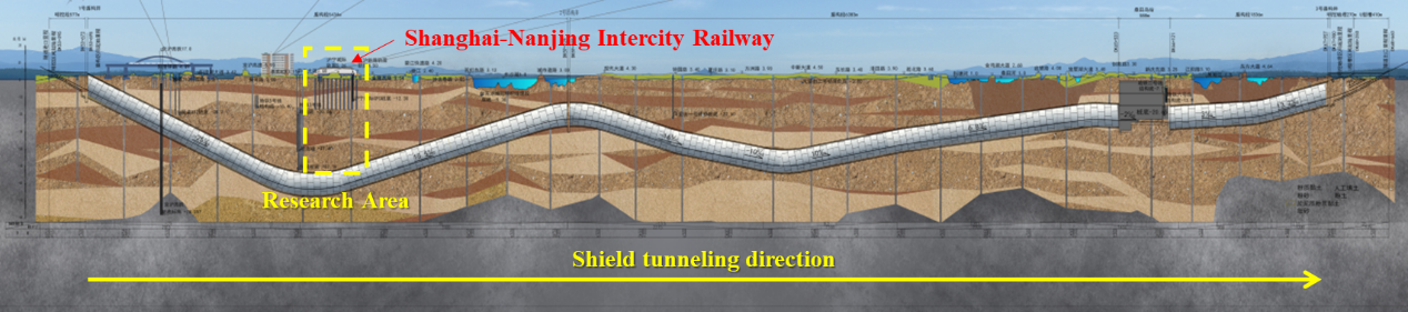
Figure 1: The Suzhou East Tunnel project profile
During the construction of Suzhou East Tunnel, a number of sensitive traffic facilities such as high-speed railways, high-speed railways, expressways and subway lines were be underpassed, especially the Shanghai-Nanjing Intercity Railway. The Shanghai-Nanjing Intercity Railway, China's busiest high-speed rail line, is an intercity passenger line connecting Shanghai and Nanjing, two major cities in East China. The operating mileage of the left plane intersection of Shanghai-Nanjing Intercity line and Suzhou East Tunnel line is K68+175, and the plane of the crossing section of Shanghai-Nanjing Intercity line is a straight section, and the longitudinal slope of the line is 0.5‰. The underpass section is the ballastless track subgrade section, and the subgrade height is 2.6m. The surface thickness of subgrade bed is 0.4m. Fill graded gravel; The bottom layer of the foundation bed is 2.3m thick, and group A and B fillers are used. The subgrade foundation is reinforced with CFG piles, with pile diameter of 0.5 m, pile spacing of 1.8 m, pile length of 13.50 m and square arrangement. CFG pile top raft is made of C30 reinforced concrete, 0.5 m thick, with 0.2 m gravel cushion.
2.2. Engineering geology and hydrogeology
The main strata in the tunnel site area are the Quaternary Holocene and Upper Pleistocene lacustrine deposits, Marine deposits, littoral - swamp deposits of silty clay, silty clay, silt, fine sand, etc. The section of the shield mainly encounters silty clay, silt and silty sand layers, and some sections encounter silty clay layers. Silty clay has low strength and is soft to plastic, which is easy to produce shear failure and lateral deformation. The silt layer of silty clay, soft plastic clay and slightly dense silt has the characteristics of high water content, large pore ratio, low strength, large deformation, high compressibility, thixotropy, rheology, high sensitivity and non-uniformity. The groundwater is mainly quaternary loose rock pore water, distributed in diving and multi-layer confined water, and the buried depth of the groundwater table is 0.5~3 m.
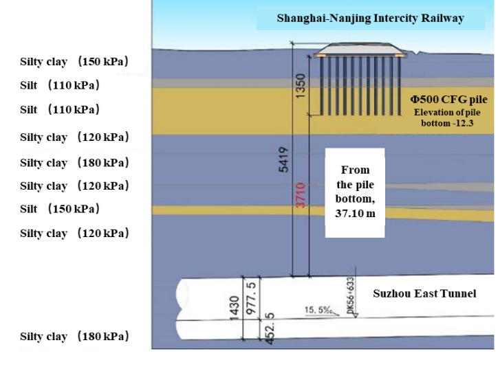
Figure 2: Engineering geological profile of the tunnel crossing
3. Surface directional control area deep hole grouting reinforcement technology
The main adverse geological hazards in the tunnel crossing area are ground settlement. There are deep soft plastic silty clay, slightly saturated silt and silty sand layers above the tunnel crossing area, which have high water content, poor compaction and good permeability. Before shield tunneling, the deep-hole sleeve valve tube is used for grouting reinforcement to improve the soft soil above the tunnel roof, increase the bearing capacity and reduce the subsidence risk of the existing railway roadbed.
3.1. Pre-experiment of grouting technology
It is necessary to conduct pre-experiment before the formal construction operation. Through pre-experiment, parameters such as the ratio of grouting slurry and grouting pressure are determined, and the matching combination of mechanical equipment is determined, which provides a basis for the large-scale drilling and grouting.
3.1.1. Test section position and test hole setting
The test section was selected in the distance DK56+515 ~ DK56+525, located directly above the shield line, 30 meters away from the north side of the Shanghai-Nanjing Intercity downlink line, and 100 meters near the reinforcement area. The same stratum as the grouting reinforcement area was selected for test. A total of 3 test holes were set, with a depth of 52 m and an angle of 83°.
3.1.2. Selection of grouting parameters
Single cement slurry was selected for pre-experiment grouting, and the raw materials were P.O 42.5 grade ordinary Portland cement, common industrial sodium bentonite and water.
The design ratio of shell material in grouting test is water: ash: soil =1.6:1:1, and the optimal ratio is finally determined as water: ash: soil =2.5:1:1.5 through multiple groups of field ratio tests. The shell material mixed under this ratio can be squeezed and crushed by hand after condensation, which meets the requirement that the shell material can be squeezed open in the formation under pressure (grouting pressure), and plays an effective role in sealing holes and conducive to grouting.
Table 1: Test table of shell material ratio for pre-experiment
water: ash: soil | Initial setting time/min | Final setting time/min | Gelling property |
1.6:1:1 | 63 | 720 | The setting time is moderate and the hardness is large |
2:1:1 | 95 | 794 | The setting time is slow and the hardness is larger |
2.5:1:1.5 | 51 | 605 | The setting time is moderate and the hardness is moderate |
3:1:1.5 | 182 | 830 | The setting time is slow and the hardness is poor |
|
|
(a)water: ash: soil =1.6:1:1 | (b)water: ash: soil =2:1:1 |
|
|
(c)water: ash: soil =2.5:1:1.5 | (d)water: ash: soil =3:1:1.5 |
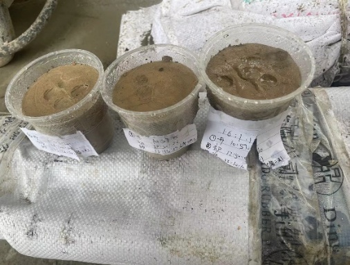
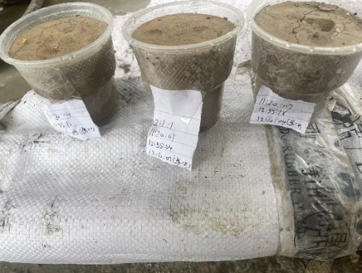
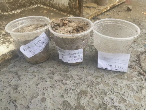
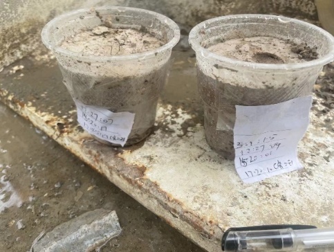
Figure 3: Sampling and observation diagram of different shell material ratio
In order to ensure the grouting effect, the grouting slurry should be prepared according to the principle of thick rather than thin, and the ratio parameter should be pre-tested before grouting construction, and then used on site. Under complex geological conditions, a comprehensive grouting material selection system should be adopted, which is dynamically adjusted in principle according to three criteria: from coarse to fine, from single liquid to double liquid, and from high concentration to low concentration. According to the relevant technical specifications and engineering experience, the design ratio of slurry is water: ash =0.8~1:1. Through the field slurry ratio test, the initial setting time and final setting time of slurry are determined as shown in the following table.
Table 2: Pre-experiment grouting slurry ratio test table
Water-cement ratio | Density/ g/cm3 | Initial setting time | Final setting time | Mean test temperature/℃ |
0.8:1 | 1.63 | 10h 58min | 20h 50min | 25 |
0.9:1 | 1.54 | 12h 25min | 22h 19min | 25 |
1:1 | 1.48 | 14h 43min | 24h 27min | 25 |
|
|
|
(a)Water-cement ratio =0.8:1 | (b)Water-cement ratio =0.9:1 | (c)Water-cement ratio =1:1 |
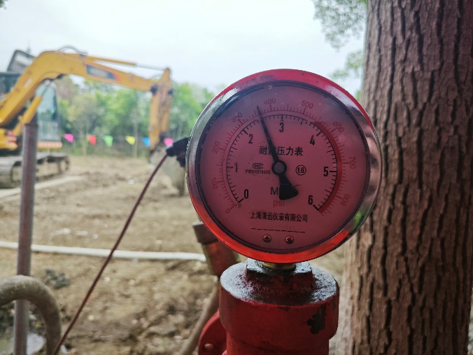
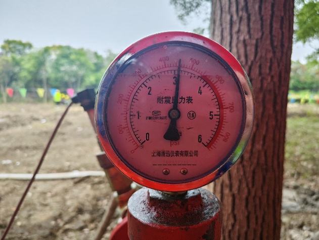
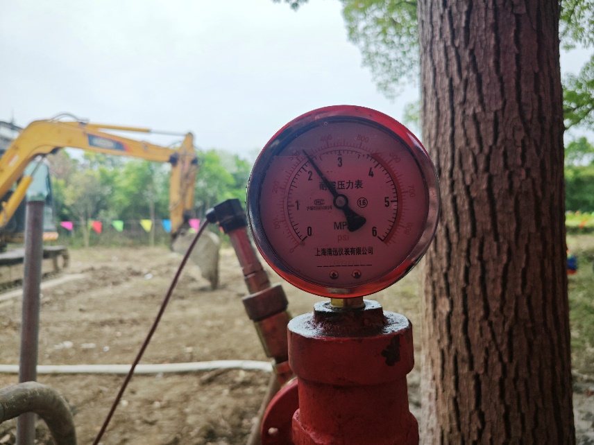
Figure 4: Measured grouting pressure of grout with different water-cement ratio
The water-cement ratio of 0.8:1, 0.9:1 and 1:1 were respectively used for grouting tests in the three test holes. When the water-cement ratio is 0.8:1, the measured grouting pressure is 2.6 MPa. When the water-cement ratio is 0.9:1, the measured grouting pressure is 3 MPa; When the water-cement ratio is 1:1, the measured grouting pressure is 2.3 MPa. For grouting with reinforcement as the main purpose, the final pressure of grouting is generally 2~4 Mpa [13]. Through the test records of the three test holes, the grouting pressure range is determined to be 2~3 MPa.
3.2. Grouting reinforcement scheme of intercity railway foundation
Considering the complex site environmental conditions, the double-side grouting scheme is no longer selected for deep-hole grouting, but the single-side grouting reinforcement scheme is selected. Grouting holes are arranged on the north side of Shanghai-Nanjing Intercity High-speed Railway. Before the shield tunneling, unilateral oblique grouting reinforcement is carried out. The grouting range is 10 m (vertical) ×40 m (vertical Shanghai-Nanjing Intercity direction) ×100 m (along Shanghai-Nanjing Intercity direction) at the top of the shield tunnel, and the surface directional control area deep hole grouting process is adopted. The horizontal inclination angle of the drilling is 42°~83°, the grouting adopts Φ60 mm PVC sleeve valve pipe, and the drilling adopts Φ146 casing to drill the grouting hole, so as to prevent the ground settlement in the drilling project from affecting the operation of the existing railway. The horizontal spacing of the ground opening hole is 1.7 m, the longitudinal spacing is 0.4 m, the grouting diffusion radius is 1.0 m, the grouting pressure is 2~3 MPa, the grouting material is ordinary Portland cement single slurry and cement water glass double slurry, and the early strength HPC grouting admixture can be added if necessary. The water-cement ratio of ordinary cement single liquid slurry is W:C=0.8~1.1: 1, the water-cement ratio of cement water glass double liquid slurry is W:C=0.8: 1~1.1, and the volume ratio C:S=1: 1. In the process of implementation, the grouting parameters are dynamically adjusted according to the grouting test. Cement water glass double slurry is used in the peripheral hole and ordinary cement single slurry is used in the middle hole.
4. Evaluation of application effect of grouting reinforcement technology
4.1. P-Q-t curve method
The P-Q-t curve method is used to draw the P-t and Q-t curves of the grouting pressure P and the grouting speed Q recorded in the grouting construction. The P-Q-t curve is analyzed according to geological characteristics, grouting mechanism, equipment performance and grouting parameters, so as to evaluate the grouting effect. As long as the P-t curve in grouting construction shows an upward trend and the Q-t curve a downward trend, the grouting pressure reaches the design final pressure (usually 1~4 MPa) and the grouting speed reaches the design speed (usually 5~10 L/min) at the end of grouting construction, the grouting effect can basically meet the requirements of reinforcement and water plugging [14,15].
In different stages of grouting reinforcement of Shanghai-Nanjing Intercity roadbed, three groups of grouting holes are randomly selected as verification holes, and curves of grouting quantity Q and grouting pressure P changing with grouting time t at different stages are drawn. P-Q-t curves are analyzed to evaluate the grouting effect of deep holes in roadbed.
Type I grouting curve is mainly the performance of the initial stage of grouting reinforcement, as shown in the change curve of hole 3-36 during grouting, the initial grouting pressure at this stage is 0.35 MPa, and the initial grouting speed is 120 L/min. With the progress of grouting, the grouting pressure rises slowly and the grouting rate decreases slightly, but it is not obvious. With the accumulation of the grouting amount, the grouting pressure gradually reached the designed grouting pressure threshold of 2.1 MPa at the end of the grouting in this hole, and the slurry flow rate dropped to the lowest 18.5 L/min.
Type Ⅱ grouting curve is mainly the performance in the middle stage of grouting reinforcement, as shown in the change curve of hole 9-39 during grouting. The initial grouting pressure is 0.68 MPa and the grouting speed is about 100 L/min. With the progress of grouting, the grouting pressure increases at a uniform speed, and the formation suction rate decreases at a uniform speed. When the grouting amount reaches the saturation value of the formation grouting amount, the grouting pressure rises rapidly, reaching the designed grouting pressure threshold of about 2 MPa, and the grouting speed continues to drop to the lowest 25 L/min.
Type Ⅲ grouting curve reflects the middle and late stage of grouting, and the formation is further strengthened through the remaining reinforcement holes. After the reinforcement of the first two grouting stages, the stratum has become dense, as shown in the curve of hole 29-17, the initial grouting pressure is increased to about 1 MPa, and the grouting rate is reduced to about 80 L/min. The grouting pressure threshold is reached after the grouting time is faster, and the grouting rate decreases further than the curves of type I and type Ⅱ. At this stage, the final grouting pressure reaches 3 MPa and the flow velocity drops to the lowest 12.5 L/min.
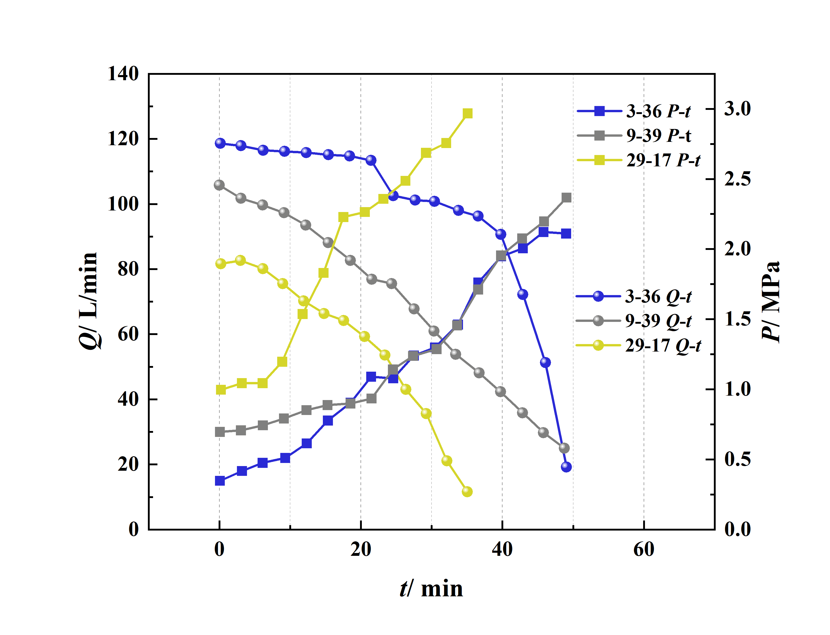
Figure 5: P-Q-t diagram of grouting hole
The grouting in type I stage mainly fills large holes in the formation, the grout meets less resistance, flows relatively fast and diffuses relatively freely, and the grout is mainly reinforced by filling and diffusing. After continuous grouting, the larger cavity in the formation is obviously filled, and the grout further fills the smaller void. The grouting in type Ⅱ stage is mainly extrusion filling of the formation. In the type Ⅲ stage, the grouting slurry further splits the small gap and then extrudes the grouting, making the formation more saturated and denser. It can be seen that the grouting mode of this type is mainly compression-split-extrusion.
4.2. Drilling coring method
The drilling method is a method used in the project with higher grouting requirements, and it is the most intuitive inspection method. After grouting, according to the distribution characteristics of grouting volume, engineering geology and hydrogeology revealed in the grouting process, combined with the analysis of the P-Q-t curve of grouting, the inspection holes are set up for possible weak links of grouting (generally in holes with small grouting volume, holes with large water inflow, and the intersection circle of the final hole). Through the inspection hole observation, coring, grouting test and permeability coefficient measurement, the grouting effect is evaluated. The number of inspection holes should be 3% to 5% of the number of holes and not less than 3, in high pressure rich water stratum grouting water plugging project, the number of inspection holes is recommended to reach 5% to 10%. The higher the grouting requirement, the more inspection holes should be. In principle, the inspection hole shall not use the original grouting hole. The depth of the inspection hole should be less than 1 m in advance drilling, and it is appropriate not to drill through the designed grouting ring. Through the comprehensive analysis of the core rate of the inspection hole, the integrity of the core and the core strength test, the grouting effect is determined. Generally, the coring rate of the inspection hole should reach more than 70%, and the strength should reach more than 0.3 MPa. In this research, after the completion of grouting, according to the time of slurry injection into the formation, select the area where the end time of grouting reaches 28 days, drill the core according to the setting mode of 10 m/inspection hole, and set the core section in the grouting reinforcement body, and the core integrity rate or adoption rate should not be lower than 75% after coring according to the standard.
Through observation, the core on both sides is continuous, complete, columnar, good uniformity, and the adoption rate meets the standard requirements. The lateral compressive strength test results of the test core specimen are 0.57 MPa, 0.58 MPa and 0.62 MPa, and the designed pile strength is 0.50 MPa. The strength of the test specimen is higher than the strength required by the design, which is 4.2 times higher than that of the original stratum. It can be concluded that the foundation strength after grouting has achieved the corresponding strengthening effect.
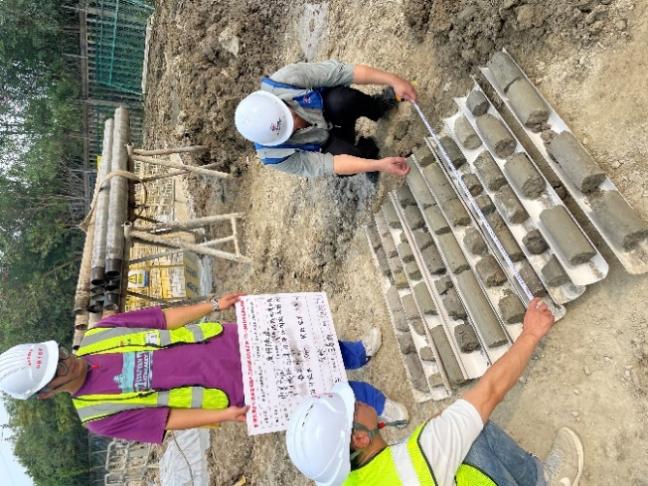
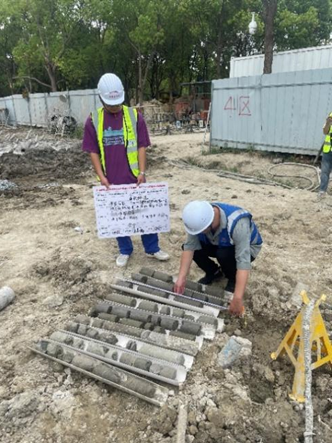
Figure 6: Project site coring situation
Table 3: Test result table of part drilled core specimens
Specimen number | Core size/ mm | Failure load/ kN | Compressive strength of specimen/ MPa | ||
Diameter | Height | Single value | Mean value | ||
1-1 | 99.6 | 99 | 4.36 | 0.56 | 0.57 |
98.9 | 97 | 4.84 | 0.63 | ||
99.1 | 99 | 4.01 | 0.52 | ||
1-2 | 98.7 | 98 | 4.74 | 0.62 | 0.58 |
99.3 | 99 | 4.64 | 0.60 | ||
98.7 | 98 | 3.90 | 0.51 | ||
1-3 | 99.1 | 99 | 4.78 | 0.62 | 0.62 |
98.9 | 98 | 4.99 | 0.65 | ||
99.1 | 98 | 4.55 | 0.59 | ||
4.3. Elastic wave CT method
Cross-hole seismic CT imaging technology, as a fine geophysical exploration technology, transmits seismic waves from the transmitter in the first hole to the second hole and is received by the detector through seismic wave transmission. The data is transmitted to the seismic recorder and stored for post-processing analysis. After superimposing the seismic wave propagation path and then calculating the inversion, the velocity structure imaging of the medium can be obtained. Through comparative analysis of data acquisition and imaging before and after grouting, the grouting effect is judged.
Table 4: Elastic wave CT workload statistics
Section number | Launch /receiving hole number | Seismic wave launch depth/ m | Seismic wave receiving depth/ m | Pitch of holes/ m | Stage |
1 | CT-1~CT-2 | 30~55 | 30~55 | 15 | Before grouting |
2 | CT-2~CT-3 | 30~55 | 30~55 | 15 | |
3 | CT-3~CT-4 | 30~55 | 30~55 | 15 | |
4 | CT-4~CT-5 | 30~55 | 30~55 | 15 | |
5 | CT-5~CT-6 | 30~55 | 30~55 | 15 | |
6 | CT-6~CT-7 | 30~55 | 30~55 | 15 | |
7 | CT-1~CT-2 | 30~55 | 30~55 | 15 | After grouting |
8 | CT-2~CT-3 | 30~55 | 30~55 | 15 | |
9 | CT-3~CT-4 | 30~55 | 30~55 | 15 | |
10 | CT-4~CT-5 | 30~55 | 30~55 | 15 | |
11 | CT-5~CT-6 | 30~55 | 30~55 | 15 | |
12 | CT-6~CT-7 | 30~55 | 30~55 | 15 |
In this study, seven geophysical exploration boreholes (CT-1~CT-7) were arranged in the site of the Shanghai-Nanjing Intercity construction workshop. The CT boreholes were tilted from the direction of Shanghai-Nanjing Intercity Railway outside the line, and were at an angle of 72° to the horizontal plane. The formation in this detection area is mainly silty clay layer, and the wave velocity is generally less than 2700 m/s. Elastic wave CT detection was carried out between two adjacent boreholes. A total of six sets of elastic wave CT were collected before and after grouting respectively, and grouting effect was judged by the data before and after grouting. The specific workload was shown in Table 4.
4.3.1. Results of elastic wave CT before grouting
Before the grouting work was carried out, an elastic wave test was carried out on the test site, and six sets of elastic wave CT tests were completed on site, namely CT-1~CT-2, CT-2~CT-3, CT-3~CT-4, CT-4~CT-5, CT-5~CT-6 and CT-6~CT-7 hole to hole tests. Through the corresponding data processing, the results of the elastic wave CT test section before grouting (inversion wave velocity chromatogram) are as follows:
|
|
(a)CT-1~CT-2 profile | (b)CT-2~CT-3 profile |
|
|
(c)CT-3~CT-4 profile | (d)CT-4~CT-5 profile |
|
|
(e)CT-5~CT-6 profile | (f)CT-6~CT-7 profile |
| |
(g)CT-1~CT-7 stack profile | |
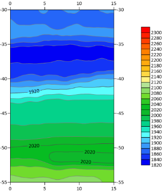
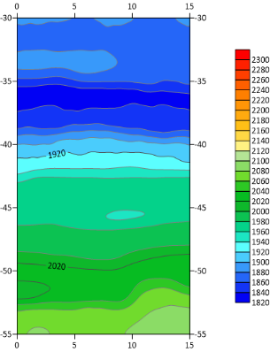
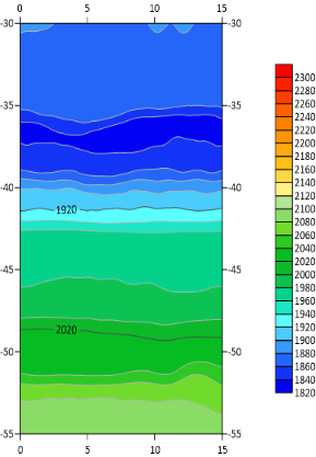
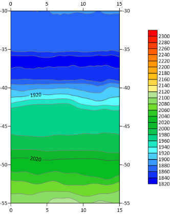
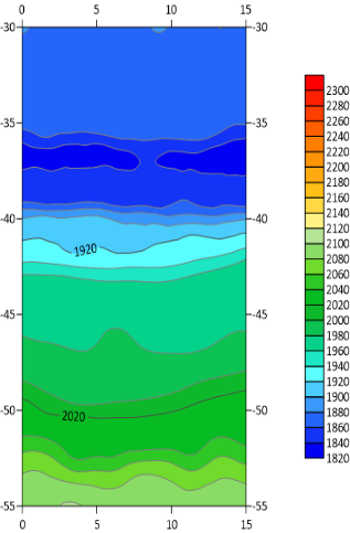
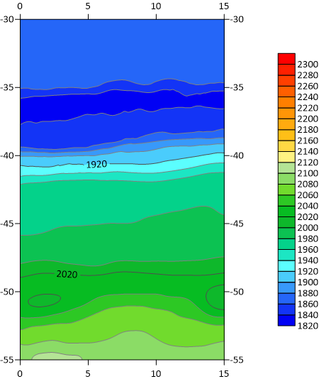
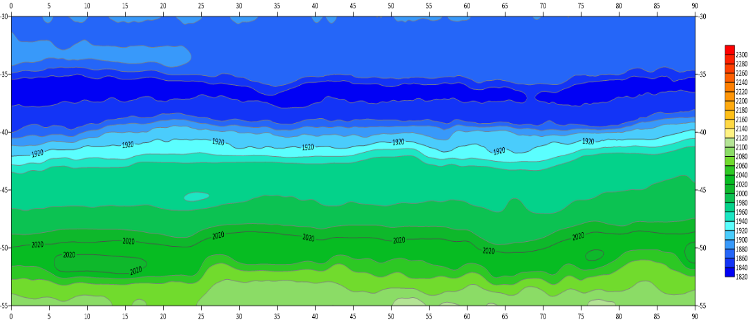
Figure 7: Inversion wave velocity chromatogram of each section before grouting
In the seismic wave velocity chromatogram, red is the relative high speed and light blue is the relative low speed. In this detection area, the seismic wave velocity is generally low, and the seismic wave velocity ranges from 1820 m/s to 2020 m/s. In the range of detection depth, the seismic wave velocity changes little, and the vertical seismic wave velocity gradually increases with the increase of buried depth. The horizontal seismic wave velocity is basically similar, and the velocity value changes little.
4.3.2. Results of elastic wave CT after grouting
Five days after the completion of grouting work, the elastic wave test was carried out on the test site again. CT-1~CT-2, CT-2~CT-3, CT-3~CT-4, CT-4~CT-5, CT-5~CT-6 and CT-6~CT-7 hole tests were carried out on site respectively, and the position and depth of the test section were the same as those before grouting. Through data processing, the results of elastic wave CT test section after grouting (inversion wave velocity chromatogram) are as follows:
|
|
(a)CT-1~CT-2 profile | (b)CT-2~CT-3 profile |
|
|
(c)CT-3~CT-4 profile | (d)CT-4~CT-5 profile |
|
|
(e)CT-5~CT-6 profile | (f)CT-6~CT-7 profile |
| |
(g)CT-1~CT-7 stack profile | |
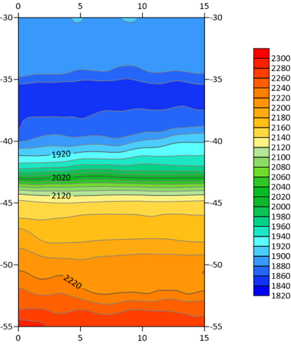
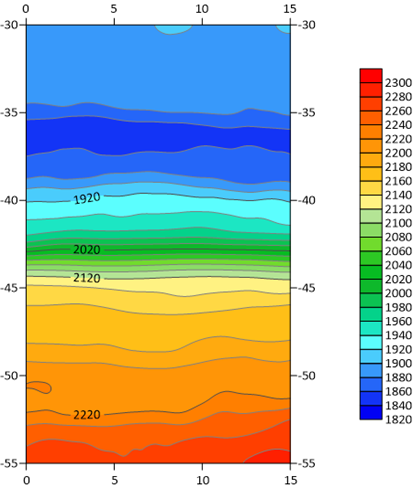
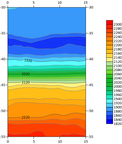
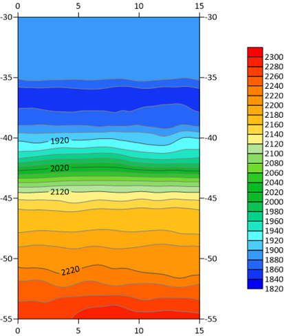
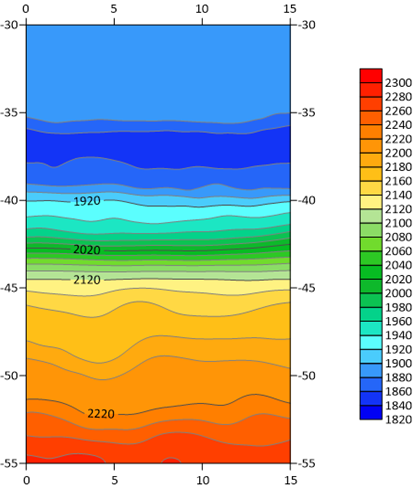
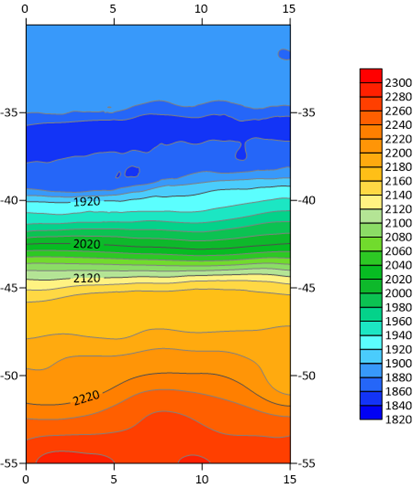
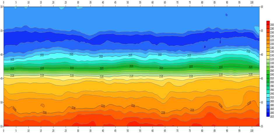
Figure 8: Inversion wave velocity chromatogram of each section after grouting
As can be seen from the figure, within the detection area, the seismic wave velocity ranges from 1820 m/s to 2300 m/s. In the range of detection depth, the vertical seismic wave velocity gradually increases with the increase of buried depth, the horizontal seismic wave velocity is basically similar, and the overall velocity value has little change.
4.3.3. Comparison of elastic wave CT
Based on the comprehensive analysis of the elastic wave CT inversion images and the comparison of the wave velocity changes before and after grouting, it can be seen that the seismic wave velocity basically does not change in the range of 30~42 m in the borehole (28.5~40 m below the surface). In the range of 42~55 m in the borehole (40~52 m below the surface), the seismic wave velocity after grouting is 100 ~ 200 m/s higher than that before grouting. In the grouting area of this survey (41~51 m below the surface), the seismic wave velocity is increased correspondingly, indicating that the pores in the soil body are reduced in this range, and the pores are filled with slurry, and the soil compacted degree is improved and the consolidation degree is increased. The overall fluctuation of seismic wave velocity in the grouting range is small, which indicates that the grout in the soil (or rock mass) is evenly filled and basically covered.
5. Conclusion
With the development of traffic construction, the working conditions of shield tunneling underpass sensitive buildings increase gradually. How to ensure the safety of shield tunneling becomes the focus of engineering. Aiming at the specific engineering problem of shield underpass high railway foundation, this paper relies on the Suzhou East Tunnel underpass Shanghai-Nanjing Intercity High-speed Railway project and adopts grouting reinforcement technology to carry out research as follows:
(1) In order to solve the problem of ground settlement caused by shield tunneling through subgrade in soft soil area and increase rail irregularity, this study adopted surface directional control area deep-hole grouting reinforcement technology before shield tunneling, and grouting reinforcement through deep-hole sleeve valve was carried out to improve the soft soil above the tunnel roof, improve the bearing capacity, and reduce the subsidence risk of existing railway subgrade during shield tunneling.
(2) Before the formal construction of deep-hole grouting reinforcement, pre-experiment is carried out to determine the ratio of grouting slurry, grouting pressure and other parameters, so as to provide data basis for drilling grouting. According to the pre-grouting test, the optimal ratio of shell material is water: ash: soil =2.5:1:1.5. Grouting pressure 2~3 MPa. Ordinary Portland cement single slurry and cement water glass double slurry were used. The water-cement ratio of ordinary cement single slurry was W:C=0.8~1.1:1, the water-cement ratio of cement water glass double slurry was W:C=0.8:1~1.1, and the volume ratio C:S=1:1.
(3) The application effect of grouting reinforcement technology was evaluated by P-Q-t curve method, borehole coring method and elastic wave CT method. At the initial stage of grouting, the slurry mainly fills the large holes in the formation by filling and diffusion. When the design final pressure of the typical holes reaches 2.1 MPa, the grouting speed is 18.5 L/min. In the middle stage, the slurry is squeezed to fill the small space in the formation. When the design final pressure of the typical hole reaches 2 MPa, the grouting speed is 25 L/min. In the later stage, the slurry mainly made the formation more saturated and denser by the way of compression-split-extrusion. When the final grouting pressure of typical holes reached 3 MPa, the flow velocity dropped to the lowest 12.5 L/min. The compressive strength of the test core is 0.57 MPa, 0.58 MPa and 0.62 MPa, which are all higher than the designed pile strength of 0.50 MPa, and the strength of the specimen is 4.2 times higher than that of the original stratum. The change of wave velocity in the area before and after grouting is compared. The seismic wave velocity after grouting is 100 ~ 200 m/s higher than that before grouting, and the soil density is improved. The velocity fluctuation of seismic wave is small, which indicates that the grout filling in rock and soil is uniform.
(4) Combined with the above evaluation methods, the grouting reinforcement effect of Shanghai-Nanjing Intercity Railway roadbed is mutually verified. The grouting effect is good. The slurry splits and solidified the strata above the tunnel and shield crossing, and the bearing capacity of the foundation below the roadbed is improved, achieving the design requirements and the purpose of grouting reinforcement.
References
[1]. Liu X., Ji H., Gan H., et al. Experimental and Numerical Study on Shield Tunnel Strengthened by Ultra-high Performance Concrete. Journal of Tongji University (Natural Science), 2024, 52(11): 1720-1730.
[2]. Han S., Ji Y., Zhao L., et al. Influence Law and Control Measures of Shield Tunnel Undercrossing High Speed Railway Station: Taking the Tianjin Metro Line 4 as an Example of Undercrossing Tianjin West Station. Science Technology and Engineering, 2024, 24(31): 13601-13611.
[3]. Tang Q., Li Y., Peng L., et al. Research on speed limit standard of existing railway traffic under deformation of shield underpass construction. Journal of Railway Science and Engineering, 2022, 19(09): 2700-2708.
[4]. Liu W., Sun K., Dai X., et al. Numerical simulation and field monitoring of influence of metro shield tunnel undercrossing the existing railway frame bridge by long distance. Journal of Railway Science and Engineering, 2022, 19(01): 208-218.
[5]. Xia Q. Research on the Safety Influence of Subway Shield Method Crossing Existing High-speed Railway Frame Bridge. Journal of Railway Engineering Society, 2021, 38(06): 82-86.
[6]. Huang L., Wu G., Tu J. Deformation Law of Shield Tunnel Oblique Under-passing Existing Multi-track Railway Subgrade in Soft Soil Area. Urban Mass Transit, 2023, 26(09): 170-174+179.
[7]. Pang Z. Foundation Reinforcement Design of Metro Shield Tunnel Crossing underneath Existing National Railway. Urban Rapid Rail Transit, 2017, 30(01): 87-93.
[8]. Sun T., Wang A., Zhang Y., et al. Control Effect of Capsuled Grouting on Settlement While Shield Tunneling Underpass High Speed Railway Subgrade. Railway Engineering, 2024, 64(09): 120-126.
[9]. Li Y., Meng Q., Zhang Y., et al. Effect of High Temperature on Mechanical Properties and Microstructure of HSFCM. Journal of Marine Science and Engineering, 2023; 11(4): 721.
[10]. Xing T., Liu H., Zheng J., et al. Study on the Effect of Anchor Cable Prestress Loss on Foundation Stability. Applied Sciences, 2024, 14(11): 490.
[11]. Li X., Liu W., Xu C., et al. Explainable machine learning-based prediction model for dynamic resilient modulus of subgrade soils. Transportation Geotechnics, 2024, 49: 101415.
[12]. Zhang H., Liu T., Cui Y., et al. Experimental study on the deterioration mechanisms of physical and mechanical properties of red sandstone after thermal-acid coupling treatment. Construction and Building Materials, 2024, 455: 139106.
[13]. Zhang M., Peng F. Underground Works Grouting Technology. Beijing: Geology Press, 2008: 121.
[14]. Guan X. Construction Technology of Curtain Grouting in Half Section of Tunnel. Science Technology and Engineering, 2021, 21(34): 14798-14804.
[15]. Li X. Study on the Grouting Treatment Technology of Highway Tunnel Pass through Filling Karst Cave. Modern Transportation Technology, 2014, 11(01): 51-53+64.
Cite this article
Wu,K. (2025). Research on Grouting Reinforcement Technology and Application of Ultra-Large Diameter Shield Tunneling Underpasses Existing Railway in Soft Soil Layer. Applied and Computational Engineering,159,169-182.
Data availability
The datasets used and/or analyzed during the current study will be available from the authors upon reasonable request.
Disclaimer/Publisher's Note
The statements, opinions and data contained in all publications are solely those of the individual author(s) and contributor(s) and not of EWA Publishing and/or the editor(s). EWA Publishing and/or the editor(s) disclaim responsibility for any injury to people or property resulting from any ideas, methods, instructions or products referred to in the content.
About volume
Volume title: Proceedings of the 5th International Conference on Materials Chemistry and Environmental Engineering
© 2024 by the author(s). Licensee EWA Publishing, Oxford, UK. This article is an open access article distributed under the terms and
conditions of the Creative Commons Attribution (CC BY) license. Authors who
publish this series agree to the following terms:
1. Authors retain copyright and grant the series right of first publication with the work simultaneously licensed under a Creative Commons
Attribution License that allows others to share the work with an acknowledgment of the work's authorship and initial publication in this
series.
2. Authors are able to enter into separate, additional contractual arrangements for the non-exclusive distribution of the series's published
version of the work (e.g., post it to an institutional repository or publish it in a book), with an acknowledgment of its initial
publication in this series.
3. Authors are permitted and encouraged to post their work online (e.g., in institutional repositories or on their website) prior to and
during the submission process, as it can lead to productive exchanges, as well as earlier and greater citation of published work (See
Open access policy for details).
References
[1]. Liu X., Ji H., Gan H., et al. Experimental and Numerical Study on Shield Tunnel Strengthened by Ultra-high Performance Concrete. Journal of Tongji University (Natural Science), 2024, 52(11): 1720-1730.
[2]. Han S., Ji Y., Zhao L., et al. Influence Law and Control Measures of Shield Tunnel Undercrossing High Speed Railway Station: Taking the Tianjin Metro Line 4 as an Example of Undercrossing Tianjin West Station. Science Technology and Engineering, 2024, 24(31): 13601-13611.
[3]. Tang Q., Li Y., Peng L., et al. Research on speed limit standard of existing railway traffic under deformation of shield underpass construction. Journal of Railway Science and Engineering, 2022, 19(09): 2700-2708.
[4]. Liu W., Sun K., Dai X., et al. Numerical simulation and field monitoring of influence of metro shield tunnel undercrossing the existing railway frame bridge by long distance. Journal of Railway Science and Engineering, 2022, 19(01): 208-218.
[5]. Xia Q. Research on the Safety Influence of Subway Shield Method Crossing Existing High-speed Railway Frame Bridge. Journal of Railway Engineering Society, 2021, 38(06): 82-86.
[6]. Huang L., Wu G., Tu J. Deformation Law of Shield Tunnel Oblique Under-passing Existing Multi-track Railway Subgrade in Soft Soil Area. Urban Mass Transit, 2023, 26(09): 170-174+179.
[7]. Pang Z. Foundation Reinforcement Design of Metro Shield Tunnel Crossing underneath Existing National Railway. Urban Rapid Rail Transit, 2017, 30(01): 87-93.
[8]. Sun T., Wang A., Zhang Y., et al. Control Effect of Capsuled Grouting on Settlement While Shield Tunneling Underpass High Speed Railway Subgrade. Railway Engineering, 2024, 64(09): 120-126.
[9]. Li Y., Meng Q., Zhang Y., et al. Effect of High Temperature on Mechanical Properties and Microstructure of HSFCM. Journal of Marine Science and Engineering, 2023; 11(4): 721.
[10]. Xing T., Liu H., Zheng J., et al. Study on the Effect of Anchor Cable Prestress Loss on Foundation Stability. Applied Sciences, 2024, 14(11): 490.
[11]. Li X., Liu W., Xu C., et al. Explainable machine learning-based prediction model for dynamic resilient modulus of subgrade soils. Transportation Geotechnics, 2024, 49: 101415.
[12]. Zhang H., Liu T., Cui Y., et al. Experimental study on the deterioration mechanisms of physical and mechanical properties of red sandstone after thermal-acid coupling treatment. Construction and Building Materials, 2024, 455: 139106.
[13]. Zhang M., Peng F. Underground Works Grouting Technology. Beijing: Geology Press, 2008: 121.
[14]. Guan X. Construction Technology of Curtain Grouting in Half Section of Tunnel. Science Technology and Engineering, 2021, 21(34): 14798-14804.
[15]. Li X. Study on the Grouting Treatment Technology of Highway Tunnel Pass through Filling Karst Cave. Modern Transportation Technology, 2014, 11(01): 51-53+64.