


1. Introduction
In the past 70 years, grippers have been developed to a new state; from the plain mechanical robotic clamps to adaptable soft material grippers, they have become increasingly advanced and effective. The grippers and clamps have many specialized divisions; in the aspect of control methods, they can be sorted into hydraulic, pneumatic, string-controlled, and self-contractable. On the other hand, the contracting structures can be classified into mechanical and origami structures. In daily life, people may sometimes lose their gadgets, ornaments, or keys in narrow spaces, such as the grates of drainage. These spaces are often deep and wet; there is also likely to be sludge or water submerging lost items. Traditional tools are of no avail in these situations, and human hands often cannot reach the items due to the thickness of the hand. So, in case this happens, we have built a multifunctional foldable gripper [1] for the specialized use of retrieving lost objects in narrow spaces.
2. Overall design
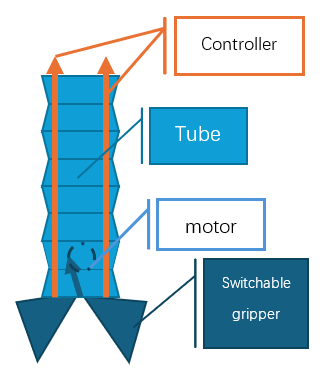
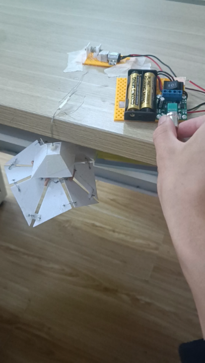
The design of the gripper is a modular configuration; the arm of the gripper is made out of a foldable tube in the pattern of Yoshimura origami, the batteries and control panel are packed at the top of it, and the four sides of it are run through by controlling strings with stoppers attached at each end. The bottom end of the arm is equipped with a motor, which winds the controlling strings of the gripper heads up and down. The electrical wires go inside the tube and contract when the arm is folded. The gripper system is switchable, offering two gripper heads for selection. One mechanical gripper is designed for slim panel-like gadgets, such as a cell phone. Another origami gripper is for the retrieval of cylindrical or prism-like structures. Each of the grippers also consists of stoppers to hold them in place for contraction.(see figure 1)
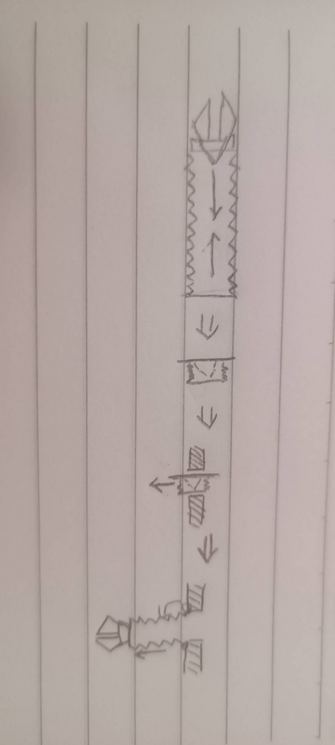
The whole retrieval clamp can be folded separately; the grippers each have their working methods. Thus, they can be inserted into the narrow gaps first; then, the tube arm would fit into the gap in the folded and tilted state. After being lowered into the narrow space, the tube arm extends under its own weight and attaches to the surface of the drainage grates. Therefore, the retrieval clamp can be fully operated to pick objects under the obstacles. Sequences of operation are shown below in figure 2.
3. Conceptual design and analysis
3.1. Clamp structures
3.2. Mechanical clamp
The mechanical gripper consists of two similar components assembled into a scissor-like structure by a rotating hinge, allowing it to fold and fit into narrow gaps. Figure 3 shows the diagram for a single component.
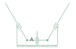
The degree of freedom for this structure is M,
Figure 4 shows how the two components are connected. Component 1 essentially has the A part of Component 2 positioned between its A part and the ground. Both components are free to rotate independently, with their grounds linked together. As a result, the grounds can only rotate, while the A parts can also move vertically.
After being encased in each other, the mechanical claw is formed. To facilitate repositioning after being pulled back for gripping, springs are loaded onto the sliding joints of the A parts.
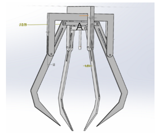
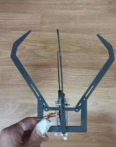
An experimental model is made and presented in Figure 5 below:
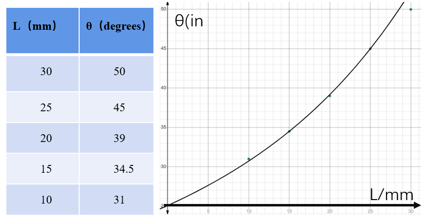
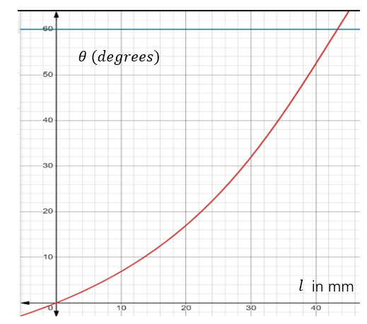
To analyze the folding efficiency of the claws, the relationship of the distance between A and the horizontal part of ground L and the angle between B and the vertical part of ground
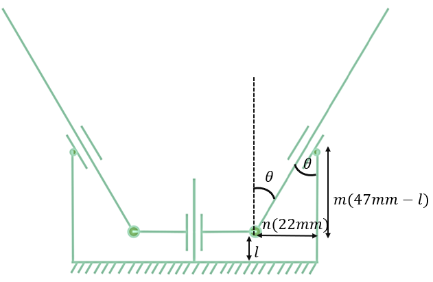
To test and verify the function, data is obtained from measuring the model’s dimensions and angles (fig. 7); these are also plotted as dots on the graph. As the graph suggests, it fits the data points very closely.
3.2.1. Origami clamp
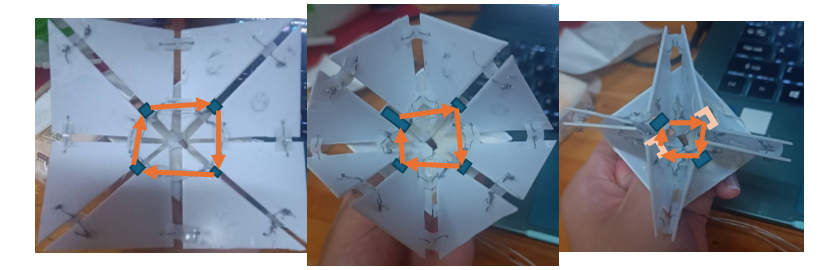
The origami clamp is adapted from the folk toy in southern China, the paper fortuneteller. Fig.8 demonstrates the original pattern of the clamp:
As shown, the structure takes a single-vertex structure, and Tachi’s shortcut formula can obtain the DoF of this original structure [2]:
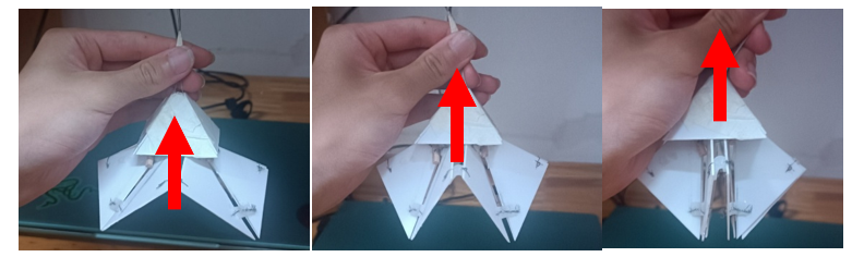
To enable the structure to move through a simple contract & release operation, four mountain creases are connected using stoppers and wires that run through the stoppers to synchronize the contraction (See fig.9).
and the bottom of the structure is equipped with a hollow pyramid with no baseplate to constrain the gripper so that it wouldn’t bend sideways, and its opening angle is limited to a maximum of 180° (see fig.10). As a result, the motion of the structure turns out to be only one way, and the DoF of this structure is reduced to one (supported by the equation below):
Where 3 are the constraints applied by connecting 4 of the independent mountain creases, and 1 is the constraint of the pyramid cap.
The relationship between the angle
In this way, we can obtain Figure 11, which shows the change in θ when l differs.
3.3. Tubular arm
3.3.1. Tube structure
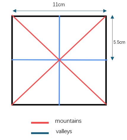
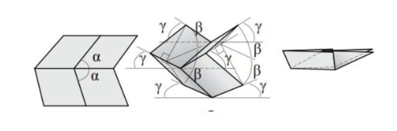
To meet our requirements for foldability, the Tomohiro folding (see figure 12) is chosen to manufacture our tubular robotic arm [3]. By altering the size of the interior angle α, the dihedral angle β, and the angle γ between the crease and the reference plane in the Miura folding unit will also shift. They will follow the equation below [4-7]:
We used a square, foldable, tubular robot arm to fit the selected square gripper jaws. Of the folding units with four, five, or six creases, only the four-crease structure has a single degree of freedom. We made the tube with a “Tomohiro folding,” which is a type of four-crease structure, and the crease design is shown in the figure 13 below [8].
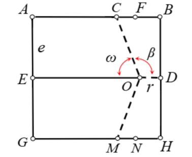
When the point C coincides with the point A,
After acquiring the tube, to realize the miniaturization of the manipulation system, cable control is selected for the robotic arm, which contains four cable strands. Lifting one of the cables causes the robotic arm to contract at one end, allowing it to bend. Lifting all four cables can stow the robotic arm as shown in figure 14.
3.3.2. Motion analysis
The basic unit of the tubular robotic arm is a paper spring structure. Its elastic properties could be analyzed using the following model in figure 15.
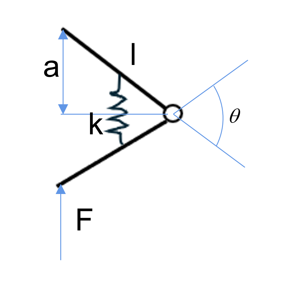
By analyzing this model, the following equations could be derived:
This way, we can obtain the following equation:
As shown in the figure 16, there are four of these units in each layer. Therefore, the equation affecting the deformation of the paper tube is
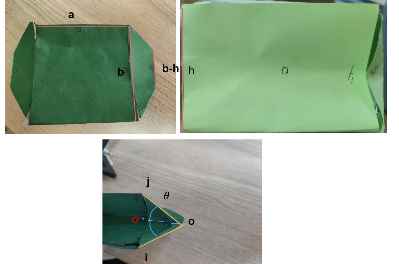
Furthermore, when the paper tube is folded, the perimeter of the centerline position of each layer constantly changes. It is known that the lengths of the horizontal and vertical centerline positions do not change. Therefore, the positions at which the length changes occur are the four inclined parts, the four parts similar to OO’. With a change in angle, the length of OO’ changes.
The perimeter at the centerline is
Figure 17 shows how the perimeter changes with θ.
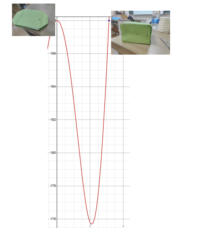
As shown in the above study, the perimeter is equal to the original length of origami paper, and the mechanism is in a stable state when the angle is either 0° or 180° (see figure 18). However, due to the nature of paper springs, the tube cannot automatically transform the angle to either 0° or 180°, so the mechanism cannot be in stable state by itself.
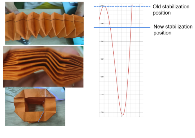
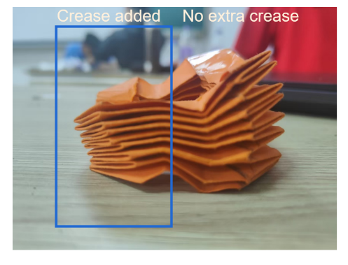
To make the mechanism reach the stable state, a crease is added, as shown in the figure 19. The new crease changes the length of side a, decreasing the total perimeter of the folded paper and changing the stable point of the folded paper tube. This allows the folded paper tube to tighten automatically after adding the crease, which facilitates the retraction of the robotic arm.
4. Construction of prototypes
4.1. Grippers
The mechanical gripper parts are printed out using black resin and assembled by inserting steel pivots into rotating joints (Figure 20). The posts that the A parts slide upon are loaded with thin springs to help reposition the claws. A rubber band and a stopper have been applied to maintain a 90 ° angle between the two grounds once released.
Origami gripper parts are cut out from PVC sheets and connected by silica gel (Figure 21). The stoppers are loaded behind the slit between each mountain crease, and strings are attached from one to another, ultimately merging into a single cord that runs through the top hole on the pyramid cap.
4.2. Tube arm
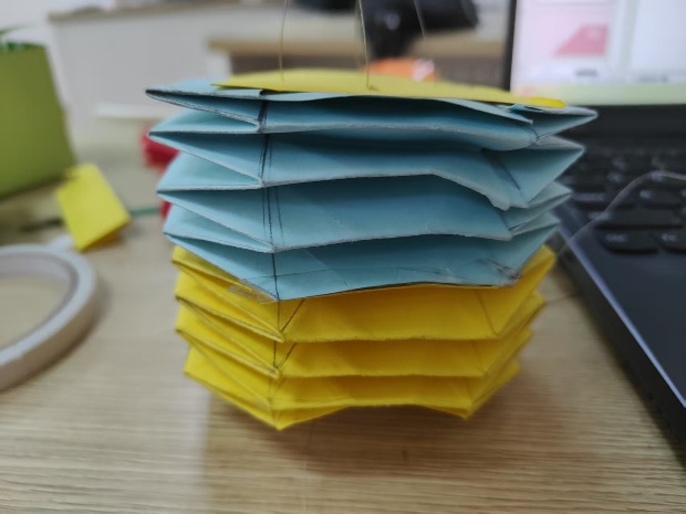
Because folding tubes need to be collapsible and have elasticity at the same time, we chose paper to prototype a tubular robotic arm (Figure 22).
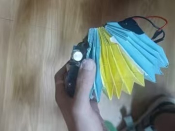
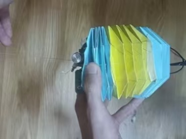
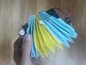
There are four cables in the tubular robotic arm; stretching one of them can achieve the contraction of the robotic arm. In this way, we can gain control over the robotic arm.
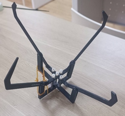
5. Final prototype
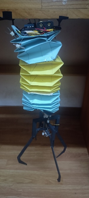
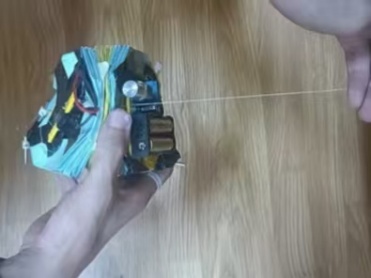
By combining the two parts, we can obtain our final prototype (Figure 23). A motor-powered mini capstan would wind the cord on each of the grippers and make them contract.
6. Conclusion
Conventional lost item retrieval tools often struggle to adapt to narrow environments, such as drain grates, due to their fixed structures and poor adaptability. This makes it difficult to handle items of various shapes and navigate complex, confined spaces. These limitations reduce their retrieval efficiency and stability. To overcome these limitations, this study designed a portable lost item retrieval clamp integrated with a modular system. This design enables efficient and flexible retrieval in narrow environments.
Built on a modular system, the device uses a foldable tubular arm inspired by Yoshimura origami. It is driven by an electric motor-controlled cable system and equipped with interchangeable end effectors: a mechanical clamp for flat objects and an origami-based clamp for cylindrical or prismatic objects. These features allow the device to meet the recovery needs of objects of various shapes. Additionally, structural and mathematical analyses were conducted, including degree-of-freedom calculations and clarification of folding component relationships, to ensure clear system operational logic. A prototype was built and tested to validate the design’s effectiveness. The control system enables compact operation in narrow spaces and adapts to complex recycling scenarios.
Overall, the tested recycling claw modular system is stable and effective, providing a compact, adaptable solution for recovering lost items in confined spaces. However, there are still issues that need to be addressed, such as improving the flexibility of tool interchangeability, enhancing the sensitivity of arm control, and optimizing the balance between material durability and performance. Future efforts will focus on improving fixture interchangeability, enhancing arm control precision, and optimizing materials to improve durability and performance. These efforts will expand the application potential of the system in narrow-space recovery operations and provide new design strategies for similar portable recovery devices.
Acknowledgement
Jiayang Xi and Jinhui Guo contributed equally to this work and should be considered co-first authors.
References
[1]. Nishimura, T., Muryoe, T., Asama, Y., Ikeuchi, H., Toshima, R., & Watanabe, T. (2022). Single-fingered reconfigurable robotic gripper with a folding mechanism for narrow working spaces. IEEE Robotics and Automation Letters, 7(4), 10192-10199.
[2]. Tachi, T. (2010, November). Geometric considerations for the design of rigid origami structures. In Proceedings of the International Association for Shell and Spatial Structures (IASS) Symposium (Vol. 12, No. 10, pp. 458-460). Shanghai, China: Elsevier Ltd.
[3]. Kim, S. J., Lee, D. Y., Jung, G. P., & Cho, K. J. (2018). An origami-inspired, self-locking robotic arm that can be folded flat. Science Robotics, 3(16), eaar2915.
[4]. Tachi, T. (2010). Freeform rigid-foldable structure using bidirectionally flat-foldable planar quadrilateral mesh. In Advances in architectural geometry 2010 (pp. 87-102). Springer, Vienna.
[5]. Tachi, T. (2011). Rigid-foldable thick origami. Origami, 5(5), 253-264.
[6]. Miura, K., & Tachi, T. (2010). Synthesis of rigid-foldable cylindrical polyhedra. Symmetry: Art and Science, 2010, 204-213.
[7]. Tachi, T. (2010). Freeform Variations of Origami. Journal of Geometry and Graphics, 14, 203-215.
[8]. Chen, Y., Lv, W., Li, J., & You, Z. (2017). An extended family of rigidly foldable origami tubes. Journal of Mechanisms and Robotics, 9(2), 021002.
Cite this article
Xi,J.;Guo,J. (2025). Report on a Kind of Portable Object Retrieval Clamp. Applied and Computational Engineering,186,10-24.
Data availability
The datasets used and/or analyzed during the current study will be available from the authors upon reasonable request.
Disclaimer/Publisher's Note
The statements, opinions and data contained in all publications are solely those of the individual author(s) and contributor(s) and not of EWA Publishing and/or the editor(s). EWA Publishing and/or the editor(s) disclaim responsibility for any injury to people or property resulting from any ideas, methods, instructions or products referred to in the content.
About volume
Volume title: Proceedings of CONF-FMCE 2025 Symposium: Semantic Communication for Media Compression and Transmission
© 2024 by the author(s). Licensee EWA Publishing, Oxford, UK. This article is an open access article distributed under the terms and
conditions of the Creative Commons Attribution (CC BY) license. Authors who
publish this series agree to the following terms:
1. Authors retain copyright and grant the series right of first publication with the work simultaneously licensed under a Creative Commons
Attribution License that allows others to share the work with an acknowledgment of the work's authorship and initial publication in this
series.
2. Authors are able to enter into separate, additional contractual arrangements for the non-exclusive distribution of the series's published
version of the work (e.g., post it to an institutional repository or publish it in a book), with an acknowledgment of its initial
publication in this series.
3. Authors are permitted and encouraged to post their work online (e.g., in institutional repositories or on their website) prior to and
during the submission process, as it can lead to productive exchanges, as well as earlier and greater citation of published work (See
Open access policy for details).
References
[1]. Nishimura, T., Muryoe, T., Asama, Y., Ikeuchi, H., Toshima, R., & Watanabe, T. (2022). Single-fingered reconfigurable robotic gripper with a folding mechanism for narrow working spaces. IEEE Robotics and Automation Letters, 7(4), 10192-10199.
[2]. Tachi, T. (2010, November). Geometric considerations for the design of rigid origami structures. In Proceedings of the International Association for Shell and Spatial Structures (IASS) Symposium (Vol. 12, No. 10, pp. 458-460). Shanghai, China: Elsevier Ltd.
[3]. Kim, S. J., Lee, D. Y., Jung, G. P., & Cho, K. J. (2018). An origami-inspired, self-locking robotic arm that can be folded flat. Science Robotics, 3(16), eaar2915.
[4]. Tachi, T. (2010). Freeform rigid-foldable structure using bidirectionally flat-foldable planar quadrilateral mesh. In Advances in architectural geometry 2010 (pp. 87-102). Springer, Vienna.
[5]. Tachi, T. (2011). Rigid-foldable thick origami. Origami, 5(5), 253-264.
[6]. Miura, K., & Tachi, T. (2010). Synthesis of rigid-foldable cylindrical polyhedra. Symmetry: Art and Science, 2010, 204-213.
[7]. Tachi, T. (2010). Freeform Variations of Origami. Journal of Geometry and Graphics, 14, 203-215.
[8]. Chen, Y., Lv, W., Li, J., & You, Z. (2017). An extended family of rigidly foldable origami tubes. Journal of Mechanisms and Robotics, 9(2), 021002.