


1. Introduction
Using sustainable transportation helps reduce carbon emissions, alleviate traffic congestion, and promote a healthier, more environmentally friendly lifestyle. In sustainable mobility, hybrid vehicles are pivotal but limited by unrecaptured energy losses. Unlocking their full potential demands synergizing key technologies: Regenerative braking recovers kinetic energy during deceleration, amplified by mechanical flywheels that store excess energy efficiently for rapid reuse. Waste heat from engines and exhaust long squandered is harnessed via thermoelectric generators and Rankine cycles. Meanwhile, electric turbochargers eliminate lag, optimizing engine performance across speeds to cut inefficient combustion. Integrating these things such as Kinetic Energy Recovery systems (KERS), waste heat reuse, and engine optimization drives unprecedented energy utilization, slashing fuel use and emissions, and accelerating progress toward carbon neutrality. Therefore, we will conduct research on how to significantly enhance overall efficiency.
Pole-changing induction machine PCIMs have been studied for their advantages in torque density, fault tolerance, and wide speed ranges, with research focusing on modeling and winding design [1,2]. Karatzaferi, et al. [3] addresses this by proposing methods to calculate energy during braking and determine optimal braking periods, laying groundwork for maximizing the amount of energy recaptured during braking events. Heydari, et al. [4] develops a low-speed cutoff detection mechanism to identify when regenerative braking becomes ineffective, highlighting the need for solutions to extend efficient braking to lower speed ranges.
Flywheel KERS is investigated here as a mechanical buffer that circumvents the round-trip losses and power-rate limits inherent to electrochemical storage. Earlier foundational work established the principle: Sun et al. [5] employing a 300 m s⁻¹ rim-speed, 0.7 radius-ratio planetary gear set and Ershad et al. [6] using a 20 kr min⁻¹, 12 kg dual-disc transient module showed that torque smoothing, and zero battery transients can be achieved in urban cycles. These prior findings motivate the present study, in which the same two architectures are re-examined under harmonized test conditions to isolate the influence of flywheel inertia, gear ratio and control strategy on overall energy recovery and to quantify the incremental range benefit relative to conventional battery-dominant systems.
The studies develop a thermoelectric-pv hybrid energy system consisting of two thermoelectric generators for use in hybrid electric vehicles. This system is capable of dynamically charging the battery of the hybrid vehicle by converting the heat generated by solar radiation and the hot air expelled into electrical energy [7]. Consequently, this new waste heat recovery system achieved a maximum power output of 350 W under the condition that exhaust gases raised the temperature of the heat pipe evaporator's surface to 170 °C. [8]. And another aspect is that energy harvesting is a science that collects energy from the surrounding environment and converts it into more useful forms of energy (such as electrical energy). This is a prominent and crucial emerging technology that may serve as a solution to ensure the supply of environmental energy and thereby extend the lifespan of low-power electronic devices [9].
Recent studies have explored various methods to enhance the efficiency of waste heat recovery systems, particularly for low-grade heat sources. Jiménez-García et al. (2023) reviewed Organic Rankine Cycle (ORC) configurations and emphasized the benefits of advanced layouts, such as hybrid and recuperative designs, over conventional simple cycles [10]. They also examined trans critical CO₂ power cycles and highlighted the role of cycle architecture, particularly reheating and recuperation, in improving performance at different temperature ranges. In addition, Rodríguez-de Arriba et al. (2022) investigated CO₂-based mixtures and demonstrated their potential to reduce system irreversibility and improve exergy efficiency [11]. These studies collectively indicate that both cycle optimization and the choice of working fluid are critical for improving the performance of low-grade heat recovery systems. The present work aims to build on these insights by evaluating selected approaches under relevant thermal conditions.
Research demonstrates that electric turbochargers significantly improve transient response compared to conventional systems. Katrasnik et al. [4] showed a reduction in the time required to perform a transient power increase for a diesel engine. Similarly, Ibaraki et al. [5] achieved a reduction in response time and an increase in low-speed torque using a motor assist. Furthermore, Millo et al. [6] reported potential fuel consumption reductions in transient-heavy urban cycles. However, these studies primarily present numerical results or specific tested configurations, and a key challenge remains the parasitic energy loss from the electrical power required for motor assistance, which can decrease efficiency gains. Research will mainly focus on exploring solutions like integrated motor-generators acting as both motors and generators to restore energy, reducing this loss and further improving overall system efficiency.
This paper will use overall efficiency as a primary criterion to evaluate and compare several energy recovery methods, with the goal of identifying the most practical and effective solution for capturing and reusing waste energy in automotive vehicles to enhance fuel economy and extend travel range. The analysis will also consider technical feasibility and integration potential within existing vehicle systems.
2. Regenerative breaking
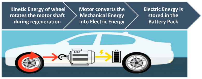
Regenerative braking is an energy recovery technology that converts the kinetic energy generated during vehicle deceleration or braking into storable electrical energy, rather than dissipating it as waste heat through traditional friction braking systems.
Through simulations conducted on a range of vehicle types as shown in Figure 2, the results demonstrate that, under the WLTC driving cycle, this control strategy can reduce energy consumption by 29.5% to 30.3% compared to the same vehicles without regenerative braking capability [12].
Regenerative braking systems not only capture energy that would otherwise be lost during deceleration but also contribute to lower vehicle emissions and reduced brake wear. By conserving fuel and minimizing material degradation, these systems offer financial advantages. Additionally, their implementation supports environmental sustainability and the advancement of renewable energy technologies [13].
In one CTCRDC cycle, serial 2 got back 0.267 kW·h of energy. This was more than serial 1 (0.235 kW·h) and parallel (0.206 kW·h). Serial 2 also did better in terms of axle efficiency (0.4385), battery charge-discharge efficiency (0.8197), and vehicle energy efficiency (16.436 kW·h/100 km). It also had the highest contribution rates: 41.09% for energy transfer efficiency (σr) and 24.63% for driving range (σc). The discussion says serial 2 is better because its regeneration setup is more active. This means it gets back when the car slows down. Better coordination between regenerative and friction braking helps improve energy recovery. The conclusion shows that the proposed evaluation parameters (σr and σc) work well for checking RBS’s contribution. It confirms that serial 2 has the highest regeneration efficiency. These findings can help make regenerative braking systems in EVs better.
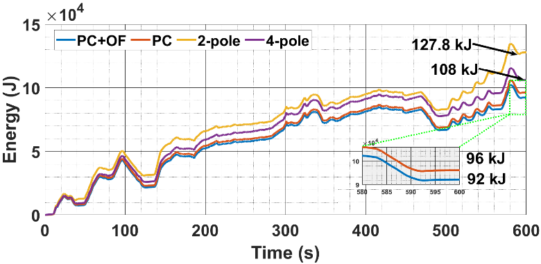
In the US06 drive cycle, we used the combined method of pole changing and over fluxing. This method led to an energy consumption of 92 kJ. It was much lower than the 96 kJ of pole changing alone, the 108 kJ of four-pole mode, and the 127.8 kJ of two-pole mode as shown in Figure 3. Its regenerative efficiency stood at 43.26%. This was higher than the 35.8% of two-pole mode and 34.8% of four-pole mode. Test results also matched simulations, showing a 23.3% reduction in energy use. The discussion found that pole changing can extend the range of constant power. Over fluxing, in turn, can enhance energy capture at lower speeds. This brought the low-speed cutoff down from 670 r/min to 350 r/min. It also balanced torque, speed, and losses effectively. This study shows that combining pole changing with controlled over fluxing improves regenerative braking efficiency. It reduces energy consumption by about 25%. Key outcomes include a longer constant power range, a lower cutoff speed, and better energy recovery. This not only eases "range anxiety" in EVs. It also shows that multiphase pole-changing motors, with such combined techniques, can be a promising option.
In the context of global efforts to promote sustainable transportation methods, promoting the energy efficiency of electric vehicles (EVs) and hybrid electric vehicles (HEVs) has become a key focus of academic research. Among them, regenerative braking systems (RBS) and energy-based path optimization strategies are regarded as crucial means to improve energy efficiency. This study focuses on the influence of vehicle characteristics (such as vehicle weight) and road environment (such as slope changes) on energy consumption performance, aiming to identify the core variables that can be used for energy-saving route planning in navigation systems, thereby addressing the shortcomings of current mainstream navigation systems that generally prioritize travel time or distance while neglecting energy consumption optimization.
To achieve this goal, the research was conducted in the city of Gdynia, Poland. A Mazda MX-30 electric vehicle was selected as the experimental platform as shown in Table 1. During the experiment, the speed and altitude data of the vehicle during driving were collected using a global positioning system device, and four test routes were selected as shown in Table 2.
The research focused on analyzing the effects of different load conditions (respectively 100%, 125% and 150% of the base mass) and changes in road gradients (0%, 100% and 200% of the height variation) on the energy efficiency coefficient (EEC). The research was based on the following premise assumption: Variables such as road gradients and vehicle mass have a significant impact on energy consumption performance. If these variables are incorporated into the navigation algorithm, it is expected to achieve more energy-efficient path selection.
|
Vehicle |
Mass (driver inc.) [kg] |
Power [kW] |
Battery capacity [kWh] |
ηel [%] |
ηreg [%] |
Paux [W] |
|
Mazda MX-30 |
1795 |
107 |
35 |
78 |
61 |
200 |
|
Route No. |
Length [m] |
Av. speed km/h |
SEC [kWh/ (t·100 km)] |
RBSE [kWh/ (t·100 km)] |
Height min [m] |
Height max [m] |
Height differ- ence [m] |
|
1 |
2762 |
16 |
10.7 |
5.3 |
41 |
88 |
20 |
|
2 |
2931 |
26 |
8.5 |
4.5 |
40 |
67 |
0 |
|
3 |
3117 |
35 |
6.6 |
1.9 |
45 |
57 |
–2 |
|
4 |
2891 |
45 |
6.2 |
3.6 |
33 |
59 |
–21 |
3. Mechanical flywheel
A flywheel is a mechanical rotating energy storage device that stores kinetic energy in the form of rotational inertia [17]. The flywheel stores energy as rotational kinetic energy and releases it during acceleration [18]. In contrast to electrochemical batteries, which store energy in chemical form and experience limited charge or discharge rates and degradation under high current pulses, flywheels store energy mechanically in a spinning mass [19]. As shown in the Figure 4 and Figure 5, when applied to electric vehicles, flywheels smooth high power transients during acceleration and braking, lowering peak battery currents and increasing overall energy efficiency [20].
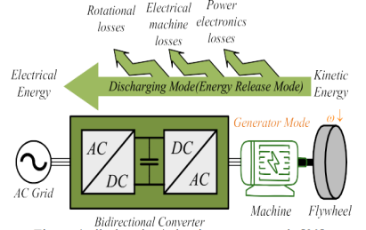
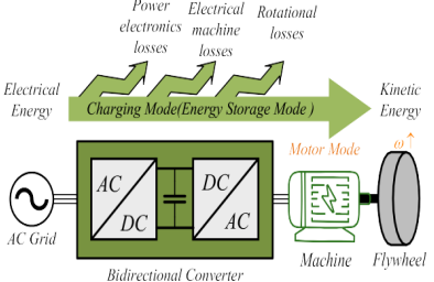
Recovering kinetic energy during vehicle deceleration is one of the important ways to improve the energy efficiency of transportation. Especially for electric and hybrid vehicles, the driving range is still a crucial issue [21]. Conventional battery-based regenerative systems suffer from significant efficiency losses due to chain inefficiencies in energy conversion (mechanical → electrical → chemical) and limited charge acceptance rates during short-duration braking events. Mechanical flywheel energy storage system (FESS) provides an alternative way to store the kinetic energy in form of rotational inertia without involving electrochemical conversion process [20]. This paper aims at investigating the improvement of overall energy recovery efficiency with flywheel-based KERS by comparing with battery dominated system, especially for high power transient braking with less energy conversion.
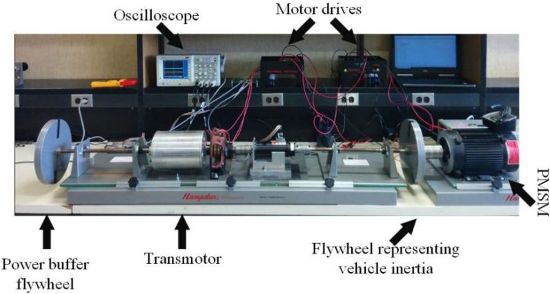
Validate the conjecture by large-quantity experiments, and conduct simulation experiments by constructing physical prototypes as shown in Figure 6. Validate that the net energy exchange between the flywheel and the battery emulator (DC bus capacitor) is zero during vehicle acceleration. The steady DC bus voltage and the measured energy increment validate the minimal cell participation and high mechanical transmission efficiency in practice, to validate the crucial role of the mechanical flywheel in energy recovery. The suggested 4WD electric powertrain with flywheel KERS improves significantly the kinetic energy recovery efficiency by reducing electrical energy conversion losses.
As shown in
Figure 7, the wheel-to-wheel ROR is improved to 0.75 PU compared to 0.36 PU in conventional battery-based systems, when 70% of the braking energy is transferred mechanically to the flywheel with 95% efficiency and only 30% is converted electrically.
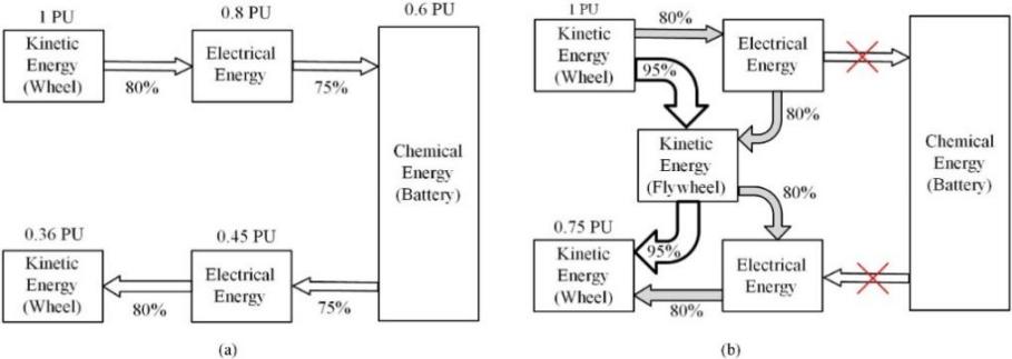


This lessens the dependence on battery power during acceleration or deceleration, allowing for zero-battery usage when flywheel speed is greater than wheel speed (ωFW≥ωW).
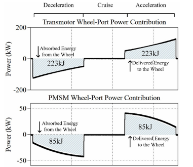
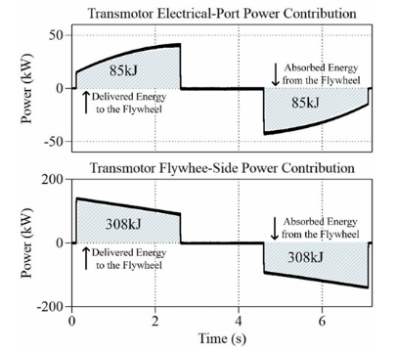
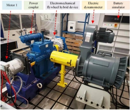
Figure 8 the experimental verification showed that the powertrain can handle 150 kW of mechanical power, three times its electrical rating (50 kW), without overloading any components, thanks to the magnetic clutch function of the Transmotor. Thus, the flywheel system increases the life of the battery by decreasing the number of charge cycles, and improves overall efficiency by 8-10% in urban driving cycles, overcoming the main disadvantages of conventional regenerative braking. The objective of this study was to improve the regenerative braking efficiency of electric vehicles through the design of a non-ultra-high-speed electromechanical flywheel hybrid system based on planetary gears [5], so as to solve the problem of energy loss of the vehicle under the application scenario of frequent urban stop-and-go. The topology of the flywheel unit is optimized such that the speed-regulating motor is connected to the sun gear, the flywheel is connected to the ring gear, and output is to the planetary carrier, which helps maximize torque transmission and minimize mechanical losses. As shown in the Figure 9, the validation conjecture employs a test platform with an electric dynamometer and a battery simulator to mimic the driving cycle in each scenario [5].
The experiment validates the function of the flywheel in smoothing battery power variation under NEDC cycles.
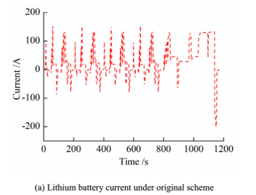
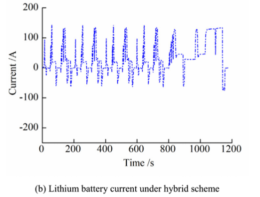
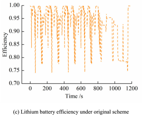
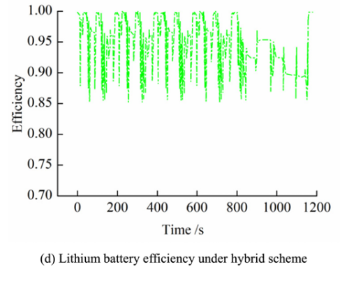
Figure 10, the fluctuation of battery power is mitigated by 53.8% with the buffering of flywheel. The flywheel hybrid system alleviates the peak battery current and changes the motor working area into the high-efficiency zone, as shown in
Figure 11, which leads to an increase in powertrain efficiency by 8.2% (J1015), 5.6% (NEDC) and 4.3% (HWFET). The fast energy buffer of the flywheel decreased 0-100 km/h acceleration time by 18.25%, and reclaimed 2704.62kJ braking energy, which extends driving range by 15.43%. More importantly, the lithium battery becomes 6.7% efficient due to less high-current stress and deferred degradation. The study concluded that the optimized flywheel parameters (300 m/s rim speed, 0.7 radius ratio) balance safety and cost while covering 94% of braking events, making mechanical energy recovery indispensable in improving the efficiency of urban electric vehicles.
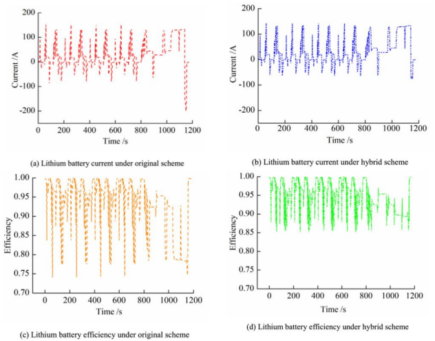
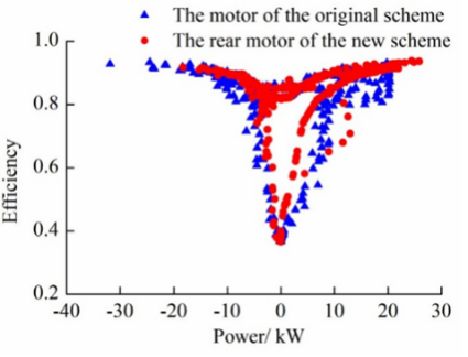
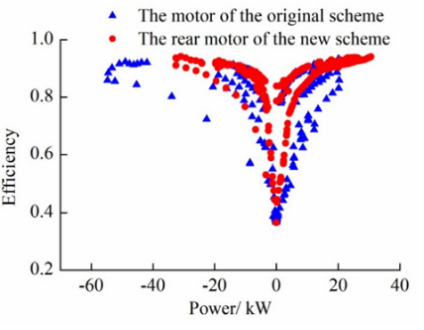
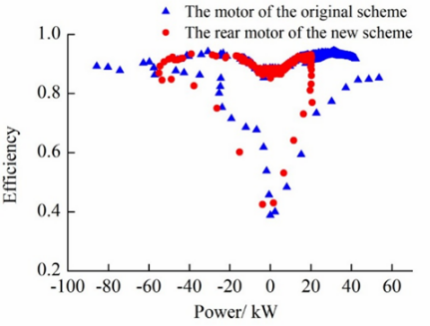
Figure 11. Difference between original and new [5]
4. Thermoelectric
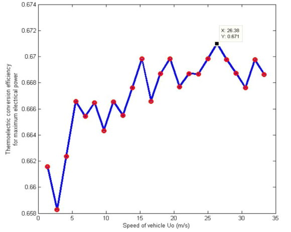
The thermoelectric system is an indispensable part in energy recovery. It can convert waste energy into new power through a thermoelectric engine to improve the commuting efficiency or operation efficiency of vehicles. Analysis and simulation of the thermoelectric generator, as shown in Figure 12. The results show that the efficiency varies between 65.83% and 67.1%. Considering the weak thermoelectric performance of the modules available in the market, this is quite encouraging [22]. The thermoelectric system can also reduce electricity consumption. The waste heat and mechanical energy available on the highway can be converted into electricity, which can enhance the overall efficiency of the engine and improve performance, as shown in Figure 13. Ultimately, the commuting distance can be extended [23].
In the current energy usage pattern, it is necessary to recognize various different forms of energy, including chemical energy, electrical energy, mechanical energy and thermal energy. Utilizing thermoelectric generators (TEGs) to exploit the untapped potential of waste heat, particularly that from hybrid vehicle exhausts. The aim of this project is to conduct an in-depth study on the complexity of this technology, with a particular focus on the efficiency of the teg in converting the waste heat from vehicle exhaust into usable electrical energy. To conduct the module test, thermal and electrical contact resistances need to be taken into account. Since this module is composed of multiple thermocouples, it is necessary to ensure that its size conforms to the design for exhaust as well as the design (shown in Figure 14). By modeling this module, the maximum potential for generating electrical energy through thermoelectricity can be exploited. As the thermoelectric module is a sensitive component, careful modeling can prevent unnecessary damage.
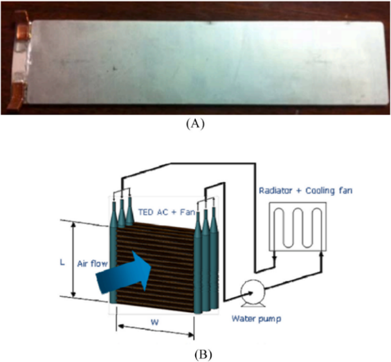
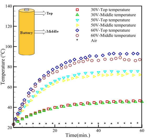
The temperature in the laboratory is maintained within the range of 20 to 25 degrees Celsius, and the environmental pressure is the standard atmospheric pressure. All experiments are based on simulating battery modules and mainly compare and analyze three cooling methods: natural air cooling, pure liquid cooling, and mixed liquid-air cooling. The research focuses on the thermal behavior of the battery under natural air-cooling conditions under different voltage supply conditions. The experimental results show that as the supply voltage increases, the increase in the internal temperature of the battery and its change rate significantly increase. When the heater voltage is raised from 30 volts to 60 volts, the stable temperature achieved by the system almost doubles, and the specific change trend is shown in Figure 15. Subsequently, the researchers evaluated the proposed liquid cooling and mixed thermoelectric liquid-air cooling systems. Under the reference voltage of the heater at 40 volts, the mixed cooling system shows better heat dissipation performance compared to pure liquid cooling, and its effect is also superior to natural air cooling. In addition, to prevent equipment corrosion, a copper shell was added to the system.
This battery system can reduce the corrosion problems caused by coolant. Relevant experiments have been conducted in practical applications. The experiments were carried out in an air environment and also in water.
In aerial conditions, the experimental data revealed that the temperature variation closely mirrored that of the control group without thermal protection. Underwater testing demonstrated that the hybrid thermal management system also experienced a notable decline in temperature. Future studies will prioritize battery packs with more stringent cooling requirements. Additionally, a computational thermal model will be developed and analyzed to facilitate numerical simulations and the refinement of design parameters.
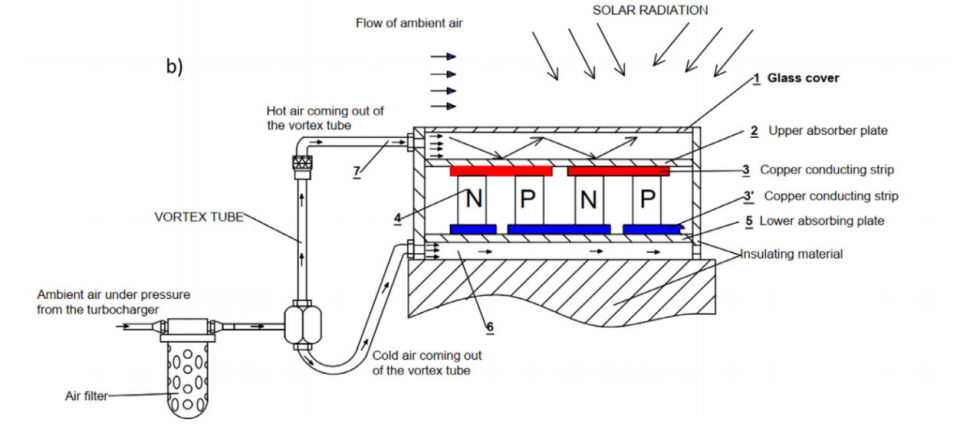
To mitigate global warming, automotive manufacturers must transition to cleaner, more sustainable hybrid vehicles. A key strategy for reducing fuel consumption involves integrating renewable energy solutions, such as a thermoelectric-photovoltaic (TE-PV) hybrid energy system. This system combines two TEGs—a hot-spot engine and a photovoltaic (PV) generator—to dynamically charge hybrid vehicle batteries by harnessing solar radiation and waste heat from a vortex tube. The STEG comprises multiple modules distributed across the vehicle’s sun-exposed surfaces and the vortex tube outlet. At the tube’s exit, hot and cold air streams are separated, with a temperature differential ΔT of ~200°C. These streams are channeled to the hot and cold sides of the STEG, sustaining a high ΔT for efficient energy conversion. The thermoelectric effect, achieved through P-N doped semiconductor pairs, facilitates this heat-to-electricity conversion, as shown in Figure 16. The temperature at the STEG’s hot and cold ends varies with vehicle speed. When stationary, the system reaches peak temperatures, which then decline and stabilize during motion, as shown in
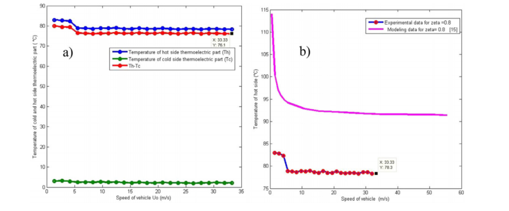
Figure 17. The conversion efficiency depends on the ΔT across the STEG, which is influenced by ambient temperature and solar irradiance, as shown in Figure 18. At 33.33 m/s, recorded values include: the hot side is 76.1°C and the cold side is 2.1°C, the Output is 0.7742 A, 46.85 V, 36.27 W. Validation against mathematical models of analogous systems confirms consistent performance trends. Future research should focus on integrating STEG modules into the vehicle body to minimize aerodynamic drag and prevent additional fuel consumption.
5. Rankine cycle
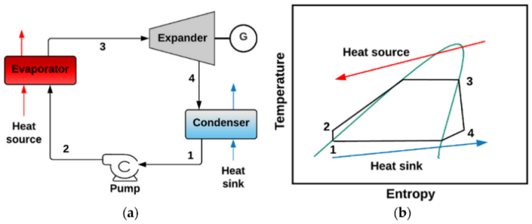
The Rankine cycle is a thermodynamic process, which is generally used in power generation to convert heat into mechanical work. It operates by circulating a working fluid—typically water—through four main components as illustrated in Figure 19 a condenser [26] ,a pump ,an evaporator with an included superheater to add heat and produce steam [27], the steam is used to run the turbine in the expander which powers the generator . This closed-loop system is key to steam power plants, known for efficiently utilizing heat and reducing vehicle emissions. However, challenges remain in size, weight, and performance under variable engine conditions [28].
To recover waste heat and boost engine efficiency, the transcritical CO₂ Rankine cycle (tCO₂RC) replaces water with CO₂ operating above critical pressure [11,29,30] As shown in
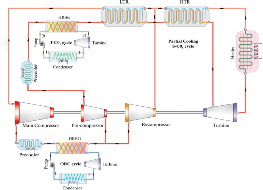
Figure 20, a combined system uses S-CO₂ as the primary cycle and reuses exhaust heat via T-CO₂ and ORC sub-cycles. This integration maximizes both high- and low-temperature heat use, improving overall energy efficiency.

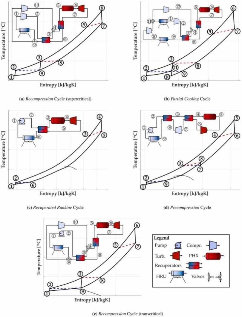
This study evaluates five CO₂-based power cycles—Recompression (supercritical and transcritical), Partial Cooling, Recuperated Rankine, and Precompression—using exergy analysis. illustrates their operations through T–s diagrams, highlighting how key components interact to extract high-temperature heat (575–725 °C) [31]. Table 3 summarizes details optimal design parameters for comparing performance and identifying exergy loss sources.
|
Acronym |
Layout |
Working Fluid |
PRMC |
ERT |
PRPrC |
α |
|
RCCO₂ |
Recompression |
100% CO₂ |
2.37 / 2.45 |
2.20 / 2.27 |
– |
0.29 / 0.29 |
|
PCCO₂ |
Partial Cooling |
100% CO₂ |
2.23 / 2.24 |
3.18 / 3.70 |
1.55 / 1.80 |
0.40 / 0.41 |
|
PrCD1 |
Precompression |
85%CO₂/15% C₆F₆ |
3.22 / 3.22 |
3.91 / 4.20 |
1.31 / 1.41 |
– |
|
RRD2 |
Rec. Rankine |
83%CO₂ /17% TiCl₄ |
2.60 / 2.60 |
2.47 / 2.47 |
– |
– |
|
RCD3 |
Recompression |
80%CO₂ / 20% SO₂ |
3.16 / 3.16 |
2.93 / 2.93 |
– |
0.38 / 0.38 |
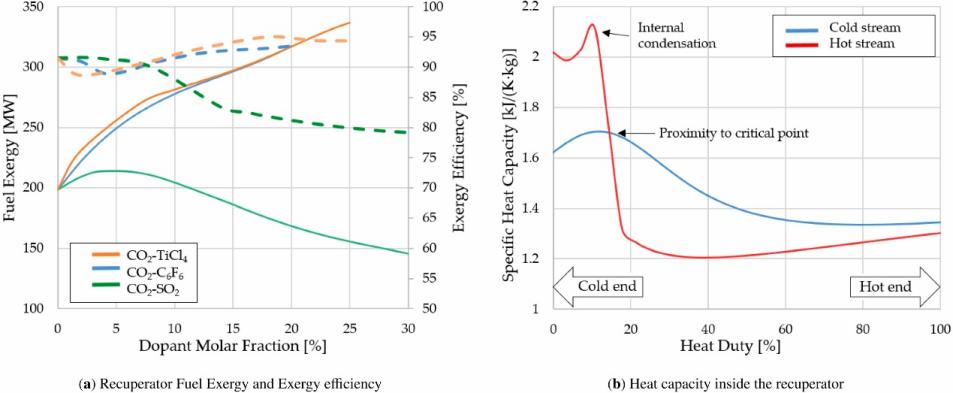
Rodríguez et al. [11] studied how CO₂ mixtures enhance the efficiency of transcritical Rankine cycles for low-grade waste heat recovery. The results in Figure 22 show that pure CO₂ achieves 65–75% exergy efficiency [32],while mixing it with C₆F₆ or TiCl₄ raises efficiency above 90% as dopant concentration increases. In contrast, SO₂ blends reduce efficiency to around 60%. These mixtures also lower exergy losses in typically inefficient components like the evaporator and gas cooler [33,34]. Despite concerns such as flammability, the study confirms the strong potential of CO₂ mixtures for improving cycle performance.
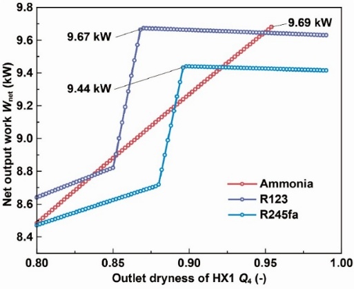
To optimize fluid performance, Wang et al. [35] introduced a heat-matching method that adjusts the dryness point at the evaporator outlet, isolating fluid effects. In a fixed exhaust subcritical Rankine system, pinch-curve analysis. ensures optimal heat exchange. Under constant turbine inlet conditions, ammonia outperforms R123 and R245fa, delivering around 9.69 kW output and about 5.2% higher thermal efficiency due to better heat matching and less exergy loss, as shown in Figure 23.
Figure 24 confirms ammonia’s advantage over R123 and R245fa, supported by Patel et al. [36] , who linked improved thermal matching to efficiency gains. Despite minor pressure drop penalties (<5%), compactness is retained. The study concludes that precise control of evaporation dryness and fluid selection significantly improves Rankine cycle efficiency under fixed boundary conditions.
6. Electric turbochargers
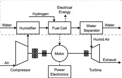
An electric turbocharger is a force induction system that produces extra power by intaking more air during combustion, which combines a normal turbocharger with an electric motor attached to the turbo shaft. Figure 25 shows the structure of the electric turbocharger, where the compressor, turbine, and the motor are connected by the turbo shaft [37]. The compressor draws air in and compresses it and delivers it into the fuel cell. The fuel cell then signals the motor to spin, allowing the turbocharger to intake more air. This will increase the waste energy the turbine can regain and use when humid air is exhausted, which can be used to create more power.
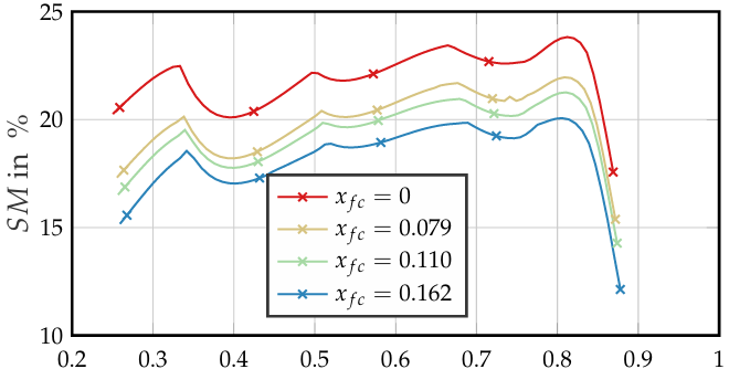
Electric turbochargers improve the maximum power output of the fuel cell system by recollecting and utilizing waste energy from exhaust, but condensation can be a potential problem that affects the efficiency of energy recovery. This study mainly focuses on how condensation impacts the working stability of the turbine and compressor. The areas that will be running Computational Fluid Dynamics (CFD) virtual tests are demonstrated in Figure 26. By running these tests, the turbine performance diagrams in humid air are created. They are later used to construct reduced-order models (ROM) based on Aircraft Engine Simulation for Transient Operation Research (ASTOR) [37] to simulate the different conditions of the vehicle. This include acceleration and deceleration, as well as the steady position where all parameters are likely to remain constant. During this process, the effects of condensation on energy recovery of the electric turbocharger will be projected.

Condensation in the turbine slightly reduces the overall efficiency of the system by 0.1%. In the case where no extra pressure is added, the maximum power output is 77% of the estimated power in the test. By using an electric turbocharger, the power output has improved 7.2% compared with a normal turbocharger. Despite the negligible effect of condensation on efficiency, it still created risks in stability of the system during transient operations. In addition, when the vehicle is decelerating, the surge margin of the compressor decreases up to 12% as shown in Figure 27, where it can lower to 8% [37]. This may cause safety problems in operating the system, leading to lower working efficiency of the electric turbocharger, as the rate of energy recovery may decrease. In the future, improving control systems and developing machines to work with high pressure level of turbine and compressor ratios is necessary to ensure the system’s efficiency and reduce the safety issues.
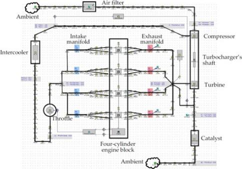
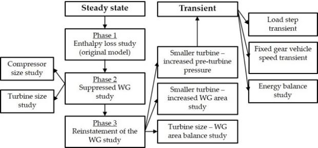
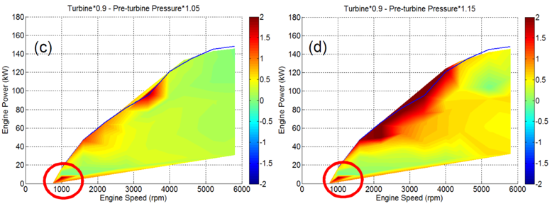
Traditional turbochargers suffer from turbo lag and energy losses, which reduces the overall efficiency of the system. E-turbos are designed to recover energy from exhaust, improve responsiveness in transient operations, and reduce parasitic losses. By using an approved 1D model (GT-Power) of a 2.0L turbocharged SI engine [38] as shown in Figure 28, three steady-state periods in Figure 29 will be focused on. Firstly, the quantity of enthalpy loss will be assessed while relating to the turbine and compressor’s size. Next, studies are made to suppress the wastegate and using electric turbocharger for boost control. Finally, the wastegate will be restored to control pre-turbine pressure and investigate the changes between the size of turbine and area of wastegate. Transient simulations and projections will further estimate and predict changes in efficiency during operations.
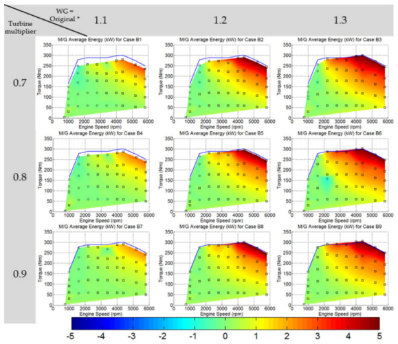
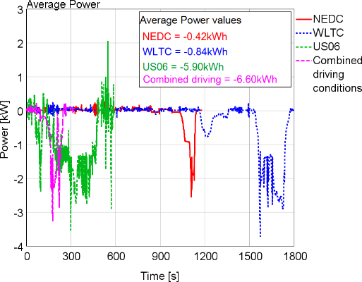
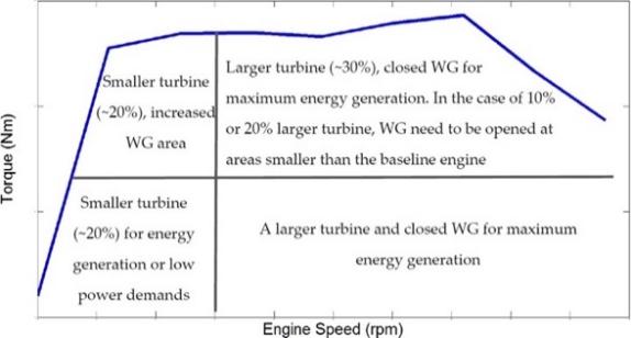
Steady-state analyses reveal that a 10% smaller turbine with 5–15% increased pre-turbine pressure ensures energy harvesting across most operating points as shown in Figure 30. Figure 31 shows the increase in efficiency compared with the baseline engine, although there is existence of peak torque penalty. Driving cycles show net energy regeneration, with combined driving and US06 representing the maximum energy recovered as shown in Figure 32.

Figure 33 balances component sizing to maximize efficiency. In the future, research and development in advanced turbine or compressor matching is in priority
7. Conclusion
This paper systematically compared and evaluated five complementary energy-recovery strategies including regenerative braking control, flywheel buffering, auxiliary thermoelectric generators, Rankine waste heat utilization, and electric turbine compounding to discuss their applicability in extending vehicle range.
• Regenerative braking optimization using pole-changing, validated in MATLAB/Simulink under full torque mode and US06 cycle, achieved ~25% energy savings. Under CTCRDC, regenerative braking contributed 41.09% to energy efficiency and 24.63% to regenerative range.
• Integrating a planetary gear flywheel into a four-wheel-drive buffer improved 0–100 km/h acceleration by 18%, raised interwheel energy return from 0.36 PU to 0.75 PU, cut battery current peaks, and increased powertrain efficiency by 6–8% across J1015, NEDC, and HWFET cycles. This subcritical 20 kr min⁻¹ flywheel serves as the primary power reservoir, extending battery life and range.
• At 33.33 m/s, with a high temperature of 76.1°C and low of 2.1°C, the optimized STEG generated 0.7742 A, 46.85 V, and 36.27 W. The design more fully converts thermal and exhaust energy into electricity, increasing mileage with high efficiency. Integrating the STEG into the vehicle body could eliminate aerodynamic drag penalties, thus avoid extra fuel consumption and enabling practical application without compromising vehicle performance.
• CO₂/R134a blends in transcritical Rankine cycles improved net power output and efficiency by >20%, reducing exergy destruction and condensation issues.
• With a 10% smaller turbine, higher pre-turbine pressure, and motor assistance, the electric turbocharger cut transient response by 70–90%, harvested up to 6.6 kWh per driving cycle, and improved overall efficiency, with only a 5% maximum power penalty and fuel consumption increase of up to 1.8%.
Overall, all methods enhance system efficiency by reclaiming waste energy. The mechanical flywheel ranks highest for its robust, high-power-density storage, rapid response, and independence from battery cycling, making it ideal for urban EVs. Regenerative braking follows for its substantial efficiency gains and range extension with simple integration, though limited by braking opportunities and driving patterns.
References
[1]. B. Ge, D. Sun, W. Wu, and F. Z. Peng, “Winding Design, Modeling, and Control for Pole-Phase Modulation Induction Motors, ” IEEE Trans. Magn., vol. 49, no. 2, pp. 898–911, Feb. 2013, doi: 10.1109/TMAG.2012.2208652.
[2]. E. Libbos, E. Krause, A. Banerjee, and P. T. Krein, “Winding Layout Considerations for Variable-Pole Induction Motors in Electric Vehicles, ” IEEE Trans. Transp. Electrification, vol. 9, no. 4, pp. 5214–5225, Dec. 2023, doi: 10.1109/TTE.2023.3248444.
[3]. I. Karatzaferis, E. C. Tatakis, and N. Papanikolaou, “Investigation of Energy Savings on Industrial Motor Drives Using Bidirectional Converters, ” IEEE Access, vol. 5, pp. 17952–17961, 2017, doi: 10.1109/ACCESS.2017.2748621.
[4]. S. Heydari, P. Fajri, M. Rasheduzzaman, and R. Sabzehgar, “Maximizing Regenerative Braking Energy Recovery of Electric Vehicles Through Dynamic Low-Speed Cutoff Point Detection, ” IEEE Trans. Transp. Electrification, vol. 5, no. 1, pp. 262–270, Mar. 2019, doi: 10.1109/TTE.2019.2894942.
[5]. B. Sun, T. Gu, B. Li, P. Wang, S. Gao, and S. Wei, “Design and application of electromechanical flywheel hybrid device for electric vehicle, ” Energy Rep., vol. 8, pp. 12570–12582, Nov. 2022, doi: 10.1016/j.egyr.2022.09.078.
[6]. N. Farrokhzad Ershad, R. Tafazzoli Mehrjardi, and M. Ehsani, “High-Performance 4WD Electric Powertrain With Flywheel Kinetic Energy Recovery, ” IEEE Trans. Power Electron., vol. 36, no. 1, pp. 772–784, Jan. 2021, doi: 10.1109/TPEL.2020.3004866.
[7]. R.-C. Talawo, B. E. M. Fotso, and M. Fogue, “An experimental study of a solar thermoelectric generator with vortex tube for hybrid vehicle, ” Int. J. Thermofluids, vol. 10, p. 100079, May 2021, doi: 10.1016/j.ijft.2021.100079.
[8]. S.-K. Kim, B.-C. Won, S.-H. Rhi, S.-H. Kim, J.-H. Yoo, and J.-C. Jang, “Thermoelectric Power Generation System for Future Hybrid Vehicles Using Hot Exhaust Gas, ” J. Electron. Mater., vol. 40, no. 5, pp. 778–783, May 2011, doi: 10.1007/s11664-011-1569-1.
[9]. S. Shaharizal, M. R. Ahmad, and H. F. Hawari, “Design and analysis of a hybrid energy harvester for self-powered sensor, ” in TENCON 2017 - 2017 IEEE Region 10 Conference, Nov. 2017, pp. 1016–1021. doi: 10.1109/TENCON.2017.8228006.
[10]. J. C. Jiménez-García, A. Ruiz, A. Pacheco-Reyes, and W. Rivera, “A Comprehensive Review of Organic Rankine Cycles, ” Processes, vol. 11, no. 7, Art. no. 7, July 2023, doi: 10.3390/pr11071982.
[11]. Pablo Rodríguez-deArriba et al., “The potential of transcritical cycles based on CO2 mixtures: An exergy-based analysis, ” Renew. Energy, vol. 199, pp. 1606–1628, Nov. 2022, doi: 10.1016/j.renene.2022.09.041.
[12]. G. Sandrini, D. Chindamo, and M. Gadola, “Regenerative Braking Logic That Maximizes Energy Recovery Ensuring the Vehicle Stability, ” Energies, vol. 15, no. 16, 2022, doi: 10.3390/en15165846.
[13]. B. Güney and H. Kılıç, “Research on Regenerative Braking Systems: A Review, ” Int. J. Sci. Res. IJSR, vol. 9, pp. 160–166, Sept. 2020, doi: 10.21275/SR20902143703.
[14]. R. K. Chidambaram et al., “Effect of Regenerative Braking on Battery Life, ” Energies, vol. 16, no. 14, 2023, doi: 10.3390/en16145303.
[15]. S. Dabral, S. Basak, and C. Chakraborty, “Regenerative Braking Efficiency Enhancement Using Pole-Changing Induction Motor, ” IEEE Trans. Transp. Electrification, vol. 10, no. 3, pp. 7580–7590, Sept. 2024, doi: 10.1109/TTE.2023.3331448.
[16]. J. Kropiwnicki and T. Gawłas, “Energy efficiency of a car driving with regenerative braking, ” Combust. Engines, July 2025, doi: 10.19206/ce-207152.
[17]. A. Boretti, “Advancing sustainable mobility: Integrating flywheel kinetic energy recovery systems with high-efficiency hydrogen internal combustion engines, ” Int. J. Hydrog. Energy, vol. 125, pp. 354–363, May 2025, doi: 10.1016/j.ijhydene.2025.04.094.
[18]. M. E. Amiryar and K. R. Pullen, “A Review of Flywheel Energy Storage System Technologies and Their Applications, ” Appl. Sci., vol. 7, no. 3, 2017, doi: 10.3390/app7030286.
[19]. K. Erhan and E. Özdemir, “Prototype production and comparative analysis of high-speed flywheel energy storage systems during regenerative braking in hybrid and electric vehicles, ” J. Energy Storage, vol. 43, p. 103237, Nov. 2021, doi: 10.1016/j.est.2021.103237.
[20]. R. Takarli et al., “A Comprehensive Review on Flywheel Energy Storage Systems: Survey on Electrical Machines, Power Electronics Converters, and Control Systems, ” IEEE Access, vol. 11, pp. 81224–81255, 2023, doi: 10.1109/ACCESS.2023.3301148.
[21]. S. Rijal, S. K. Labh, Y. Bajgain, D. Bastakoti, and S. Acharya, Recent Advancements in Kinetic Energy Recovery Systems in Automobile. 2023.
[22]. F. Sher et al., “Novel strategies to reduce engine emissions and improve energy efficiency in hybrid vehicles, ” Clean. Eng. Technol., vol. 2, p. 100074, June 2021, doi: 10.1016/j.clet.2021.100074.
[23]. S. Ezzitouni et al., “Electrical Modelling and Mismatch Effects of Thermoelectric Modules on Performance of a Thermoelectric Generator for Energy Recovery in Diesel Exhaust Systems, ” Energies, vol. 14, no. 11, 2021, doi: 10.3390/en14113189.
[24]. M. K. Mahek, M. Ramadan, S. S. bin Dol, M. Ghazal, and M. Alkhedher, “A comprehensive review of thermoelectric cooling technologies for enhanced thermal management in lithium-ion battery systems, ” Heliyon, vol. 10, no. 24, Dec. 2024, doi: 10.1016/j.heliyon.2024.e40649.
[25]. “Electric vehicle battery thermal management system with thermoelectric cooling, ” Energy Rep., vol. 5, pp. 822–827, Nov. 2019, doi: 10.1016/j.egyr.2019.06.016.
[26]. A. Fouda, H. Elattar, S. Rubaiee, A. S. B. Mahfouz, and A. M. Alharbi, “Thermodynamic and Performance Assessment of an Innovative Solar-Assisted Tri-Generation System for Water Desalination, Air-Conditioning, and Power Generation, ” Eng. Technol. Appl. Sci. Res., vol. 12, no. 5, Art. no. 5, Oct. 2022, doi: 10.48084/etasr.5237.
[27]. O. A. Marzouk, “Condenser Pressure Influence on Ideal Steam Rankine Power Vapor Cycle using the Python Extension Package Cantera for Thermodynamics, ” Eng. Technol. Appl. Sci. Res., vol. 14, no. 3, Art. no. 3, June 2024, doi: 10.48084/etasr.7277.
[28]. J. C. Jiménez-García, A. Ruiz, A. Pacheco-Reyes, and W. Rivera, “A Comprehensive Review of Organic Rankine Cycles, ” Processes, vol. 11, no. 7, Art. no. 7, July 2023, doi: 10.3390/pr11071982.
[29]. Peng Liu a b et al., “Experimental study on transcritical Rankine cycle (TRC) using CO2/R134a mixtures with various composition ratios for waste heat recovery from diesel engines, ” Energy Convers. Manag., vol. 208, p. 112574, Mar. 2020, doi: 10.1016/j.enconman.2020.112574.
[30]. “Cascading the Transcritical CO2 and Organic Rankine Cycles with Supercritical CO2 Cycles for Waste Heat Recovery, ” Int. J. Thermofluids, vol. 20, p. 100508, Nov. 2023, doi: 10.1016/j.ijft.2023.100508.
[31]. “Analysis of the thermodynamic performance of transcritical CO2 power cycle configurations for low grade waste heat recovery, ” Energy Rep., vol. 8, pp. 4196–4208, Nov. 2022, doi: 10.1016/j.egyr.2022.03.040.
[32]. “Review of supercritical CO2 power cycle technology and current status of research and development, ” Nucl. Eng. Technol., vol. 47, no. 6, pp. 647–661, Oct. 2015, doi: 10.1016/j.net.2015.06.009.
[33]. “Energy and Exergy Analysis of Transcritical CO2 Cycles for Heat Pump Applications.” Accessed: July 18, 2025. [Online]. Available: https: //www.mdpi.com/2071-1050/16/17/7511
[34]. P. Bouteiller, M.-F. Terrier, and P. Tobaly, “Experimental Study of Heat Pump Thermodynamic Cycles Using CO 2 Based Mixtures -Methodology and First Results, ” 2017, p. 020052. doi: 10.1063/1.4976271.
[35]. “Process design methodology for rankine cycle based on heat matching, ” Renew. Sustain. Energy Rev., vol. 193, p. 114295, Apr. 2024, doi: 10.1016/j.rser.2024.114295.
[36]. “Effects of working fluid on thermal performance and impact force of two-phase closed thermosyphon at low heat flux, ” Int. Commun. Heat Mass Transf., vol. 167, p. 109311, Sept. 2025, doi: 10.1016/j.icheatmasstransfer.2025.109311.
[37]. S. Lück, T. Wittmann, J. Göing, C. Bode, and J. Friedrichs, “Impact of Condensation on the System Performance of a Fuel Cell Turbocharger, ” Machines, vol. 10, p. 59, Jan. 2022, doi: 10.3390/machines10010059.
[38]. P. Dimitriou, R. Burke, Q. Zhang, C. Copeland, and H. Stoffels, “Electric Turbocharging for Energy Regeneration and Increased Efficiency at Real Driving Conditions, ” Appl. Sci., vol. 7, no. 4, Apr. 2017, doi: 10.3390/app7040350.
Cite this article
Pan,J.;Song,C.;Zhang,Y.;Zhu,Z.;Dang,T. (2025). A Review of the Overall Efficiency of Automotive Energy Recovery Systems in Extending Travel Range. Applied and Computational Engineering,188,6-30.
Data availability
The datasets used and/or analyzed during the current study will be available from the authors upon reasonable request.
Disclaimer/Publisher's Note
The statements, opinions and data contained in all publications are solely those of the individual author(s) and contributor(s) and not of EWA Publishing and/or the editor(s). EWA Publishing and/or the editor(s) disclaim responsibility for any injury to people or property resulting from any ideas, methods, instructions or products referred to in the content.
About volume
Volume title: Proceedings of CONF-MCEE 2026 Symposium: Advances in Sustainable Aviation and Aerospace Vehicle Automation
© 2024 by the author(s). Licensee EWA Publishing, Oxford, UK. This article is an open access article distributed under the terms and
conditions of the Creative Commons Attribution (CC BY) license. Authors who
publish this series agree to the following terms:
1. Authors retain copyright and grant the series right of first publication with the work simultaneously licensed under a Creative Commons
Attribution License that allows others to share the work with an acknowledgment of the work's authorship and initial publication in this
series.
2. Authors are able to enter into separate, additional contractual arrangements for the non-exclusive distribution of the series's published
version of the work (e.g., post it to an institutional repository or publish it in a book), with an acknowledgment of its initial
publication in this series.
3. Authors are permitted and encouraged to post their work online (e.g., in institutional repositories or on their website) prior to and
during the submission process, as it can lead to productive exchanges, as well as earlier and greater citation of published work (See
Open access policy for details).
References
[1]. B. Ge, D. Sun, W. Wu, and F. Z. Peng, “Winding Design, Modeling, and Control for Pole-Phase Modulation Induction Motors, ” IEEE Trans. Magn., vol. 49, no. 2, pp. 898–911, Feb. 2013, doi: 10.1109/TMAG.2012.2208652.
[2]. E. Libbos, E. Krause, A. Banerjee, and P. T. Krein, “Winding Layout Considerations for Variable-Pole Induction Motors in Electric Vehicles, ” IEEE Trans. Transp. Electrification, vol. 9, no. 4, pp. 5214–5225, Dec. 2023, doi: 10.1109/TTE.2023.3248444.
[3]. I. Karatzaferis, E. C. Tatakis, and N. Papanikolaou, “Investigation of Energy Savings on Industrial Motor Drives Using Bidirectional Converters, ” IEEE Access, vol. 5, pp. 17952–17961, 2017, doi: 10.1109/ACCESS.2017.2748621.
[4]. S. Heydari, P. Fajri, M. Rasheduzzaman, and R. Sabzehgar, “Maximizing Regenerative Braking Energy Recovery of Electric Vehicles Through Dynamic Low-Speed Cutoff Point Detection, ” IEEE Trans. Transp. Electrification, vol. 5, no. 1, pp. 262–270, Mar. 2019, doi: 10.1109/TTE.2019.2894942.
[5]. B. Sun, T. Gu, B. Li, P. Wang, S. Gao, and S. Wei, “Design and application of electromechanical flywheel hybrid device for electric vehicle, ” Energy Rep., vol. 8, pp. 12570–12582, Nov. 2022, doi: 10.1016/j.egyr.2022.09.078.
[6]. N. Farrokhzad Ershad, R. Tafazzoli Mehrjardi, and M. Ehsani, “High-Performance 4WD Electric Powertrain With Flywheel Kinetic Energy Recovery, ” IEEE Trans. Power Electron., vol. 36, no. 1, pp. 772–784, Jan. 2021, doi: 10.1109/TPEL.2020.3004866.
[7]. R.-C. Talawo, B. E. M. Fotso, and M. Fogue, “An experimental study of a solar thermoelectric generator with vortex tube for hybrid vehicle, ” Int. J. Thermofluids, vol. 10, p. 100079, May 2021, doi: 10.1016/j.ijft.2021.100079.
[8]. S.-K. Kim, B.-C. Won, S.-H. Rhi, S.-H. Kim, J.-H. Yoo, and J.-C. Jang, “Thermoelectric Power Generation System for Future Hybrid Vehicles Using Hot Exhaust Gas, ” J. Electron. Mater., vol. 40, no. 5, pp. 778–783, May 2011, doi: 10.1007/s11664-011-1569-1.
[9]. S. Shaharizal, M. R. Ahmad, and H. F. Hawari, “Design and analysis of a hybrid energy harvester for self-powered sensor, ” in TENCON 2017 - 2017 IEEE Region 10 Conference, Nov. 2017, pp. 1016–1021. doi: 10.1109/TENCON.2017.8228006.
[10]. J. C. Jiménez-García, A. Ruiz, A. Pacheco-Reyes, and W. Rivera, “A Comprehensive Review of Organic Rankine Cycles, ” Processes, vol. 11, no. 7, Art. no. 7, July 2023, doi: 10.3390/pr11071982.
[11]. Pablo Rodríguez-deArriba et al., “The potential of transcritical cycles based on CO2 mixtures: An exergy-based analysis, ” Renew. Energy, vol. 199, pp. 1606–1628, Nov. 2022, doi: 10.1016/j.renene.2022.09.041.
[12]. G. Sandrini, D. Chindamo, and M. Gadola, “Regenerative Braking Logic That Maximizes Energy Recovery Ensuring the Vehicle Stability, ” Energies, vol. 15, no. 16, 2022, doi: 10.3390/en15165846.
[13]. B. Güney and H. Kılıç, “Research on Regenerative Braking Systems: A Review, ” Int. J. Sci. Res. IJSR, vol. 9, pp. 160–166, Sept. 2020, doi: 10.21275/SR20902143703.
[14]. R. K. Chidambaram et al., “Effect of Regenerative Braking on Battery Life, ” Energies, vol. 16, no. 14, 2023, doi: 10.3390/en16145303.
[15]. S. Dabral, S. Basak, and C. Chakraborty, “Regenerative Braking Efficiency Enhancement Using Pole-Changing Induction Motor, ” IEEE Trans. Transp. Electrification, vol. 10, no. 3, pp. 7580–7590, Sept. 2024, doi: 10.1109/TTE.2023.3331448.
[16]. J. Kropiwnicki and T. Gawłas, “Energy efficiency of a car driving with regenerative braking, ” Combust. Engines, July 2025, doi: 10.19206/ce-207152.
[17]. A. Boretti, “Advancing sustainable mobility: Integrating flywheel kinetic energy recovery systems with high-efficiency hydrogen internal combustion engines, ” Int. J. Hydrog. Energy, vol. 125, pp. 354–363, May 2025, doi: 10.1016/j.ijhydene.2025.04.094.
[18]. M. E. Amiryar and K. R. Pullen, “A Review of Flywheel Energy Storage System Technologies and Their Applications, ” Appl. Sci., vol. 7, no. 3, 2017, doi: 10.3390/app7030286.
[19]. K. Erhan and E. Özdemir, “Prototype production and comparative analysis of high-speed flywheel energy storage systems during regenerative braking in hybrid and electric vehicles, ” J. Energy Storage, vol. 43, p. 103237, Nov. 2021, doi: 10.1016/j.est.2021.103237.
[20]. R. Takarli et al., “A Comprehensive Review on Flywheel Energy Storage Systems: Survey on Electrical Machines, Power Electronics Converters, and Control Systems, ” IEEE Access, vol. 11, pp. 81224–81255, 2023, doi: 10.1109/ACCESS.2023.3301148.
[21]. S. Rijal, S. K. Labh, Y. Bajgain, D. Bastakoti, and S. Acharya, Recent Advancements in Kinetic Energy Recovery Systems in Automobile. 2023.
[22]. F. Sher et al., “Novel strategies to reduce engine emissions and improve energy efficiency in hybrid vehicles, ” Clean. Eng. Technol., vol. 2, p. 100074, June 2021, doi: 10.1016/j.clet.2021.100074.
[23]. S. Ezzitouni et al., “Electrical Modelling and Mismatch Effects of Thermoelectric Modules on Performance of a Thermoelectric Generator for Energy Recovery in Diesel Exhaust Systems, ” Energies, vol. 14, no. 11, 2021, doi: 10.3390/en14113189.
[24]. M. K. Mahek, M. Ramadan, S. S. bin Dol, M. Ghazal, and M. Alkhedher, “A comprehensive review of thermoelectric cooling technologies for enhanced thermal management in lithium-ion battery systems, ” Heliyon, vol. 10, no. 24, Dec. 2024, doi: 10.1016/j.heliyon.2024.e40649.
[25]. “Electric vehicle battery thermal management system with thermoelectric cooling, ” Energy Rep., vol. 5, pp. 822–827, Nov. 2019, doi: 10.1016/j.egyr.2019.06.016.
[26]. A. Fouda, H. Elattar, S. Rubaiee, A. S. B. Mahfouz, and A. M. Alharbi, “Thermodynamic and Performance Assessment of an Innovative Solar-Assisted Tri-Generation System for Water Desalination, Air-Conditioning, and Power Generation, ” Eng. Technol. Appl. Sci. Res., vol. 12, no. 5, Art. no. 5, Oct. 2022, doi: 10.48084/etasr.5237.
[27]. O. A. Marzouk, “Condenser Pressure Influence on Ideal Steam Rankine Power Vapor Cycle using the Python Extension Package Cantera for Thermodynamics, ” Eng. Technol. Appl. Sci. Res., vol. 14, no. 3, Art. no. 3, June 2024, doi: 10.48084/etasr.7277.
[28]. J. C. Jiménez-García, A. Ruiz, A. Pacheco-Reyes, and W. Rivera, “A Comprehensive Review of Organic Rankine Cycles, ” Processes, vol. 11, no. 7, Art. no. 7, July 2023, doi: 10.3390/pr11071982.
[29]. Peng Liu a b et al., “Experimental study on transcritical Rankine cycle (TRC) using CO2/R134a mixtures with various composition ratios for waste heat recovery from diesel engines, ” Energy Convers. Manag., vol. 208, p. 112574, Mar. 2020, doi: 10.1016/j.enconman.2020.112574.
[30]. “Cascading the Transcritical CO2 and Organic Rankine Cycles with Supercritical CO2 Cycles for Waste Heat Recovery, ” Int. J. Thermofluids, vol. 20, p. 100508, Nov. 2023, doi: 10.1016/j.ijft.2023.100508.
[31]. “Analysis of the thermodynamic performance of transcritical CO2 power cycle configurations for low grade waste heat recovery, ” Energy Rep., vol. 8, pp. 4196–4208, Nov. 2022, doi: 10.1016/j.egyr.2022.03.040.
[32]. “Review of supercritical CO2 power cycle technology and current status of research and development, ” Nucl. Eng. Technol., vol. 47, no. 6, pp. 647–661, Oct. 2015, doi: 10.1016/j.net.2015.06.009.
[33]. “Energy and Exergy Analysis of Transcritical CO2 Cycles for Heat Pump Applications.” Accessed: July 18, 2025. [Online]. Available: https: //www.mdpi.com/2071-1050/16/17/7511
[34]. P. Bouteiller, M.-F. Terrier, and P. Tobaly, “Experimental Study of Heat Pump Thermodynamic Cycles Using CO 2 Based Mixtures -Methodology and First Results, ” 2017, p. 020052. doi: 10.1063/1.4976271.
[35]. “Process design methodology for rankine cycle based on heat matching, ” Renew. Sustain. Energy Rev., vol. 193, p. 114295, Apr. 2024, doi: 10.1016/j.rser.2024.114295.
[36]. “Effects of working fluid on thermal performance and impact force of two-phase closed thermosyphon at low heat flux, ” Int. Commun. Heat Mass Transf., vol. 167, p. 109311, Sept. 2025, doi: 10.1016/j.icheatmasstransfer.2025.109311.
[37]. S. Lück, T. Wittmann, J. Göing, C. Bode, and J. Friedrichs, “Impact of Condensation on the System Performance of a Fuel Cell Turbocharger, ” Machines, vol. 10, p. 59, Jan. 2022, doi: 10.3390/machines10010059.
[38]. P. Dimitriou, R. Burke, Q. Zhang, C. Copeland, and H. Stoffels, “Electric Turbocharging for Energy Regeneration and Increased Efficiency at Real Driving Conditions, ” Appl. Sci., vol. 7, no. 4, Apr. 2017, doi: 10.3390/app7040350.