


1. Introduction
Energy recovery systems can save energy by recovering the energy usually lost in traditional cars in the form of electricity and store the recovered energy to be used in the future. We assessed the feasibility of implementation of automobile devices used to compare under multiple environments and conditions to determine whether the driving efficiency will be improved.
Previous research underscored the significant potential of TEGs in recovering power [1,2]. The feasibility of TEGs for charging automobile batteries and obtaining quantifiable power outputs by careful positioning of the modules and effective thermal management are well established [1,2].
E-Turbos are gaining great attention in automotive engineering because of their potential to reduce turbo hysteresis and enhance energy regeneration. Turbo lag reduces the reliability of E-Turbos, thus rendering the generator system unable to capture energy from exhaust gas. Current research show that E-Turbos improve transient response by reducing turbo lag, enhancing engine performance under varying loads. Simulink systems show that E-turbos can reduce the brake specific fuel consumption and improve response performance during acceleration [3]. Simulation models demonstrate that the efficiency of E-Turbos is highly dependent on optimized control strategies rather than solely on turbine size [4].
FESSs stores energy as rotational kinetic energy, which is more efficient and increases power output. The feasibility of using FESSs in high-power application scenarios have been successfully tested. Based on the analysis of rotor mass, bearing type, and power output involved in flywheel design by automotive companies and universities, planetary gear sets and continuously variable transmissions are combined to form a new flywheel power system. It has solved the shortcomings of high cost and heavy structure of traditional flywheel power systems. It not only adds selling points for car manufacturers, but especially for users, they no longer need to worry about vehicle energy consumption, greatly reducing the cost of using the vehicle, achieving two goals at once. In addition, there are already successful application cases of this power system in public buses and the power systems of GT3 racing cars.
Currently, RBSs are some of the most promising energy regenerative systems in development. RBSs recover the energy usually lost during the braking and deceleration process through electric motors connected to the wheels. The electric power recovered can then be used on all sorts of subsystems. Past papers have shown that it is possible to install RBSs on hybrid electric vehicles (HEVs) and electric vehicles (EVs), among others.
ORC-based systems are very effective at recovering energy, with many research into how to squeeze every bit of performance from it.
2. Thermoelectric generators
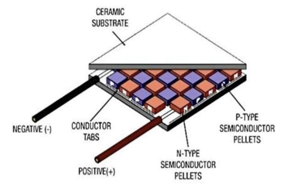
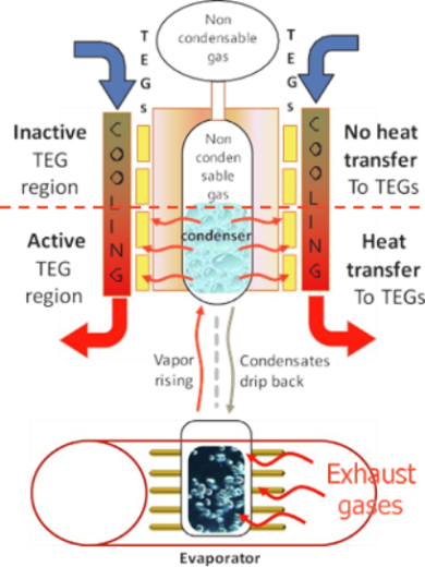
TEGs are devices that convert heat energy to electricity according to the Seebeck effect. As shown in Figure 1, TEGs consist of n-type and p-type semiconductors that are electrically connected in series [2]. This application enables the recovery of waste heat, such as the heat from the exhaust system of an automobile. As shown in Figure 2, the Variable Conductance Thermosiphon (VCTS) constitutes a closed chamber/pipe containing an evaporator at the bottom. The evaporator is connected to a condenser where the TEG modules are mounted. The efficiency of these units depends on the temperature range of the automobile. TEGs are attractive modules for automotive vehicle because they do not need moving parts, cutting down maintenance costs [5].
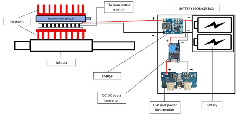
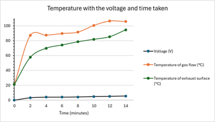
As shown in Figure 3, heat is directed through exhaust system, facilitating thermal energy transfer to a thermoelectric module through the heatsink. A thermal paste filler enhances overall efficiency. In addition, a radiator cooling block is engaged to accommodate elevated exhaust temperatures. This process generates a voltage, which is subsequently directed to a TP4056 charging module. The TP4056 is linked to a battery and a DC-DC boost commutator, and ultimately connected to a USB port power bank module. As shown in Table 1, it included placing TEG at varying distance from heat source (such as vehicle exhaust), measured voltage of each TEG by multimeter. As shown in Figure 4 using infrared thermometer and multimeter measured the exhaust temperature with the value of voltage and time taken [1].
Experiments indicate a voltage decrease when the distance to the heat source is increased as shown in Table 1. This indicates that thermal proximity is an important parameter when implementing. Thus, understanding how the position of a TEG affects voltage production provides useful guidance for designing more efficient energy collecting systems. As shown in Figure 4, about 4 V was produced in 2 minutes of heating. When the temperature of the gas flow and exhaust surface increased to the maximum point at 14 minutes, it increased to 5.5V. These indicate TEGs can quickly generate power [1].
|
Distance (cm) |
80 |
84 |
88 |
92 |
96 |
96 |
|
Voltage (V) |
1.34 |
1.21 |
1.15 |
1.06 |
1.03 |
0.98 |
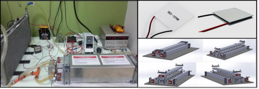
As shown in Figure 5, this experiment uses TEC1-12706 TEGs connect to exhaust pipe and incorporate the radiator to make a temperature difference between the hot and cold junctions. The hot junctions are attached to the heat source and the cold junctions are placed on a heat sink [2].
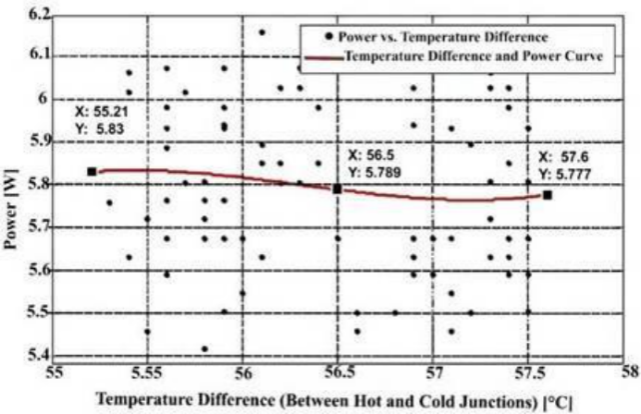
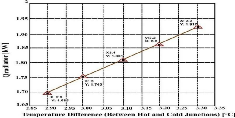
When the temperature difference between the hot and cold junctions around average 56.5°C, the Peltier modules, which has the same principle as thermoelectric module, generated between 5.77 W and 5.83 W, produced an average of 5.8 W electrical energy are shown in Figure 6. It illustrated that a modest change in temperature can generate steady power. As shown in Figure 7, the cooling load was calculated to 1.792 KW, which will impose an extra requirement on the engine if Peltier system attached to vehicle. So a reduced cooling load or increased electrical power output could resolve this inefficiency [2].
3. Electric turbochargers
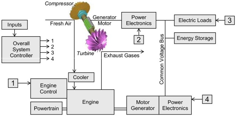
An E-Turbo is a compact mechanical device that combines the parts of a traditional turbocharger with an integrated electric motor. The feasibility implementing E-Turbos depends on the compatibility and complexity of the existing system and technology readiness. An E-Turbo is placed near the compressor to fit current engines as shown in Figure 8. It significantly reduces turbo lag, instant spool-up of the compressor is achieved by utilizing an electric motor. This improving throttle response especially at low engine speeds and thus improving fuel efficiency. The challenges needed to overcome is the control, power and cooling system of the engine. Some E-turbos have entered early production. However, more work is needed to reduce costs and simplify system integration before it can be widely used [6].
Nowadays, engines benefit from traditional turbochargers, but they lack fast transient response at low engine speeds despite efficiency improvements. E-Turbos can improve this, while increasing energy recovery efficiency at the same time.
GT-Power was developed as a simulation model to evaluate the feasibility of energy recovery in the electric turbocharger system under real driving conditions. It included a 2.0L turbocharger gasoline engine, a M/G unit mounted on the turbocharger shaft, dual PID controllers for pressure regulation, and real-time computation of thermal and power flows throughout the cycle. They were tested under NEDC and WLTC. They performed dynamic simulations of thermal and power flows under different driving cycles to obtain energy recovery power and heat distribution data. As shown in Table 2, it’s used to constrain the key operating states of the engine model, especially the turbine temperature, pressure and torque [7].
|
Parameters |
Units |
Values |
|
Torque of engine |
(Nm) |
304 |
|
Temperature of turbine |
(◦C) |
1000 |
|
Speed of turbocharger |
(krpm) |
200 |
|
Pressure of pre-turbine |
(bar) |
3 |
|
Temperature of post-compressor |
(◦C) |
200 |
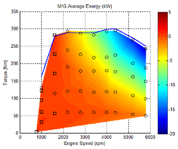
As Figure 9 shows, the system recovered 112Wh of electrical energy under WLTC, which represents 18.1% of the 617Wh of available exhaust energy. Under NEDC, 54Wh was recovered from 398Wh, yielding a 13.6% efficiency. They demonstrate that the E-Turbo effectively converted a significant portion of exhaust heat into electricity without thermal overload, particularly under transient, high-load driving conditions. This increases the feasibility of implementing E-Turbo technology in real-world applications, especially as part of hybrid powertrains aimed at improving overall system efficiency [7].
Traditional internal combustion cars face pressure from environmental regulations. The combination of a combustion engine and a E-Turbo system is considered as an intermediate transition solution, but it still faces some difficulties, such as poor power response and turbo lag of traditional turbocharger. This paper discusses whether the combination of E-Turbo, H2ICE, and hybrid system can work efficiently to provide a feasible solution.
This study selected a verified turbocharged engine computational model to understand the engine’s transient response, steady-state operation under extreme conditions. The hardware parameters of the simulator are shown in Table 3. After that, the simulation data of the E-Turbo hydrogen internal combustion engine with that of a traditional turbocharged engine was compared [8].
Data shows that the system achieves a brake mean effective pressure of more than 30 bar and a braking efficiency of 45%, which is significantly better than a traditional turbocharged engine. Through electric compensation and energy recovery, E-Turbos effectively overcome the problems of insufficient boost and delayed response of traditional turbines under lean combustion conditions. The findings indicate that electric turbocharger technology effectively enhances both the power density and the thermal efficiency of hydrogen-fueled internal combustion engine [8].
|
Parameter |
Value |
|
Bore [mm] |
60 |
|
Stroke [mm] |
60 |
|
Connecting rod length [mm] |
135 |
|
Piston pin offset [mm] |
0 |
|
Displacement/Cylinder [L] |
0.17 |
|
Total displacement [L] |
0.679 |
|
Number of cylinders |
4 |
|
Compression ratio |
17 |
|
Bore/Stroke |
1 |
|
IVC [CA] |
− 164 |
|
EVO [CA] |
174 |
|
IVO [CA] |
349 |
|
EVC [CA] |
374 |
4. Flywheel energy storage systems methods
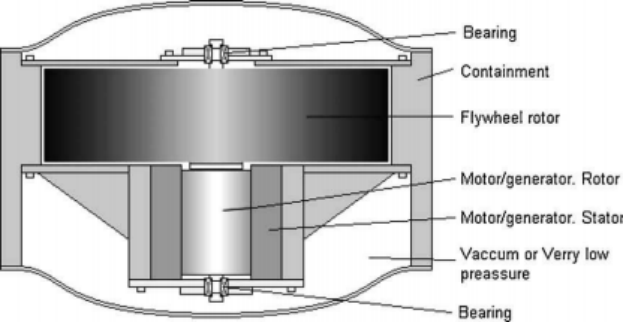
FESSs stores and release electrical power using kinetic energy possessed by a rotating body during rotation. The structure is shown in Figure 10 [9]. The flywheel stores excess energy through its moment of inertia, converting kinetic energy into rotational energy to stabilize the engine’s power output.
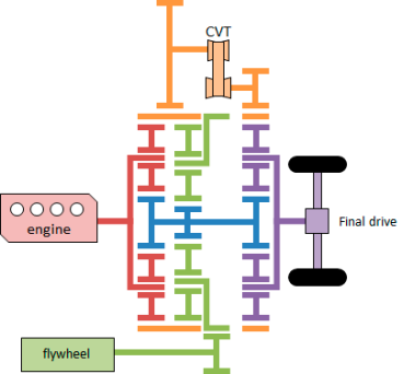
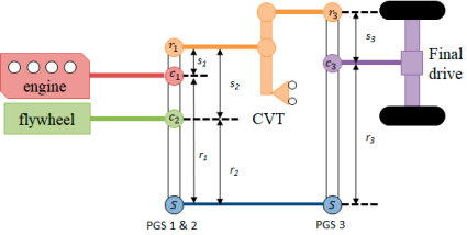
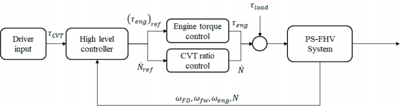
Flywheel electric systems (FESs) are less costly than traditional hybrid electric systems [10]. PS-FHS have the potential to take this a step further by improving fuel economy and driving efficiency through increasing the power output [11]. The research purpose of this paper is to further enhance the performance and verify the feasibility of the power system power-split flywheel hybrid power system (PS-FHS) as shown in Figure 11. To verify whether a PS-FHS can operate normally, the lever model was adopted to analyze the power flow path and operation mode and a matrix equation established to verify the feasibility of using the system. Figure 12 shows the lever model, which expresses the working principle of the power transmission system [12]. Through theoretical calculations, the matrix equation and dynamic modeling were established, and the theoretical feasibility of the dynamical system was further calculated. Figure 13 shows the diagram of the control module. Car driving simulation was added, car parameters were set, control variables such as the impact on acceleration performance and fuel efficiency were set under the assumptions of no tire dynamics, high efficiency and no State of Charge (SOC), and the acceleration time from 0 to 100 kilometers per hour was analyzed on this basis.
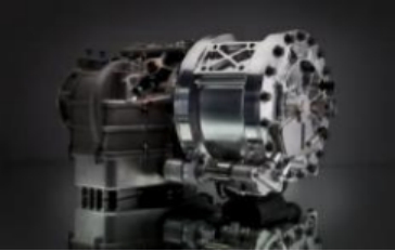
When flywheels are applied in the automotive field, the balanced demand for high power output and high energy output of automobiles needs to be taken into consideration. Applying FESSs in real-world scenarios require both balancing energy and power and designing new types of bearings and extensive testing. To verify the feasibility of the system, this paper installed it on London buses, with each vehicle having a loading capacity of 0.4kWh, which can save approximately 20% to 25% of diesel consumption. Two sets of 60kW flywheel systems were installed on the container crane. Under the conditions of a 1e-minute unloading cycle and a standard container weight of 15 tons, the bidirectional efficiency of this system reached 46%. In terms of vehicles, car manufacturers have installed mechanical flywheel systems on them such as one shown in Figure 14, which has also improved fuel efficiency. The deep discharge rate of EV batteries is assumed to be 3.5%, and the batteries can withstand 1 million cycles of use, far exceeding the lifespan of automobiles.
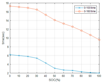
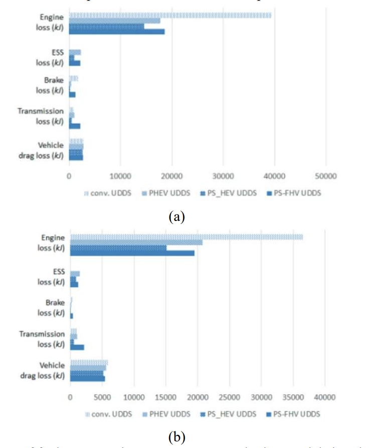
We will then simulate the time to accelerate from 0 to 100km/h and from 0 to 160km/h at 100% SOC. It only takes 2 seconds to accelerate from 0 to 100km/h, while it takes about 9.7 seconds to accelerate from 0 to 160km/h. At 0% SOC, it takes 6 seconds to accelerate from 0 to 100 kilometers per hour, and nearly 10 seconds to accelerate to 160 kilometers per hour, which is significantly higher than the situation with SOC, as shown in Figure 15. In terms of fuel economy, this paper conducted simulated driving scenarios under Urban Dynamometer Driving (UDDS) and Highway Fuel Economy Test (HWFET) driving cycles, and compared and evaluated the performance with that of traditional vehicles, PHEV, power-Split HEVs and others. The results are shown in (b)
Figure 16. The fuel economy of HWFET in high-speed cycles is 19.8 kilometers per liter. The urban cycle of UDDS is 15.1 kilometers per liter. Thus, it can be said that the higher the SOC value, the better the vehicle's acceleration performance. Under 100% SOC conditions, the acceleration performance was enhanced by 42%. From the economy of fuel chart that the fuel economy of PS-FHV lies between that of the other two models. Although it is not outstanding in terms of fuel economy and still has room for improvement, it has excellent acceleration performance.
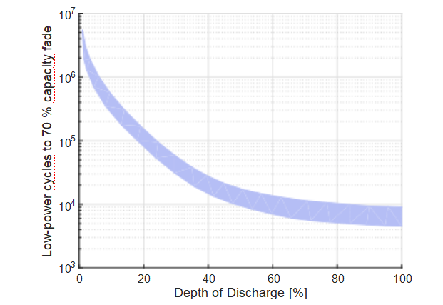
From the above experiments, the FESS has effectively improved the economy of fuel of automobiles and increase output efficiency, and has reliable feasibility. Multiple companies and universities have developed a flywheel system designed for heavy vehicles and combined it with a continuously variable transmission [15], which indirectly demonstrates the wide adaptability of flywheels to various vehicle power systems. Flywheels also have advantages over batteries in terms of service life and power buffering. Figure 17 shows the impact of deep discharge on battery life. The depth of discharge and cycle life decreased exponentially. When the depth of discharge increases from 0% to 100%, the cycle life drops from nearly 10 to the power of 7 to 10 to the power of 3. Table 4 shows a comparison of the implementation of three schemes for vehicle power buffer systems. From this, it can be concluded that the flywheel is lightweight and has the highest specific power, reaching about seven times that of the Electric Double-layer Capacitor (EDLC) system. To summarize, the FESS has an overwhelming advantage in high-power application scenarios, it is bound to become the mainstream power mode in the future.
|
Parameter |
GKN flywheel |
EDLC system |
Lithium battery |
|
Cycle life |
> 106 |
~ 106 |
~ 103 |
|
System weight(kg) |
55 |
370 |
240 |
|
Specific power(kW/kg) |
2200 |
320 |
240 |
5. Regenerative braking systems
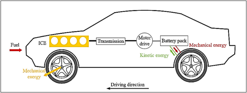
RBSs collect energy that dissipates during the braking process and stores them in the form of electric power [16,17]. They reduce emissions, improve fuel economy and provide better performance while reducing wear on brakes and the engine. As shown in Figure 18, a HEV refitted with a RBS adds a motor controller and an energy management system which works with the motors, gearbox and battery [16] to recover energy during braking. The efficiency of an EV with an RBS was tested in 4 near real-life traffic scenarios. The results are shown in Table 5. The routes are shown in Figure 19.
|
Route Number |
Route Length (m) |
Average Speed (km/h) |
SEC kWh/ (t·100km) |
RBSE kWh/ (t·100km) |
Min Height (m) |
Max Height (m) |
Height Diff. (m) |
|
1 |
2762 |
16 |
10.7 |
5.3 |
41 |
88 |
20 |
|
2 |
2931 |
26 |
8.5 |
4.5 |
40 |
67 |
0 |
|
3 |
3117 |
35 |
6.6 |
1.9 |
45 |
57 |
-2 |
|
4 |
2891 |
45 |
6.2 |
3.6 |
33 |
59 |
-21 |

Top left is route 1. Top right is route 2. Bottom left is route 3. Bottom right is route 4 [19].
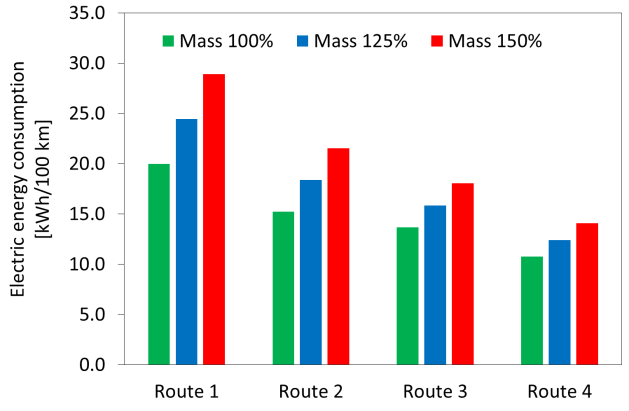
The results showed that high electric energy consumption (EEC) was most probably due to the difference in height during the route, exemplified by route 4 with a finish 21 m lower than the start as shown in Figure 20. On flat roads the average driving speed played the most major part with low EEC being correlated with low average driving speeds as evident in Figure 21.
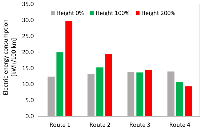
Thus, it can be said that routes with slow traffic and road height differences, even with low net differences, should be avoided to achieve maximum efficiency from an RBS.
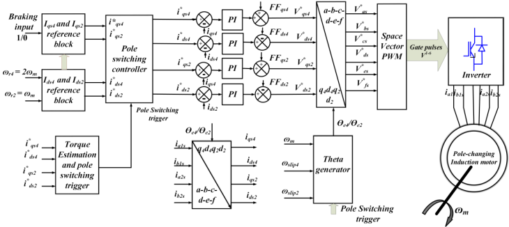
Currently, the most popular motor used in EVs are permanent magnet synchronous motors (PRSMs) for being compact and efficient. However, alternatives are being sought out due to resource limitations and new research. Pole-changing induction motors (PCIMs) are a possible alternative, with the pole-phase modulation technique being one of the frontrunners [20]. An example PCIM shown in Figure 22. Table 6 shows respectively the parameters under which 4-pole mode and 2-pole mode were configured.
|
Symbol |
Meaning |
4-pole configuration values |
2-pole configuration values |
|
Maximum rated current |
9.2 A |
9.2A |
|
|
Stator winding inductance |
0.27 H |
0.522 H |
|
|
Rotor winding inductance |
0.27 H |
0.522 H |
|
|
Magnetizing inductance |
0.258 H |
0.511 H |
|
|
Stator resistance per phase |
|||
|
Rotor resistance per phase |
|||
|
Leakage factor |
0.087 |
0.087 |
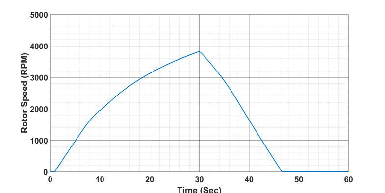
Computer simulations showed promising potential for improving vehicle range by improving regenerative braking efficiency for steady-state performances in different pole configurations. The lower leakage factor of the 2-pole mode resulted in a higher constant power region compared to that of 4-pole mode. 2-pole mode recovered 22%, 4-pole mode recovered 20% and pole-changing mode recovered 27.5% of energy in energy regeneration mode. Figure 23 shows motor speed variation with time, taking the pole-changing drive’s torque profile into account. Thus, it can be said that using PCIMs can have better energy savings.
6. Rankine cycle generators
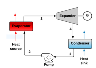
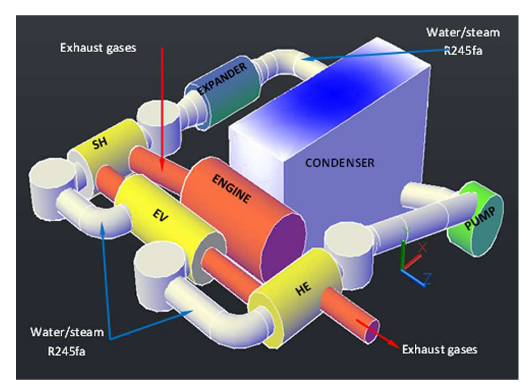
Rankine cycle generators convert waste heat to usable energy without complex burning procedures but using efficient heat-conducting liquids. A Rankine cycle system includes an evaporator, an expander, a condenser, and a pump as shown in Figure 24. The entire process is simplified because it does not account for losses during the transformation process. In the real world the system is extremely sensitive to extreme temperatures, but the temperature resistance of the material and the ability to cool water are constrained by the system. Although increasing the boiler pressure and temperature can improve efficiency, it may exceed the physical limits of the material. Furthermore, high-pressure and high-temperature steam will corrode and embrittle most alloys, increasing the risk of component failure. Despite this, the Rankine cycle is still considered to be a good option to implement in automotive vehicles.
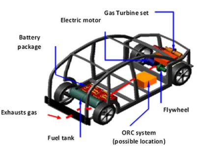
With the worse situation of global environment, it is necessary for humans to find out solution to slow down global warming. And that is what this article will be studying about. To start with, In [21], the article stresses that the combustion engine (1400cc diesel engine) will have at least 35% of energy lost which is “exhaust heat”. It also shows the shortage of traditional steam cycle’s efficiency is “insufficient,” need to use organic material (such as R245fa) to improve the adjustment of the ORC system. To study this, the author uses its patent (ID RM2011A000671), which was designed for test the ORC system and use in a platform called “LETHE” (shown in Figure 25). To get the data, the author uses CAMEL-Pro platform, stimulating the ORC system under different conditions. Furthermore, the author made a comparing experiment to verify that r245fa can replace water in the system. Also, a new heat recover system must to be design, the author uses the formula:
|
A. Steam bottoming plant: |
|
Diesel ICE; |
|
B. Steam bottoming plant: |
|
Diesel ICE; |
|
C. ORC plant, R245fa: |
|
Diesel ICE; |
|
D. ORC plant, R245fa: |
|
Diesel ICE; |
|
E. Steam bottoming plant: |
|
GT set; |
|
F. Steam bottoming plant: |
|
GT set; |
|
G. ORC plant, R245fa: |
|
GT set; |
|
H. ORC plant, R245fa: |
|
GT set; |
|
Case |
1-E |
1-F |
2-G |
2-H |
|
m water/R245fa |
0.008 |
0.012 |
0.075 |
0.12 |
|
Power Output |
1.455 |
2.425 |
1.445 |
2.425 |
|
ORC efficiency |
6.8 |
6.8 |
7.9 |
7.9 |
From Table 8 its clear that, with the new material, the ORC system’s efficiency was around 10%-20%, which is better than the steam cycle (shown in Table 8). Also, the integrated ORC system reduces fuel use by 10-15% (recover 60kw heat). By using CAMEL-Pro stimulate. The system output for electrical power at around 2.5kW, which accounts for 7.9% of the overall efficiency under a 110kW diesel engine. Compared to 1.5kW and 6.8% efficiency for steam cycle in the same configuration. Also, the exhaust temperature across the eight cases reduces the temperature at least 110K heat energy, which indicates that the system has already absorbed heat from wasted heat. The mass-to-flow rate of the fluid used was positively correlated with the net power target: for the 2.5 kW R245fa cases, flow rates had a low of 0.10 kg/s and a high of 0.12 kg/s, while the 1.5 kW one had a low of 0.075 kg/s and a high of 0.09 kg/s. The R245fa cycle significantly outperformed the steam cycle in both efficiency and compactness of heat-exchanger size, with the total thermal exchange surface area for evaporator and superheater sections remaining below 0.04 m² per component. The comparison between water and R245fa was shown in Table 9, which directly shows that even though R245fa need a bigger pump to transport the liquid [21], it has a better performance in everywhere expect pump size require. The reason why R245fa could have such a good performance is origin from its “dry” saturation behavior, which means when the fluid comes to the exit of turbo, it will remain overheat and effectively prevent the damage cause by wet steam [22].So this also why it can improve the efficiency of 1.1%. The final edition of ORC system in car could reach the efficiency nearly 8%, which considered for the reason that it must minimize its size so it can put in a car’s engine box (1.03m*0.83m*0.40m), the figure was shown in 3D (Figure 26). However, the experiment was lacking for road test, the model did not consider of actual driving condition, the environment issue and lots of realistic factors. Overall, the passage has successfully verified the feasibility of small ORC system use in car and could recover for approximately 8% in total energy, and could satisfied half of the assist load requirement, but the system still needs actual experiment to test if the system can work under usual conditions.
|
Fluid |
MW (kg/mol) |
Tcrit (K) |
Pcrit (Pa) |
BP(K) |
|
Water |
0.018 |
646 |
220* |
373 |
|
R245fa |
0.134 |
427 |
36* |
288 |
This paper discusses using the ORC system as an auxiliary power or energy recovery system for vehicles. It also discussed the dynamic working condition adaptability and weight compensation the system faced. Based on the experimental data of the prototype, the researchers established an experimentally validated energy-based powertrain simulation model and carried out the first and second law analysis based on the model to evaluate the potential of engine waste heat recovery. The analysis covers multiple driving cycles and assumes that the vehicle is a continuously charged hybrid vehicle. The research team also developed an ORC quasi-static thermodynamic model, which was calibrated against data in the literature and optimized for the prototype system. In addition, through simulation tests, the researchers evaluated the energy recovery performance under various operating conditions [21].
The study uses Ohio State University’s EcoCAR plug-in HEV as the platform and adopts a multi-scale validation model:
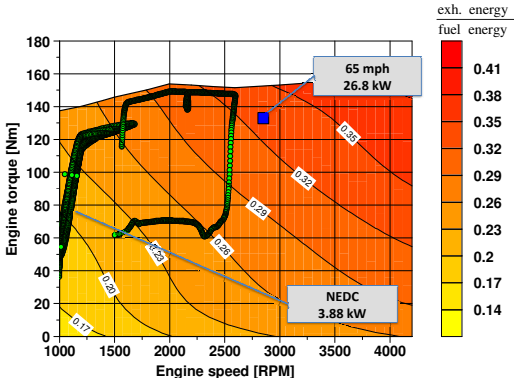
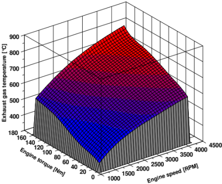
1) Foundation of energy flow analysis: Construct a mapping of exhaust temperature and mass flow based on engine bench test data (Figure 27) and modify the exhaust energy distribution by combining with the catalyst thermal model.
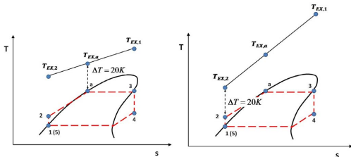
2) Breakthrough in exergy analysis: Quantify the available energy of exhaust gas through the formula e = h − h₀ − T₀⋅ (s − s₀) (Figure 28) and reveal the upper limit of recoverable energy.
3) Optimization of the ORC system: Design a quasi-static model for the R-245fa working fluid, adopt the Pinch-Point method, and dynamically optimize the evaporation pressure (Figure 29).
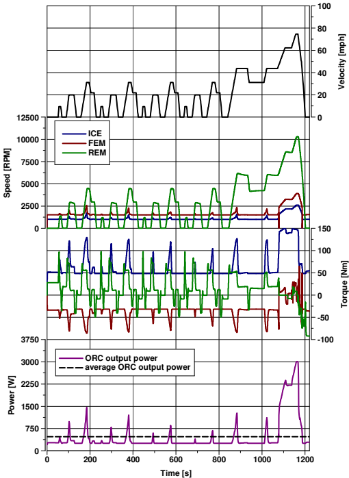
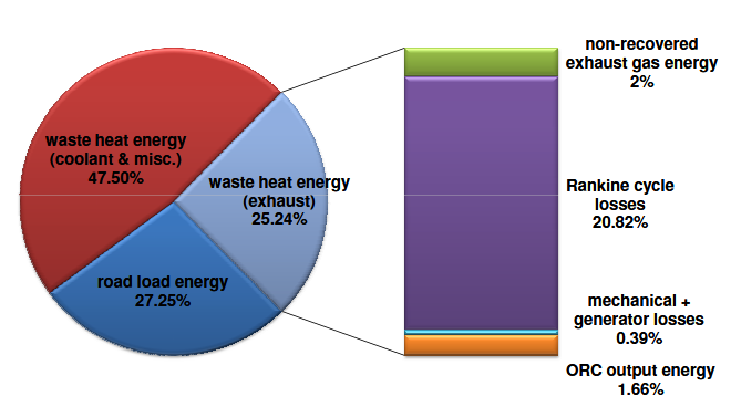
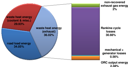
ORC system’s performance under different operating conditions was also discussed. When the system operates under low load, the average power is only 0.4kW (Figure 30), and the recovered energy accounts for 1.7% of the total fuel burned (Figure 31). Under steady-state operation at high speeds, the power reaches 1.9kW (Figure 32), recovering 2.4% of the fuel energy, which corresponds to a 7% reduction in fuel consumption [23]. There is no doubt that ORC has obvious advantages in long-distance driving, while the frequent engine start-stop in urban areas makes the system somewhat ineffective. However, the weight of the system is also a factor that cannot be ignored. The ORC system with an additional weight of 60kg leads to a reduction in the electric range by 1.9-2.1km under urban conditions, but the impact of weight is negligible under high-speed conditions (with only a 0.7km loss). The ORC has "operating condition complementarity" in PHEVs — that is, pure electric driving in urban areas avoids the inefficient range of the ORC, while activating waste heat recovery during high-speed driving enables the system to achieve an optimal solution. However, since the dynamic characteristics of exhaust temperature during the cold start phase (such as energy loss before catalyst light-off) are not considered, and the impact of the ORC on the thermal management of the aftertreatment system is not evaluated, the actual test results may deviate from the theoretical ones.
7. Conclusion
The paper analyzed 5 different examples to verify the feasibility of implementing energy recovery systems on automobiles.
1. TEGs can effectively transform waste heat generated by automobile exhaust into electrical energy. The effectiveness of this conversion process is significantly influenced by the generator's proximity to the heat source. The voltage will create 1.34 V and 0.98 V if the distance of the TEG is 80 cm and 96 cm from the heat source respectively, which indicate closer to the heat source create more voltage. However, TEGs face challenges as well. Current waste heat recovery systems don’t recover enough energy for electricity production. Hence, TEGs are not entirely feasible for power recovery.
2. E-Turbos showed good performance under different operating conditions including both stop-go urban roads and high-speed interstate highways. Under WLTC, the system successfully recovered 112Wh from 617Wh of exhaust energy, with a recovery efficiency of 18.1%. Under NEDC, it also recovered 54Wh, corresponding to an efficiency of 13.6%. Hence, these results support that it does improve overall system efficiency under various conditions.
3. The research on mechanical flywheels have verified the feasibility of using FESSs and the more complex power distribution. The acceleration performance of the flywheel hybrid has been improved by 42% compared to other models while maintaining moderate fuel economy. It adopts a lightweight design and common materials, simplifying the structure of the traditional flywheel power system and reducing costs. The climbing performance has been enhanced by 40%. This system has been applied to actual vehicles and other traffic roads. When actually applied to buses on all roads, it saves over 20% of fuel comprehensively. On racing cars, it saves charging time, improves driving efficiency, and helps teams win championships, proving the excellent feasibility of the flywheel power system in bringing economic benefits.
4. RBSs are a very prospective technology due the flexibility in installation and the amount of energy recovered. Studies showed that it can recover as many as 50% of the mechanical energy delivered to the wheels when tested in real-life conditions, and has potential for more on carefully planned-out routes.
5. Studies are continuing to try to find the way to utilize Rankine Cycle generators and ORC generators on small vehicles. Currently, the maximum energy recovered is 34% on Mack Trunk. The system was smaller than other editions, to be fit easily in the truck’s engine box.
Overall, it is recommended to implement at least one of the five automobile energy recovery systems: TEG, E-Turbo, mechanical flywheel, RBS and ORC generators to improve the energy efficiency of automotive vehicles. An RBS is most encouraged due to low upfront cost and more mature technology.
Author contribution
Zicheng ZHONG, Zhixing CHEN, Haolin PAN, Zichen XU and Kailiang YANG contributed equally to this work and should be considered co-first authors.
The authors declare that they have no known relevant interests of any kind that may be perceived to have influenced the work presented in this paper in any way.
References
[1]. A. H. Zarawi and S. S. Yi, “Maximizing Energy Efficiency: Harnessing Thermoelectric Power from Car Exhaust for Battery Recharge, ” Evol. Electr. Electron. Eng., vol. 5, no. 1, Art. no. 1, Apr. 2024.
[2]. D. Ö. Esen and M. Kaya, “EXPLORING THERMOELECTRIC GENERATION OF ELECTRICAL ENERGY FROM EXHAUST GAS HEAT: AN EXPERIMENTAL STUDY”.
[3]. G. Ehlin and E. Vandor, “Electrically Assisted Turbocharger: Modelling and Control Strategy”.
[4]. I. Arsie, A. Cricchio, C. Pianese, M. D. Cesare, and W. Nesci, “A Comprehensive Powertrain Model to Evaluate the Benefits of Electric Turbo Compound (ETC) in Reducing CO2 Emissions from Small Diesel Passenger Cars, ” presented at the SAE 2014 World Congress & Exhibition, SAE International, Apr. 2014. doi: 10.4271/2014-01-1650.
[5]. F. P. Brito et al., “Efficiency improvement of vehicles using temperature controlled exhaust thermoelectric generators, ” Energy Convers. Manag., vol. 203, p. 112255, Jan. 2020, doi: 10.1016/j.enconman.2019.112255.
[6]. C. C. Suciu, S. V. Igret, I. Vetres, and I. Ionel, “Review of the Integration of Hybrid Electric Turbochargers for Mass-Produced Road Vehicles, ” Energies, vol. 17, no. 6, Art. no. 6, Jan. 2024, doi: 10.3390/en17061484.
[7]. P. Dimitriou, R. Burke, Q. Zhang, C. Copeland, and H. Stoffels, “Electric Turbocharging for Energy Regeneration and Increased Efficiency at Real Driving Conditions, ” Appl. Sci., vol. 7, no. 4, p. 350, Apr. 2017, doi: 10.3390/app7040350.
[8]. A. Boretti, “Electric turbochargers in hydrogen internal combustion engines powered hybrid electric vehicles: Advancing performance, efficiency, and sustainability, ” Int. J. Hydrog. Energy, vol. 103, pp. 690–700, Feb. 2025, doi: 10.1016/j.ijhydene.2025.01.225.
[9]. N. Bernard, H. B. Ahmed, B. Multon, C. Kerzreho, J. Delamare, and F. Faure, “Flywheel energy storage systems in hybrid and distributed electricity generation, ” 2003.
[10]. S. M. Lukic, J. Cao, R. C. Bansal, F. Rodriguez, and A. Emadi, “Energy Storage Systems for Automotive Applications, ” IEEE Trans. Ind. Electron., vol. 55, no. 6, pp. 2258–2267, June 2008, doi: 10.1109/TIE.2008.918390.
[11]. B. Bolund, H. Bernhoff, and M. Leijon, “Flywheel energy and power storage systems, ” Renew. Sustain. Energy Rev., vol. 11, no. 2, pp. 235–258, Feb. 2007, doi: 10.1016/j.rser.2005.01.004.
[12]. H. L. Benford and M. B. Leising, “The Lever Analogy: A New Tool in Transmission Analysis, ” SAE Trans., vol. 90, pp. 429–437, 1981.
[13]. “Feasibility Analysis and Performance Evaluation of a Novel Power-Split Flywheel Hybrid Vehicle.” Accessed: July 22, 2025. [Online]. Available: https: //www.mdpi.com/1996-1073/11/7/1744
[14]. “Flywheel Energy Storage for Automotive Applications.” Accessed: July 22, 2025. [Online]. Available: https: //www.mdpi.com/1996-1073/8/10/10636
[15]. K. Van Berkel, T. Hofman, B. Vroemen, and M. Steinbuch, “Optimal energy management for a flywheel-based hybrid vehicle, ” in Proceedings of the 2011 American Control Conference, San Francisco, CA: IEEE, June 2011, pp. 5255–5260. doi: 10.1109/acc.2011.5990820.
[16]. G. Cong, N. Dawen, G. Linfu, X. Qicheng, and M. Shujian, “Simulation Research on Regenerative Braking Control Strategy of Hybrid Electric Vehicle, ” Energies, doi: 10.3390/en14082202.
[17]. “An overview of regenerative braking systems, ” J. Energy Storage, vol. 52, p. 105033, Aug. 2022, doi: 10.1016/j.est.2022.105033.
[18]. S. Bai and C. Liu, “Overview of energy harvesting and emission reduction technologies in hybrid electric vehicles, ” Renew. Sustain. Energy Rev., vol. 147, p. 111188, Sept. 2021, doi: 10.1016/j.rser.2021.111188.
[19]. J. Kropiwnicki and T. Gawłas, “Energy efficiency of a car driving with regenerative braking, ” Combust. Engines, July 2025, doi: 10.19206/CE-207152.
[20]. S. Dabral, S. Basak, and C. Chakraborty, “Regenerative Braking Efficiency Enhancement using Pole-Changing Induction Motor, ” in IECON 2022 – 48th Annual Conference of the IEEE Industrial Electronics Society, Oct. 2022, pp. 1–6. doi: 10.1109/IECON49645.2022.9968341.
[21]. R. Capata and C. Toro, “Feasibility analysis of a small-scale ORC energy recovery system for vehicular application, ” Energy Convers. Manag., vol. 86, pp. 1078–1090, Oct. 2014, doi: 10.1016/j.enconman.2014.06.024.
[22]. S. H. Kang, “Design and experimental study of ORC (organic Rankine cycle) and radial turbine using R245fa working fluid, ” Energy, vol. 41, no. 1, pp. 514–524, May 2012, doi: 10.1016/j.energy.2012.02.035.
[23]. P. Skarke, S. Midlam-Mohler, and M. Canova, “Waste Heat Recovery From Internal Combustion Engines: Feasibility Study on an Organic Rankine Cycle With Application to the Ohio State EcoCAR PHEV, ” in ASME 2012 Internal Combustion Engine Division Fall Technical Conference, Vancouver, BC, Canada: American Society of Mechanical Engineers, Sept. 2012, pp. 609–615. doi: 10.1115/icef2012-92018.
Cite this article
Zhong,Z.;Chen,Z.;Pan,H.;Xu,Z.;Yang,K. (2025). Implementation Feasibility and Efficiency of Automobile Energy Recovery Systems. Applied and Computational Engineering,188,108-131.
Data availability
The datasets used and/or analyzed during the current study will be available from the authors upon reasonable request.
Disclaimer/Publisher's Note
The statements, opinions and data contained in all publications are solely those of the individual author(s) and contributor(s) and not of EWA Publishing and/or the editor(s). EWA Publishing and/or the editor(s) disclaim responsibility for any injury to people or property resulting from any ideas, methods, instructions or products referred to in the content.
About volume
Volume title: Proceedings of CONF-MCEE 2026 Symposium: Advances in Sustainable Aviation and Aerospace Vehicle Automation
© 2024 by the author(s). Licensee EWA Publishing, Oxford, UK. This article is an open access article distributed under the terms and
conditions of the Creative Commons Attribution (CC BY) license. Authors who
publish this series agree to the following terms:
1. Authors retain copyright and grant the series right of first publication with the work simultaneously licensed under a Creative Commons
Attribution License that allows others to share the work with an acknowledgment of the work's authorship and initial publication in this
series.
2. Authors are able to enter into separate, additional contractual arrangements for the non-exclusive distribution of the series's published
version of the work (e.g., post it to an institutional repository or publish it in a book), with an acknowledgment of its initial
publication in this series.
3. Authors are permitted and encouraged to post their work online (e.g., in institutional repositories or on their website) prior to and
during the submission process, as it can lead to productive exchanges, as well as earlier and greater citation of published work (See
Open access policy for details).
References
[1]. A. H. Zarawi and S. S. Yi, “Maximizing Energy Efficiency: Harnessing Thermoelectric Power from Car Exhaust for Battery Recharge, ” Evol. Electr. Electron. Eng., vol. 5, no. 1, Art. no. 1, Apr. 2024.
[2]. D. Ö. Esen and M. Kaya, “EXPLORING THERMOELECTRIC GENERATION OF ELECTRICAL ENERGY FROM EXHAUST GAS HEAT: AN EXPERIMENTAL STUDY”.
[3]. G. Ehlin and E. Vandor, “Electrically Assisted Turbocharger: Modelling and Control Strategy”.
[4]. I. Arsie, A. Cricchio, C. Pianese, M. D. Cesare, and W. Nesci, “A Comprehensive Powertrain Model to Evaluate the Benefits of Electric Turbo Compound (ETC) in Reducing CO2 Emissions from Small Diesel Passenger Cars, ” presented at the SAE 2014 World Congress & Exhibition, SAE International, Apr. 2014. doi: 10.4271/2014-01-1650.
[5]. F. P. Brito et al., “Efficiency improvement of vehicles using temperature controlled exhaust thermoelectric generators, ” Energy Convers. Manag., vol. 203, p. 112255, Jan. 2020, doi: 10.1016/j.enconman.2019.112255.
[6]. C. C. Suciu, S. V. Igret, I. Vetres, and I. Ionel, “Review of the Integration of Hybrid Electric Turbochargers for Mass-Produced Road Vehicles, ” Energies, vol. 17, no. 6, Art. no. 6, Jan. 2024, doi: 10.3390/en17061484.
[7]. P. Dimitriou, R. Burke, Q. Zhang, C. Copeland, and H. Stoffels, “Electric Turbocharging for Energy Regeneration and Increased Efficiency at Real Driving Conditions, ” Appl. Sci., vol. 7, no. 4, p. 350, Apr. 2017, doi: 10.3390/app7040350.
[8]. A. Boretti, “Electric turbochargers in hydrogen internal combustion engines powered hybrid electric vehicles: Advancing performance, efficiency, and sustainability, ” Int. J. Hydrog. Energy, vol. 103, pp. 690–700, Feb. 2025, doi: 10.1016/j.ijhydene.2025.01.225.
[9]. N. Bernard, H. B. Ahmed, B. Multon, C. Kerzreho, J. Delamare, and F. Faure, “Flywheel energy storage systems in hybrid and distributed electricity generation, ” 2003.
[10]. S. M. Lukic, J. Cao, R. C. Bansal, F. Rodriguez, and A. Emadi, “Energy Storage Systems for Automotive Applications, ” IEEE Trans. Ind. Electron., vol. 55, no. 6, pp. 2258–2267, June 2008, doi: 10.1109/TIE.2008.918390.
[11]. B. Bolund, H. Bernhoff, and M. Leijon, “Flywheel energy and power storage systems, ” Renew. Sustain. Energy Rev., vol. 11, no. 2, pp. 235–258, Feb. 2007, doi: 10.1016/j.rser.2005.01.004.
[12]. H. L. Benford and M. B. Leising, “The Lever Analogy: A New Tool in Transmission Analysis, ” SAE Trans., vol. 90, pp. 429–437, 1981.
[13]. “Feasibility Analysis and Performance Evaluation of a Novel Power-Split Flywheel Hybrid Vehicle.” Accessed: July 22, 2025. [Online]. Available: https: //www.mdpi.com/1996-1073/11/7/1744
[14]. “Flywheel Energy Storage for Automotive Applications.” Accessed: July 22, 2025. [Online]. Available: https: //www.mdpi.com/1996-1073/8/10/10636
[15]. K. Van Berkel, T. Hofman, B. Vroemen, and M. Steinbuch, “Optimal energy management for a flywheel-based hybrid vehicle, ” in Proceedings of the 2011 American Control Conference, San Francisco, CA: IEEE, June 2011, pp. 5255–5260. doi: 10.1109/acc.2011.5990820.
[16]. G. Cong, N. Dawen, G. Linfu, X. Qicheng, and M. Shujian, “Simulation Research on Regenerative Braking Control Strategy of Hybrid Electric Vehicle, ” Energies, doi: 10.3390/en14082202.
[17]. “An overview of regenerative braking systems, ” J. Energy Storage, vol. 52, p. 105033, Aug. 2022, doi: 10.1016/j.est.2022.105033.
[18]. S. Bai and C. Liu, “Overview of energy harvesting and emission reduction technologies in hybrid electric vehicles, ” Renew. Sustain. Energy Rev., vol. 147, p. 111188, Sept. 2021, doi: 10.1016/j.rser.2021.111188.
[19]. J. Kropiwnicki and T. Gawłas, “Energy efficiency of a car driving with regenerative braking, ” Combust. Engines, July 2025, doi: 10.19206/CE-207152.
[20]. S. Dabral, S. Basak, and C. Chakraborty, “Regenerative Braking Efficiency Enhancement using Pole-Changing Induction Motor, ” in IECON 2022 – 48th Annual Conference of the IEEE Industrial Electronics Society, Oct. 2022, pp. 1–6. doi: 10.1109/IECON49645.2022.9968341.
[21]. R. Capata and C. Toro, “Feasibility analysis of a small-scale ORC energy recovery system for vehicular application, ” Energy Convers. Manag., vol. 86, pp. 1078–1090, Oct. 2014, doi: 10.1016/j.enconman.2014.06.024.
[22]. S. H. Kang, “Design and experimental study of ORC (organic Rankine cycle) and radial turbine using R245fa working fluid, ” Energy, vol. 41, no. 1, pp. 514–524, May 2012, doi: 10.1016/j.energy.2012.02.035.
[23]. P. Skarke, S. Midlam-Mohler, and M. Canova, “Waste Heat Recovery From Internal Combustion Engines: Feasibility Study on an Organic Rankine Cycle With Application to the Ohio State EcoCAR PHEV, ” in ASME 2012 Internal Combustion Engine Division Fall Technical Conference, Vancouver, BC, Canada: American Society of Mechanical Engineers, Sept. 2012, pp. 609–615. doi: 10.1115/icef2012-92018.