


1. Introduction
The world is undergoing rapid population growth which corresponds to increased demands for automobiles. The rapid growth of the automobiles has been associated with numerous benefits; however, it has also brought about significant environmental deterioration of our planet [1]. Within the European Union (EU), emissions from road transport are estimated 23% of the total CO₂ levels [2]. In recent years, manufacturers have realized that the application of Energy recovery systems (ERSs) is an effective method to improve automobiles’ efficiency and reduce CO₂ emissions. ERSs for automotive applications are defined as the techniques to recover the energy of the vehicle that otherwise would have been wasted. The recovered energy can be stored and then used when necessary, reducing the need for fuel, and therefore improving the overall efficiency of the vehicle [3]. In the present review article, ERSs are firstly classified according to the source of energy to be recovered: (i) energy from exhaust gases, (ii) energy from vehicle inertia and so on [3]. To recover the energy from exhaust gases, we have methods like thermoelectric, Rankine cycle and electric turbochargers. For recovering the kinetic energy from vehicle inertia, we have methods like regenerative braking and mechanical flywheel. Given these diverse energy recovery methods, this review aims to perform a comparative analysis to assess their effectiveness in significantly reducing fuel consumption in automotive vehicles and to identify the most efficient among them based on performance under various driving conditions.
The growing popularity of hybrid electric vehicles (HEVs) is fueled by rising fuel costs and environmental concerns. HEVs combine an internal combustion engine with an electric motor, and offer improved fuel economy and lower emissions. This paper describes a kinetic energy recovery system suitable for internal combustion engine vehicles. The supercapacitor is the unique energy storage device of this system. The core of the system design lies in storing kinetic energy through the supercapacitor during the braking stage, and then delivering the stored energy to the MGU for acceleration, thereby reducing the power demand of the thermal engine. This study also focuses on regenerative braking, a method that captures kinetic energy during deceleration to boost efficiency. This study, through the Autonomie simulation software, focused on analyzing the efficiency performance of the transmission system during the regenerative braking process for two hybrid power system architectures [4]. We also find that it significantly enhances energy recovery, especially in city driving. The results support the potential of regenerative braking to improve sustainability in vehicle design.
Mechanical flywheel energy storage systems (FESS) have historically been explored for automotive applications due to their potential for high power density and long cycle life. Early implementations, such as the Oerlikon gyrobuses of the 1940s, utilized heavy steel rotors [5]. While demonstrating the concept's viability, these systems were hampered by high energy consumption, significant maintenance needs, and overall weight issues, leading to their eventual retirement [6]. The core challenge lay in the trade-off between inertial mass for energy storage and rotational speed for power, with traditional materials limiting performance. Subsequent research focused on overcoming these limitations through advanced materials like carbon composites and improved bearing technologies, such as magnetic levitation, to enable higher rotational speeds and reduce losses [7,8]. These developments aimed to create FESS that were more suitable for the frequent charge-discharge cycles and packaging constraints of modern vehicles, paving the way for contemporary assessments of their fuel-saving potential and integration feasibility.
Against global carbon neutrality goals (EU: 55% greenhouse gas (GHG) cut by 2030; China: carbon neutrality by 2060), the transportation sector—accounting for ~20% of global CO₂ emissions—faces urgent pressure to enhance energy efficiency, driven by stricter rules like China's 6 Real Driving Emission (RDE). Internal combustion engines (ICEs) remain dominant in passenger and heavy-duty vehicles but waste 35–50% of fuel energy as exhaust heat, making waste heat recovery (WHR) critical—yet existing WHR technologies have unresolved flaws. Exhaust Heat Recovery Systems (EHRS) cut fuel use by 3%–7% by speeding engine warm-up [9], ideal for cold starts (a high-emission scenario), but lack full-vehicle data under real driving [10]. Thermoelectric Generators (TEG) generate electricity via the Seebeck effect but suffer performance drops in dynamic driving (e.g., acceleration-induced temperature fluctuations [11]) and high costs [12]; while module layout optimization boosts heavy-duty efficiency [13], passenger car use is unaddressed. Organic Rankine Cycles (ORC) excel at low-grade heat recovery (stable in diesel tests [14,15]) but struggle in passenger cars due to space limits and unsteady exhaust heat [16,17]. Cold starts worsen emissions: -7°C NOₓ is 2.3–6x higher than 23°C [18], HC surges during deceleration [19], and energy loss distribution is unclear [20], failing RDE standards. Two gaps persist: insufficient EHRS cold-start full-vehicle data, and unoptimized Inverted Brayton Cycle (IBC)-steam injection integration. This study solves these with two tests: (1) EHRS full-vehicle experiments under cold-start NEDC (25°C/-7°C), monitoring coolant temperature, fuel use, and emissions (THC, NOₓ); (2) optimizing steam-injected IBC (e.g., turbine size, steam flow) to boost fuel economy. It aims to validate EHRS and improve IBC, supporting China's 6 RDE and carbon neutrality.
Internal combustion engines exhibit relatively low thermal efficiency, with 35–45% of the fuel energy typically lost through exhaust gases [21]. Recovering this waste heat has therefore become an important research focus for improving vehicle fuel economy and reducing emissions. Among different recovery methods, the Organic Rankine Cycle (ORC) has received considerable attention because of its adaptability, stable operation, and suitability for low- and medium-grade heat sources [21]. Early investigations mainly addressed heat source characteristics, working fluid selection, and component performance, showing measurable efficiency gains under steady operating conditions [21]. However, these studies often neglected the transient behavior of engines in real driving cycles, where frequent fluctuations in load and exhaust temperature significantly influence system performance [22]. More recent work highlights that ORC systems perform better in stable high-speed conditions, while their benefits diminish in urban stop-and-go driving [21,22]. To better capture these effects, integrated vehicle–ORC models and multi-objective optimization frameworks have been proposed, enabling the evaluation of thermodynamic, economic, and environmental trade-offs under realistic driving conditions [22].
Internal combustion engines dissipate approximately 30% of fuel energy as exhaust heat, representing a significant opportunity for efficiency gains through waste heat recovery (WHR). Turbocharging systems, particularly exhaust gas turbochargers (EGT), have long been a primary method to harness this energy, improving power density and enabling engine downsizing. However, conventional EGTs face inherent limitations, including transient response lag ("turbo lag") during acceleration and restricted low-speed torque due to insufficient exhaust flow. These limitations constrain overall engine efficiency and drivability. Electrically assisted turbocharger (ETC) technology emerged as a promising solution to overcome these constraints by integrating an electric motor/generator directly onto the turbocharger shaft. Early research by Hopmann and Algrain [23] pioneered the concept, demonstrating its potential for fuel savings. subsequent work explored diverse ETC architectures, including integrated shaft-mounted motor-compressor-turbine units [24] and configurations with a separate electric compressor [25]. Control strategies became a critical focus, with Divekar et al. [26] developing air-to-fuel ratio (-based controllers for coordinated operation. Research expanded into passenger car applications, with Arsie et al. [27] investigating ETC's role in assisting electrical loads without energy storage. Despite these developments, significant challenges remained, particularly regarding maximizing exhaust energy utilization efficiency under real-world driving conditions and ensuring robust charge sustainability without compromising drivability. Therefore, systematic evaluation of ETC's energy-saving potential across diverse operational scenarios - including transient response highway driving, and varying loads - is essential to bridge the gap between theoretical promise and practical implementation. This review synthesizes recent advancements to address these critical aspects.
This article aims to explore five significant methods for enhancing energy recovery in automobiles. By analyzing each method, we will assess its impact on improving the energy recovery efficiency of automobiles and identify the factors that influence this efficiency. The primary objective is to determine whether enhancing the efficiency of energy recovery systems can lead to a reduction in fuel consumption. Furthermore, the paper will evaluate which of these methods is the most efficient. Based on a comprehensive efficiency evaluation, the energy recovery method utilizing the Rankine cycle is presumed to be more efficient than regenerative braking, electric turbochargers, mechanical flywheels, and thermoelectric methods.
2. Regenerative braking
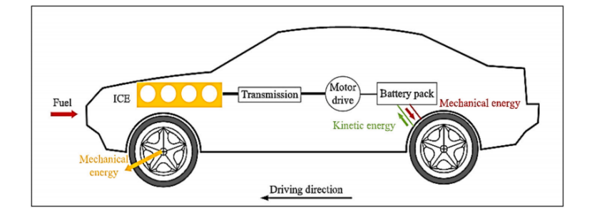
Regenerative braking systems are kinetic energy recovery systems designed to recuperate a portion of the kinetic energy that would otherwise be dissipated as heat during vehicle braking, typically through friction-based brake pads [1]. These systems work by converting the vehicle's kinetic energy into a storable form via components like motor/generator units and energy storage systems Fig.1, which can then be reused for vehicle propulsion or to charge onboard energy storage [28]. RBSs are integrated into various vehicles, including electric vehicles (EVs), hybrid electric vehicles (HEVs), and even some internal combustion engine vehicles (ICEVs), aiming to improve energy efficiency, reduce fuel consumption, and lower emissions. Their operation is governed by control strategies that manage the distribution of braking force between regenerative and friction brakes, ensuring safety, stability, and optimal energy recovery. The effectiveness of RBSs depends on factors like vehicle dynamics, road conditions, and the performance of associated control systems, which must balance energy recovery with braking safety and comfort [29].
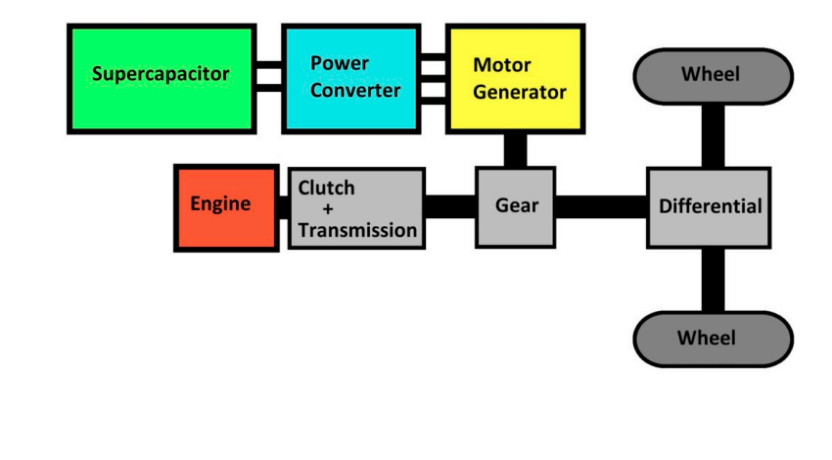
In a 2020 study, Emiliano Pipitone and Gianpaolo Vitale introduced an electric kinetic energy recovery system (e-KERS) for internal combustion engine vehicles (ICEVs), which utilizes supercapacitors as the sole energy storage element. The authors propose and describe an electric kinetic energy recovery system for internal combustion engine vehicles [30]. The structure is as shown in Fig. 2. To evaluate the system's performance, the study employs a Volkswagen Golf 1.4 TSI sedan as the test subject Table 1, conducting numerical simulations based on MATLAB Simulink. Two urban driving cycles, ECE-15 and Artemis urban, are adopted, taking into account the actual efficiency, power, and energy constraints of each system component. By calculating metrics such as energy recovery efficiency, energy saving rate, loss of load probability (LOLP), and loss of energy probability (LOEP), the study analyzes the performance of KERS with different power specifications under the two driving cycles. Additionally, the economic benefits and payback period are assessed based on the average gasoline price in Europe.
|
Item |
Value |
|
Brand and model |
Volkswagen Golf 1.4 TSI |
|
Segment |
C – Medium cars |
|
Reference mass [kg] |
1315 |
|
Engine displacement [L] |
1.39 |
|
Maximum output power [kW] |
90 |
|
Homologation |
Euro 5 |
|
Drag coefficient |
0.280 |
|
Frontal surface area [ |
2.63 |
|
Fuel |
Gasoline |
|
Fuel LHV [MJ |
43.4 |
|
Fuel density [kg |
730 |
|
Tyres |
205/55R16 |
|
Wheel radius [m] |
0.316 |
|
Differential gear ratio |
3.65 |
Supercapacitors are chosen as energy storage components because of their high power density and rapid charging and discharging capabilities, making them suitable for quickly absorbing and releasing energy during braking and acceleration. A detailed mathematical model was developed to simulate the performance of e-KERS. The model takes into account the actual efficiency of each component as well as the power and energy limitations. Specifically, it includes the charge and discharge characteristics of supercapacitors, the power output and input limits of motor-generator units (MGUs), and the efficiency of power converters, etc.
The implementation of the electric Kinetic Energy Recovery System (e-KERS) in internal combustion engine vehicles (ICEVs) has been shown to significantly enhance vehicle efficiency and fuel economy. Simulations across two urban driving cycles, ECE-15 and Artemis urban, demonstrated energy recovery efficiencies ranging from 38.8% to 54.2% and energy savings between 16.0% and 24.1%. These improvements directly translate to reduced fuel consumption and lower CO₂ emissions. For instance, the most effective configuration (KERS4) in the Artemis urban cycle achieved a 24.1% reduction in energy demand, corresponding to fuel savings of approximately 2.48 L per 100 km and a cost saving of 3.66 € per 100 km. Over 100,000 km, this results in a total fuel cost saving of around 3,660 € and a CO₂ emission reduction of 18.2 tons.
|
Power converter specifications for each of the four KERS considered |
||||
|
KERS1 |
KERS2 |
KERS3 |
KERS4 |
|
|
Peak motor power [kW] |
11.0 |
14.0 |
24.0 |
30.0 |
|
Max output power |
16.56 |
21.60 |
43.20 |
57.60 |
|
Max current |
371 |
484 |
968 |
1290 |
|
Max efficiency |
0.930 |
0.930 |
0.930 |
0.930 |
|
Max input power |
17.8 |
23.2 |
46.5 |
61.9 |
|
Weight [kg] |
2.30 |
3.00 |
6.00 |
8.00 |
|
Commercial cost [€] |
360 |
469 |
938 |
1251 |
|
Overall cost and weight of the four KERS considered |
||||
|
Specification |
KERS1 |
KERS2 |
KERS3 |
KERS4 |
|
Peak motor power [kW] |
11.0 |
14.0 |
24.0 |
30.0 |
|
Commercial cost [€] |
1488 |
1615 |
2146 |
2459 |
|
Weight [kg] |
26.8 |
27.5 |
36.4 |
38.4 |
|
Weight increment [%] |
2.0% |
2.1% |
2.8% |
2.9% |
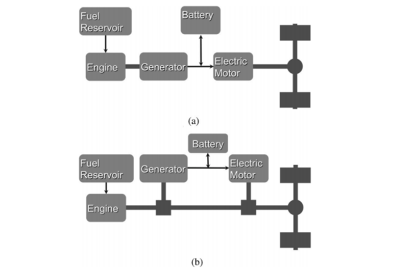
In 2016, Andrew J. Stratton aims to explore the impact of regenerative braking on the fuel economy of HEVs, especially the potential benefits of regenerative braking technology for future vehicles after reducing mass, lowering rolling resistance and air resistance [4]. The study employed the Autonomie automotive simulation software package to simulate the fuel economy of two hybrid architectures (series and power-split), Fig. 3, under three different operating conditions: urban (FTP75), highway (HWFET), and aggressive driving (US06). The FTP75 schedule simulates urban driving, consisting of speed cycles that were actually recorded in commuter traffic in Los Angeles, and the HWFET simulates highway driving. The US06 cycle is part of the supplemental federal test procedure (SFTP), which was designed to address the shortcomings of the FTP75. The EPA determined that the urban schedule did not prescribe rapid enough accelerations, whilst the highway schedule did not prescribe sufficiently high speeds to be representative of common driving habits. Hence, the US06 schedule was designed to simulate a more aggressive driving style Table 2. It is assumed that these three driving scenarios span the popular actual driving approaches, and therefore a general conclusion from this study can be drawn as to whether the impact of regenerative braking overall is going to increase. By comparing the fuel economy of HEV architectures with regenerative braking enabled and disabled, the benefits of regenerative braking in different driving scenarios were studied and analyzed.
|
Cycle |
FTP75 |
HWFET |
US06 |
|
Average speed (overall) [m/s] |
9.45 |
21.60 |
21.46 |
|
Average speed (Non-idle) [m/s] |
11.45 |
21.69 |
23.00 |
|
Maximum speed [m/s] |
25.32 |
26.77 |
35.86 |
|
Average acceleration [m/s²] |
0.44 |
0.16 |
0.60 |
|
Maximum acceleration [m/s²] |
1.48 |
1.43 |
4.17 |
|
Average deceleration [m/s²] |
-0.36 |
-0.18 |
-0.59 |
|
Maximum deceleration [m/s²] |
-3.46 |
-2.85 |
-3.20 |
|
Duration of cycle [s] |
1877 |
765 |
600 |
|
Length of cycle [km] |
17.76 |
16.50 |
12.88 |
|
Time at idle [s] |
328 |
3.1 |
40.2 |
|
% of Cycle at Idle |
17.5% |
0.41% |
6.7% |
This study employed simulation techniques to analyze the impact of regenerative braking on the fuel economy of hybrid electric vehicles (HEVs). The results revealed that regenerative braking significantly enhances fuel economy, particularly in urban driving scenarios (FTP75), where the impact factor (IRB) was the highest Fig. 4.
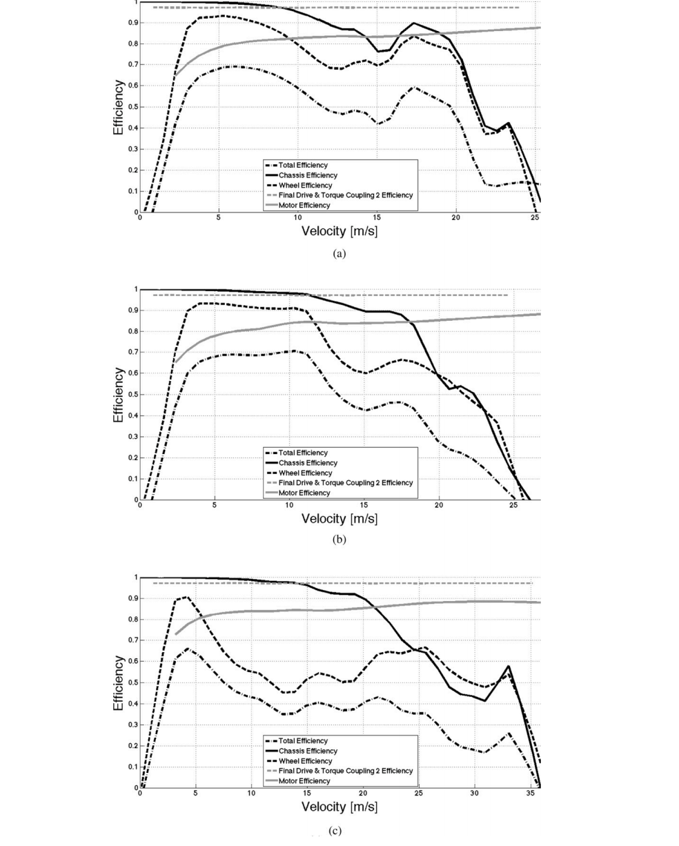
In contrast, the benefits in highway (HWFET) and aggressive driving (US06) scenarios were relatively modest. However, the study projects that reductions in vehicle rolling resistance and air resistance will markedly amplify these benefits in the future. Interestingly, while decreasing vehicle mass generally improves efficiency, it was found to have a detrimental effect on regenerative braking efficiency when the reduction exceeded 25%. This is because the recoverable kinetic energy, which is directly proportional to mass, diminishes. Nonetheless, the study demonstrated that reducing rolling resistance and air resistance can enhance the energy recovery efficiency of regenerative braking. In highway driving, where speeds are higher, air resistance has a more pronounced impact, making its reduction crucial for boosting regenerative braking efficiency. Conversely, in urban settings, frequent braking and lower average speeds optimize energy recovery, thereby substantially improving fuel economy. In summary, regenerative braking technology holds substantial energy-saving potential for both current and future HEVs. Despite the negative impact of mass reduction, the efficiency of regenerative braking can be significantly enhanced by reducing rolling and air resistance. Thus, regenerative braking will continue to be a pivotal technology in the evolution of HEVs, especially in urban environments, where its fuel economy benefits are most pronounced. The study concluded that the impact factor (IRB) for urban driving scenarios was found to be 1.25, indicating a 25% improvement in fuel economy compared to non-regenerative braking scenarios. This substantial increase underscores the significant potential of regenerative braking to enhance energy efficiency and reduce emissions in HEVs, positioning it as a key strategy for sustainable transportation.
3. Mechanical flywheel
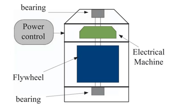
A mechanical flywheel is a mechanical device specifically designed to store rotational energy efficiently, and its storage capacity is proportional to the square of its rotational speed. The energy stored in the flywheel can be changed by increasing or decreasing its rotational speed, and the higher the speed, the more energy stored. By applying a torque aligned with its axis of symmetry, the flywheel can be charged, and when the flywheel releases energy, it is also output in the form of torque [31]. Flywheel Energy Storage System (FESS), as shown in Figure 5, is an electromechanical energy storage system that can exchange electrical power with the electric network. Unlike other storage systems such as the Battery Energy Storage System (BESS), FESS is an environmentally-friendly short- or medium-term energy storage system, which has the capability of numerous charge and discharge cycles [32]. These characteristics above make the FESS an ideal secondary storage technology for a conventional internal combustion engine vehicle (ICEV) since it is able to store the energy purely in mechanical form, avoiding the two-stage conversion losses of electro-chemical-electric paths in BESS [33]. A mechanical flywheel, as the name suggest, is a mechanical device specifically designed to store rotational energy efficiently, and its storage capacity is proportional to the square of its rotational speed. The energy stored in the flywheel can be changed by increasing or decreasing its rotational speed by applying a torque aligned with its axis of symmetry. Based on mechanical flywheels, the Flywheel Energy Storage System (FESS) is an electromechanical energy storage system that can exchange electrical power with the electric network. Unlike other storage systems such as the Battery Energy Storage System (BESS), FESS is an environmentally-friendly short- or medium-term energy storage system, which has the capability of numerous charge and discharge cycles. These characteristics above make the FESS an ideal secondary storage technology for a conventional internal combustion engine vehicle (ICEV) since it is able to store the energy purely in mechanical form, avoiding the two-stage conversion losses of electro-chemical-electric paths in BESS. Furthermore, future materials (e.g., carbon nanotubes) development could raise rotor energy density and make FESS even more efficient.
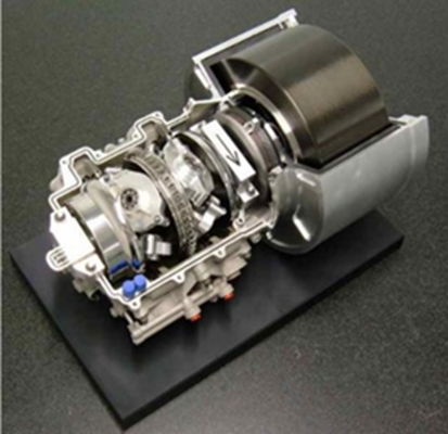
Hedlund et al. [34] present a comprehensive review of FESS in automotive applications, focusing on their power density, cycle life, cost competitiveness and fuel savings. Their review covers rotor design trade-offs, bearing technologies (comparing mechanical and magnetic), and power transfer mechanisms (comparing mechanical CVT and electrical PMSM coupling). Their methodological approach involves a systematic analysis and comparison of existing flywheel systems from both industry and academia. The study also examines various applications, from urban buses to Formula 1 Kinetic Energy Recovery Systems (KERS) as shown in Figure 6, with data gathered from technical specifications, performance tests, and case studies of deployed systems.
The results of the review indicate that flywheels excel in high-power applications. For example, flywheel systems were found to achieve specific power up to 2.2 kW/kg and specific energy up to 8.3 Wh/kg, as shown in Table 4, outperforming supercapacitors in comparable vehicular applications. This high power density makes them particularly suitable for frequent charge/discharge cycles like urban driving scenarios. The study also reports that in the New European Driving Cycle (NEDC) test cycle, a 1.7-ton saloon car can save 18% of fuel consumption, and in the Federal Test Program (FTP) driving cycle in the United States, a 2.6-ton SUV can save 35% of fuel consumption [35]. Similar successful deployments confirm flywheels’ fuel-saving potential across diverse vehicles: 45% for London buses, and 10% for excavators. Flywheels can reduce battery strain, enabling downsizing of energy-dense packs. However, energy density remains lower than that of Li-ion, and self-discharge is higher. Future materials (e.g., carbon nanotubes) could raise rotor energy density to more than 500 Wh/kg. The conclusion points out that flywheels are mature for mass-market deployment, particularly as power buffers in hybrid drivetrains, offering cost-effective, durable solutions for fuel and emissions reduction. It achieves a fuel saving potential of approximately 20% in NEDC test cycle, highlighting its effectiveness.
|
Type |
Flywheel system |
EDLC system |
Li-ion battery system |
|
Manufacturer |
GKN |
Maxwell Boostcap |
A123Systems |
|
Rated power |
120 kW |
120 kW |
120 kW |
|
Energy capacity |
456 Wh |
647 Wh |
26,400 Wh |
|
Cycle life time |
>106 |
∼106 |
∼103 |
|
Specific energy |
8.3 Wh/kg |
1.75 Wh/kg |
110 Wh/kg |
|
Specific power |
2200 W/kg |
320 W/kg |
500 W/kg |
|
System weight |
55 kg |
370 kg |
240 kg |
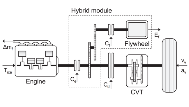
Research from Van Berkel et al. [37] supported the results of mechanical flywheel in reducing vehicle fuel consumption. They investigate a low-cost mechanical hybrid powertrain utilizing a steel flywheel and a push-belt Continuously Variable Transmission (CVT), devoid of electrical components for hybridization. The aim of their study is to minimize fuel consumption while maintaining driving comfort, leveraging operations like brake energy recovery and engine shut-off. Their method involves developing a dynamic model of the hybrid drivetrain components, including the Internal Combustion Engine (ICE), flywheel, CVT, clutches, and vehicle dynamics. The core of their approach is to formulate an Energy Management Strategy (EMS) problem as a discrete-time optimal control problem. This problem is designed to find the optimal sequence of driving modes (e.g., flywheel drive, flywheel charging, engine drive) and engine torque commands. They apply Dynamic Programming (DP) to solve this optimization problem over predefined driving cycles (e.g., NEDC, FTP75), incorporating comfort constraints to avoid frequent gear shifts and undesirable engine noise (e.g., limiting frequent mode shifts, avoiding engine noise mismatch). The simulation setup models the drivetrain components (ICE, flywheel, CVT, vehicle dynamics) and executes the DP algorithm over driving cycle inputs (e.g., velocity profile) to compute optimal control sequences and resulting fuel consumption. As shown in Fig. 7, the study models the entire system topology and signal flow for this purpose. They then simulate their system over five standard driving cycles (JP1015, JC08, NEDC, FTP75, and a custom aggressive cycle called Hurk).
The simulation results demonstrate that the proposed flywheel-based hybrid system achieves fuel savings, as shown in Table 5, ranging from 20% to 39% across five different driving cycles compared to a conventional baseline vehicle. The highest fuel savings, approximately 39%, were observed on the aggressive Hurk driving cycle. This is attributed to the frequent acceleration and deceleration events in this cycle, which maximize the benefits of flywheel energy reuse. The lowest savings, approximately 20%, were achieved on the New European Driving Cycle (NEDC). The NEDC contains longer periods of highway-style cruising where the flywheel is utilized less frequently, therefore, causing the efficiency of energy recovery. The optimal EMS uses the flywheel to launch the vehicle, charges it during low-speed acceleration, and discharges it during cruising or braking. The DP-based controller successfully avoids uncomfortable mode shifts, such as engine noise mismatches or rapid transitions, by constraining shift frequency and synchronization time. This proves that the practicability of the strategy goes beyond simple fuel minimization and also ensures the comfort of the vehicle. The study not only provides a benchmark for potential real-time controller development and highlights the viability of cost-effective hybridization, but also concludes that a significant fuel saving of 20-39% is achievable with a purely mechanical flywheel hybrid system. In particular, the 20% fuel saving under NEDC is also consistent with the results from Hedlund et al. [7], which well supports this conclusion.
|
Driving cycle |
Fuel consumption (l/100km) |
||
|
BL |
DP1 |
DP2 |
|
|
JP1015 |
6.06 |
3.82 (-37.0%) |
3.88 (-36.0%) |
|
JC08 |
5.76 |
3.87 (-32.8%) |
3.89 (-32.5%) |
|
NEDC |
5.75 |
4.60 (-20.0%) |
4.63 (-19.5%) |
|
FTP75 |
5.48 |
3.99 (-27.2%) |
4.02 (-26.6%) |
|
Hurk |
7.91 |
4.78 (-39.6%) |
4.82 (-39.1%) |
4. Thermoelectric
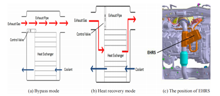
Vehicle exhaust heat recovery (EHR) technologies target reclaiming waste thermal energy from exhaust gases, thereby reducing fuel consumption and enhancing overall energy utilization. As shown in Fig. 8, EHR physically works by leveraging a gas-liquid heat exchanger to transfer exhaust heat directly to engine coolant, accelerating warm-up and reducing the duration of low-temperature, inefficient combustion.
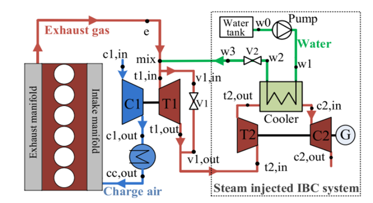
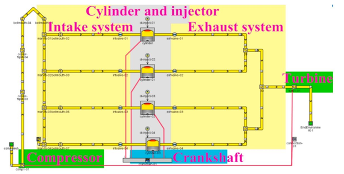
Another version is the steam-injected inverted Brayton cycle (IBC), which physically works by integrating pressure energy recovery via IBC turbines downstream of turbochargers with steam injection using waste heat from IBC coolers, as shown in Fig. 9, to create a cascaded energy cycle that converts residual exhaust enthalpy into mechanical work. The benefits of these systems include reducing fuel consumption and enhancing overall energy utilization. A core metric for evaluating EHR systems is the overall efficiency gain—the ratio of recovered energy (e.g., converted to mechanical work or used for thermal management) to the total waste heat available in exhaust streams. These systems directly address the challenge of low ICE efficiency (typically 30–40% of fuel energy converted to work, with ~30% lost as exhaust heat). However, challenges such as system complexity, cost-effectiveness, and integration with transient engine operations still need to be overcome to fully bridge this gap via thermal energy reuse.
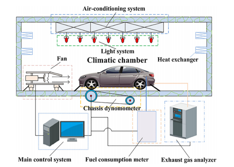
In 2019, Shen et al. investigated the effects of an EHRS designed to accelerate coolant heating under cold-start NEDC conditions, reducing inefficiencies from prolonged low-temperature combustion, incomplete fuel vaporization, and extended engine warm-up [14]. The general topic of the paper is the impact of EHRS on vehicle fuel consumption and emissions across cold-start ambient temperatures, specifically addressing how it can mitigate urban driving cycle penalties. To explore this, a turbocharged 1.5L gasoline direct injection (GDI) vehicle was tested on a chassis dynamometer (CD) in a climatic chamber, as shown in Fig. 10, with key parameters—fuel flow, exhaust emissions (THC, CO, NOₓ), and coolant temperatures—measured under NEDC at 25°C and -7°C, comparing EHRS “heat recovery mode” vs. “bypass mode” (no heat recovery). The hypothesis was that EHRS shortens warm-up time, improving combustion efficiency and reducing fuel/emissions penalties under cold starts.
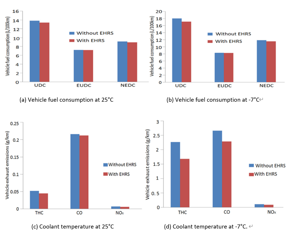
EHRS reduced fuel consumption across cold-start NEDC tests, with improvements of 2.8% in urban driving cycles (UDC) at 25°C, indicating effective mitigation of cold-start penalties through faster coolant heating and better combustion; at -7°C, UDC gains reached 4.8%, showing amplified benefits in colder conditions where extended cold soak intensifies warm-up needs. Overall NEDC improvements were 1.9% at 25°C and 2.8% at -7°C, highlighting EHRS’ transient advantages in urban cycles with frequent stops/starts versus extra-urban cycles (EUDC) with higher speeds and less warm-up sensitivity. Coolant warm-up time shortened by ~100s at 25°C and ~200s at -7°C, as shown in Fig. 11, which reduces the duration of low-efficiency combustion and directly contributes to fuel savings. Emissions also improved: THC dropped by 13.9–25.9%, attributed to alleviated combustion deterioration and wall flame quenching; CO by 1.9–13.9%, due to enhanced combustion environment despite unchanged excess air coefficient; and NOₓ by 14.3–18.2%, explained by the Fenimore mechanism where lower THC indirectly reduces NOₓ formation. EHRS effectively mitigates cold-start inefficiencies, providing a low-cost solution to meet Real Driving Emissions (RDE) regulations, with performance scaling with ambient temperature severity. The study found an overall efficiency gain of 2.8% in fuel economy under the coldest NEDC conditions.
In 2025, Jin et al. proposed a steam-injected inverted Brayton cycle (IBC) to recover both pressure energy via turbines and thermal energy via steam injection, addressing mismatches between WHR systems and engine transients [38]. The general topic of the paper is how key parameters like turbine sizing, bypass valve opening (ranging from 0% to 100%), steam injection location/ratio (0 to 0.2 mass flow ratio), and IBC power split ratio affect energy distribution and fuel economy. A 1D GT-POWER model of a D6114 turbocharged diesel engine was coupled with a steam-injected IBC simulation, as shown in Fig. 9, outputting data on exhaust energy splits, power outputs, and fuel economy improvements. The hypothesis was that optimizing turbine-steam interactions maximizes energy recuperation, improving fuel economy across engine speeds.
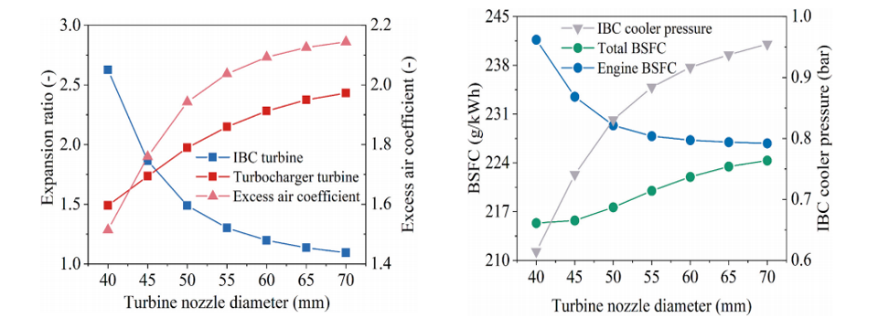
IBC turbine size dominates energy split between turbines (30%+ contribution to variance), followed by bypass valve opening, as shown in Fig. 12, indicating that larger turbines shift more energy recovery to the IBC while risking backpressure losses at low speeds. Steam injection upstream of turbochargers outperformed downstream, boosting power output by 18.7% (0.1 steam mass flow ratio increased subsystem power by 30.1%), demonstrating better thermodynamic integration and utilization of injected steam energy. At rated conditions, fuel economy improved by 7.4%, with gains scaling with speed (3.5% at rated speed, 2.8% at peak torque), highlighting high-speed favorability for WHR due to more waste heat availability. Tradeoffs include overly small IBC turbines reducing excess air ratios and worsening combustion, plus steam injection increasing exhaust backpressure that requires pump power balancing, which can lead to efficiency losses at low speeds. The steam-injected IBC system achieves cascaded waste heat reuse via parameter optimization, with turbine sizing and steam injection location being critical. The study found an overall efficiency gain of 7.4% in fuel economy at rated conditions.
5. Rankine cycle
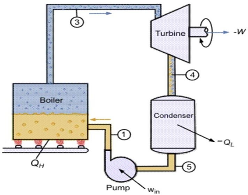
The Organic Rankine Cycle (ORC) is a closed-loop thermodynamic process designed to convert low-grade thermal energy into mechanical power. As shown in Fig. 13, it typically comprises four main components: a pump, boiler (evaporator), turbine (expander), and condenser [22]. In simple terms, the working fluid absorbs heat from the exhaust gas in the boiler, expands through the turbine to generate power, and is then cooled in the condenser before being pressurized again by the pump to complete the cycle. In automotive applications, ORC systems utilize the substantial waste heat produced by internal combustion engines during driving, thereby improving thermal efficiency and reducing fuel consumption without contravening thermodynamic principles [21]. However, challenges remain in adapting ORC to transient driving conditions, where exhaust flow and temperature fluctuate significantly, leading to reduced stability and recovery potential.
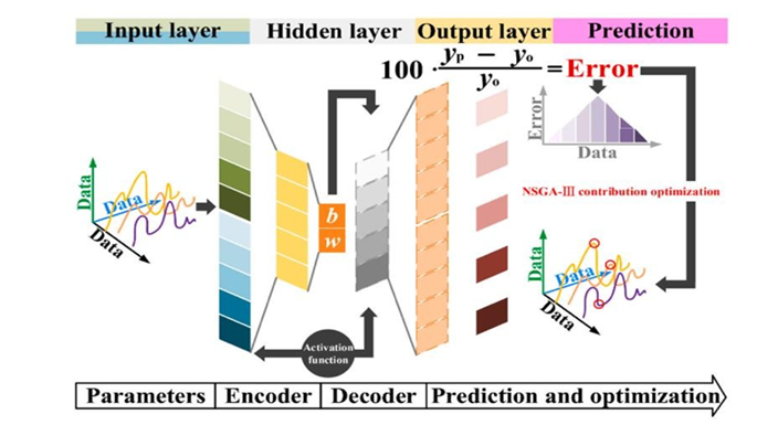
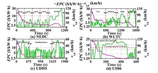
In 2023, Ping et al. systematically examined the integration of ORC systems with internal combustion engines under transient driving conditions [22]. A coupled IC engine–ORC–vehicle model was constructed in GT-Suite to represent the combined effects of the powertrain, exhaust heat recovery loop, and vehicle chassis dynamics. As shown in Fig. 14, this integrated model illustrates the heat flow from the engine exhaust to the ORC evaporator, turbine, condenser, and pump, providing a system-level view of energy transfer and recovery. Vehicle speed profiles from standardized cycles were used as inputs, while outputs included thermal efficiency, CO₂ equivalent emissions, and economic indicators such as electricity production cost. Four representative cycles were analyzed: NEDC, representing moderate-speed European driving; WLTC, characterized by longer duration and greater variability; UDDS, simulating stop-and-go low-speed urban conditions; and US06, reflecting supplemental high-speed and aggressive driving. To capture the nonlinear and strongly coupled behavior of the ORC system, a neural network–based surrogate model was trained on the simulation data to predict performance indicators under transient fluctuations. As shown in Fig. 15, this surrogate model was combined with an NSGA-III optimization framework, which systematically explored trade-offs between efficiency, economic cost, and environmental impact. Together, these methods established a comprehensive framework for evaluating ORC system adaptability and performance under realistic operating conditions.
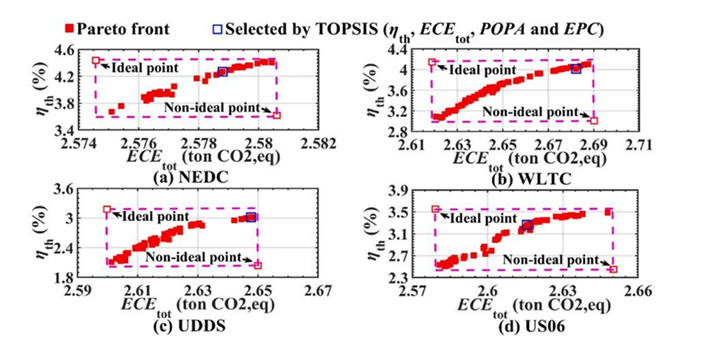
The results revealed that ORC system performance varied significantly across driving cycles, with efficiency outcomes closely tied to the stability of the exhaust heat source. Under the NEDC conditions, which combines steady acceleration and cruising phases, the system achieved a thermal efficiency limit 6.48% higher than under WLTC, demonstrating that smoother speed transitions are more favorable for stable energy recovery. In contrast, the UDDS cycle, characterized by frequent stop-and-go events, resulted in delayed thermal response and lower overall recovery efficiency compared to the high-speed US06, which outperformed UDDS by 8.31%. These differences were primarily driven by hysteresis effects in exhaust temperature and mass flow rate, which caused the ORC system to deviate from its optimal operating point during rapid transients. As shown in Fig. 16, the Electricity Production Cost (EPC) exhibited clear time delays relative to vehicle speed peaks, particularly under US06 where the hysteresis reached over 90 seconds, emphasizing the strong inertia of the system. Fig. 17 illustrates the Pareto fronts obtained from multi-objective optimization, highlighting the trade-off between improving thermal efficiency and increasing CO₂ equivalent emissions. This analysis indicates that high-speed cycles such as NEDC and US06 enable the ORC to operate closer to its efficiency limit, while urban cycles with frequent fluctuations constrain recovery potential. Overall, the study concluded that adaptive optimization strategies can achieve up to 6.48% improvement in efficiency under favorable conditions, but stability of the exhaust source remains a decisive factor in maximizing system benefits.
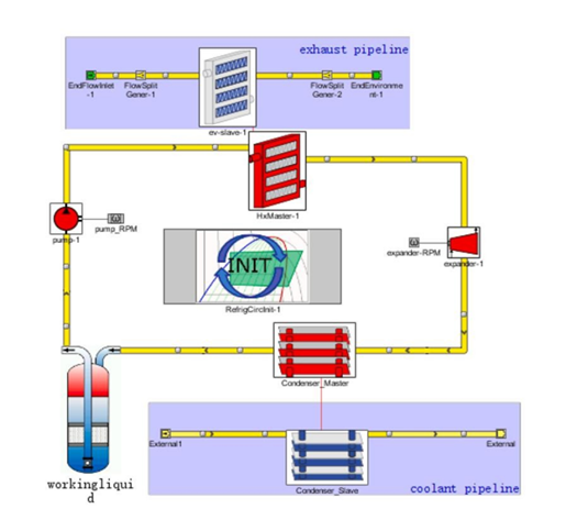
In 2020, Wang et al. systematically investigated the energy recovery efficiency of an ORC system integrated with a vehicle engine under varying driving conditions [21]. A simulation framework was developed in GT-Suite, where the internal combustion engine, ORC loop, and vehicle dynamics were coupled into a single model. As shown in Fig. 18, this integrated system captured the heat exchange path from exhaust gases to the working fluid and the subsequent power flow from the expander back to the drivetrain. The simulation used speed–time curves from representative driving cycles as inputs, while outputs included exhaust thermal availability, expander power generation, and overall recovery efficiency. Two distinct cycles were selected for comparison: the New York City Cycle (NYCC), characterized by low speeds and frequent stops typical of urban driving, and the Common Artemis Driving Cycle–motorway (CADC–motorway), representing steady high-speed highway conditions. This design allowed evaluation of ORC performance under contrasting heat source qualities, with NYCC providing a low-grade, unstable exhaust flow and CADC–motorway offering a stable, high-grade heat source. By analyzing both scenarios, the study aimed to determine how traffic patterns influence ORC adaptability and energy recovery potential.
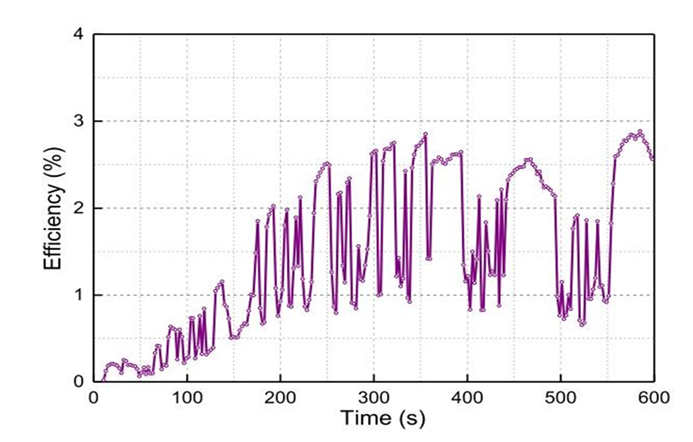
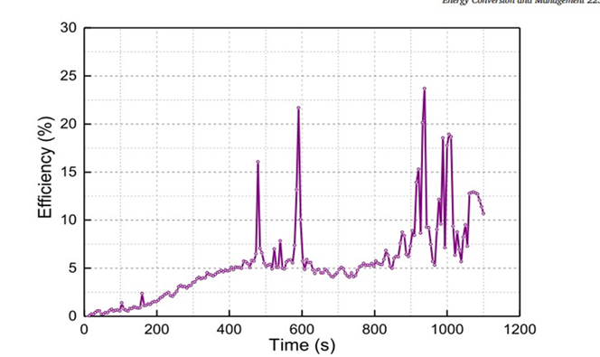
The results revealed substantial differences in ORC performance between urban and highway driving conditions. Under NYCC, frequent stops and low average speed led to unstable exhaust temperature and mass flow, producing a peak recovery efficiency of only 2.89% and a cycle average of 1.43%, as shown in Fig. 19, where the fluctuating curve indicates severe transients and limited recovery potential. In contrast, the CADC–motorway cycle provided a stable, high-grade heat source at nearly 100 km/h, allowing the ORC system to operate closer to optimal inlet conditions. This resulted in a smoother efficiency profile with a peak value of 23.7% and a cycle average of 5.50%, as shown in Fig. 20, where the curve rises steadily and maintains higher values, demonstrating effective waste heat conversion at sustained high speed. These findings indicate that the ORC system contributes more significantly to overall energy recovery and fuel efficiency improvement under steady high-speed conditions, while in urban cycles the unstable exhaust severely constrains potential gains. The study therefore highlights that the most favorable condition for improving overall vehicle efficiency is motorway operation, where the ORC system achieved an average recovery efficiency of 5.50%.
6. Electric turbochargers
As shown in Fig. 21, ETC -electric turbocharger- is an exhaust gas energy recovery system integrating an electric motor/generator directly onto the turbocharger shaft alongside the turbine and compressor. This configuration enables dual functionality. During high exhaust flow conditions (e.g. high engine load/speed), the generator converts surplus turbine rotational energy into electrical energy for storage [40]. During transient acceleration or low exhaust flow, the electric motor acts as a prime mover, providing immediate torque to eliminate "turbo lag" (which refers to the delayed response of a conventional turbocharger under low engine speed conditions, where insufficient exhaust energy causes slow turbine acceleration and delayed boost pressure buildup) and improve air delivery, significantly enhancing acceleration performance [41]. This bidirectional operation enhances engine responsiveness and recovers wasted exhaust energy.
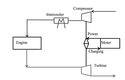
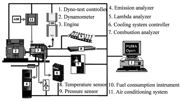
According to the first paper, in 2016, Qijun Tang et al. [40] systematically evaluated the energy-saving potential of ETC for IC engine exhaust recovery. First, they conducted some bench tests on a turbocharged gasoline engine and high-speed motor. Fig. 22 shows the schematic diagram for engine bench testing, which was first conducted on a 1.39L turbocharged gasoline engine (specifications detailed in Table 6) using an AVL dynamometer system. As shown in Table 7, the experimental setups are included. Engine parameters were measured at 200 rpm speed intervals and 1 bar BMEP (brake mean effective pressure) load intervals across the operating range to build and calibrate the simulation model. The speed, torque and power were measured using the CompactRIO real-time data acquisition system. The turbocharger is then rematched with a larger turbocharger so that all the engine working points can fall into the turbocharger map, and the pumping losses can be reduced and the engine thermal efficiency can be improved. The team then restimulated the ETC engine's working processes across the entire operating range (e.g. speeds from 1000 to 5200 r/min and loads up to full BMEP) to determine the maximum utilization efficiency of exhaust gas energy.
|
Item |
Content |
|
Engine type |
Inline four cylinder, SI engine |
|
Bore (mm) |
76.5 |
|
Stoke (mm) |
75.6 |
|
Displacement (L) |
1.39 |
|
Compression ratio |
10 |
|
Compress system |
Exhaust turbocharging |
|
Rated power |
96 kW at 5000 r/min |
|
Max torque |
210 N·m at 1750 - 3500 r/min |
|
Combustion |
Premixed combustion |
|
Equipment name |
Type |
|
Electric dynamometer |
INDY S22 - 2/0525 - IBV - 1 |
|
Dynamometer control system |
PUMA OPEN1.4.1 |
|
Fuel consumption meter |
7351 CST |
|
Data - acquisition system |
PUMA |
|
Fuel temperature control system |
753 C |
|
Coolant temperature control system |
553 CONSYSCOOL 553 - 200 |
|
Oil temperature control system |
554 CONSYSLOUBE 554 |
|
Mass air flow meter |
TP16A.00 |
|
λ analysis meter |
ETAS |
|
Burning analyzer |
INDISET ADVANCED PLUS |
|
Intake pressure sensor |
6052CS1U20 |
|
Exhaust pressure sensor |
4049A3S |
|
Intake temperature sensor |
PT100 |
|
Exhaust temperature sensor |
K Type Thermocouple |
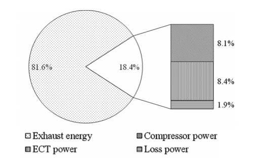
The main result is: As shown in Fig. 23, under the BMEP (brake mean effective pressure) of 15.9bar, although the turbocharger is rematched with a bigger turbine, the utilization efficiency of exhaust gas energy is still very low -the maximum value is only 18.4% which means that a large part of exhaust gas energy is still wasted and 8.4% of engine exhaust gas energy can be recovered as the ETC effective work at the speed of 5000 r/min. As for exactly how much the fuel consumption of the car can be improved, the article does not mention it. I believe this is a direction for further research in the future.
According to paper 2, in 2017, K. Ekberg et al. [41] systematically evaluated highway fuel economy, a specific driving scenario replicating a real-world 120-km Swedish highway segment (between Södertälje and Norrkoping) was implemented. This route included significant elevation changes to exploit potential energy recuperation opportunities. The truck mass was set to 40,000 kg for both test configurations (conventional and electric turbocharger). The engine model is extended with an electrical turbocharger and an electrical energy storage and you can see them in the picture, to keep track of the amount of consumed energy. A fixed-geometry turbine setting and zero exhaust gas recirculation were maintained during testing. Vehicle speed was regulated via a proportional controller adjusting fuel injection, calibrated to achieve a target mean speed of 80 km/h. A hierarchical control strategy was developed to manage power flow (uturb) between the energy storage and electric turbocharger. The primary control loop modulated power flow (uturb) proportionally to the error between measured cylinder air-to-fuel ratio (λcyl) and a reference value of 1.91 (λref = 1.91), tuned to match steady-state highway operation of the conventional truck. The strategy exploited road topography by commanding maximal exhaust energy recuperation during downhill segments.
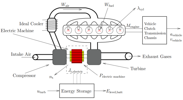
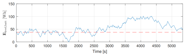
Fig. 25 shows the drive cycle data for the vehicle configuration with the electric turbocharger. It can be seen that the energy level in the battery Elevel, batt (the physical quantity represented by the vertical coordinate) is higher at the end of the cycle than in the beginning (the red dotted line represents the initial energy level in the battery), the implemented control strategy is therefore charge sustainable for the simulated case. The fuel saving potential with electric turbocharger when comparing the two different vehicle configurations is 0.9% (when comparing the relative fuel savings when 37.82 /100 km is decreased to 37.48 L/100km), highlighting their role more in enhancing engine responsiveness than in major energy recuperation.
7. Conclusion
Based on the comprehensive evaluation of five energy recovery methods, their effectiveness largely depends on driving conditions, system integration, and the recovered energy source.
• The Rankine cycle demonstrates superior theoretical efficiency, achieving a peak of 23.7% and an average of 5.50% under stable, high-load highway driving (CADC–motorway), directly converting high-quality exhaust heat into useful work.
• Regenerative braking shows high efficiency (38.8%–54.2%) in urban cycles with frequent deceleration but is markedly less effective during highway or aggressive driving where kinetic energy recovery opportunities diminish.
• Mechanical flywheels thrive in high-power, transient conditions, yielding up to 39% fuel savings in aggressive cycles, but their efficiency drops to around 20% in steady-speed scenarios like the NEDC where opportunities for energy exchange are reduced.
• Thermoelectric methods improve cold-start efficiency by up to 4.8% or provides steady-state recuperation (7.4% fuel economy improvement).
• Electric turbochargers offer ancillary benefits too, recovering only 8.4% of exhaust energy (0.9% fuel savings) while primarily enhancing engine responsiveness.
In summary, while the Rankine cycle has the highest theoretical efficiency under optimal conditions, it falters in transient low-grade heat scenarios; regenerative braking and flywheels work in urban/dynamic conditions but face constraints; thermoelectric methods and electric turbochargers offer limited energy recovery effects, and each method should be tailored to specific operational conditions.
Auhtor contribution
Jingxing Liu, Cexiao Hu, Qixuan Qiu, Junyi Kang and Xuetianfu Peng contributed equally to this work and should be considered co-first authors.
References
[1]. A. T. Hamada and M. F. Orhan, “An overview of regenerative braking systems, ” J. Energy Storage, vol. 52, p. 105033, Aug. 2022, doi: 10.1016/j.est.2022.105033.
[2]. --“EU-DG-TREN, EU energy in figures 2010, CO2 Emissions by Sector, European Commission directorate general for energy and transport, ” 2010.
[3]. A. Gabriel-Buenaventura and B. Azzopardi, “Energy recovery systems for retrofitting in internal combustion engine vehicles: A review of techniques, ” Renew. Sustain. Energy Rev., vol. 41, pp. 955–964, Jan. 2015, doi: 10.1016/j.rser.2014.08.083.
[4]. A. J. Stratton and J. B. Heywood, “Impact of regenerative braking on hybrid vehicle fuel economy”.
[5]. --“The Oerlikon electrogyro—Its development and application for omnibus service, ” Autom Eng, no. 45, pp. 559–566, 1955.
[6]. --“Gyrobus: A Great Idea Takes a Spin, ” June 09, 2015. [Online]. Available: http: //photo.proaktiva.eu/digest/2008_g yrobus.html
[7]. B. Bolund, H. Bernhoff, and M. Leijon, “Flywheel energy and power storage systems, ” Renew. Sustain. Energy Rev., vol. 11, no. 2, pp. 235–258, Feb. 2007, doi: 10.1016/j.rser.2005.01.004.
[8]. Talreja, & R. “Fatigue of composite materials: damage mechanisms and fatigue-life diagrams, ” Proc. R. Soc. Lond. Math. Phys. Sci., vol. 378, no. 1775, pp. 461–475, Nov. 1981, doi: 10.1098/rspa.1981.0163.
[9]. --“Faurecia partners with CEA on stack R& D, ” Fuel Cells Bull., vol. 2017, Issue 11, pp. 11–12, 2017, doi: 10.1016/S1464-2859(17)30394-2.
[10]. M. A. Abdelkareem et al., “Heat pipe-based waste heat recovery systems: Background and applications, ” Therm. Sci. Eng. Prog., vol. 29, p. 101221, Mar. 2022, doi: 10.1016/j.tsep.2022.101221.
[11]. F. Fatigati, D. Di Battista, and R. Carapellucci, “Model-based assessment of a feedforward-feedback control strategy for ORC-based unit in waste heat recovery application, ” Appl. Therm. Eng., vol. 258, p. 124774, Jan. 2025, doi: 10.1016/j.applthermaleng.2024.124774.
[12]. A. Marvão, P. J. Coelho, and H. C. Rodrigues, “Optimization of a thermoelectric generator for heavy-duty vehicles, ” Energy Convers. Manag., vol. 179, pp. 178–191, Jan. 2019, doi: 10.1016/j.enconman.2018.10.045.
[13]. X. Ping et al., “Prediction and optimization of power output of single screw expander in organic Rankine cycle (ORC) for diesel engine waste heat recovery, ” Appl. Therm. Eng., vol. 182, p. 116048, Jan. 2021, doi: 10.1016/j.applthermaleng.2020.116048.
[14]. K. Shen, L. Chang, H. Chen, Z. Zhang, B. Wang, and Y. Wang, “Experimental study on the effects of exhaust heat recovery system (EHRS) on vehicle fuel economy and emissions under cold start new European driving cycle (NEDC), ” Energy Convers. Manag., vol. 197, p. 111893, Oct. 2019, doi: 10.1016/j.enconman.2019.111893.
[15]. S. Yu, Q. Du, H. Diao, G. Shu, and K. Jiao, “Effect of vehicle driving conditions on the performance of thermoelectric generator, ” Energy Convers. Manag., vol. 96, pp. 363–376, May 2015, doi: 10.1016/j.enconman.2015.03.002.
[16]. L. Shi, G. Shu, H. Tian, and S. Deng, “A review of modified Organic Rankine cycles (ORCs) for internal combustion engine waste heat recovery (ICE-WHR), ” Renew. Sustain. Energy Rev., vol. 92, pp. 95–110, Sept. 2018, doi: 10.1016/j.rser.2018.04.023.
[17]. F. Zhou, S. N. Joshi, R. Rhote-Vaney, and E. M. Dede, “A review and future application of Rankine Cycle to passenger vehicles for waste heat recovery, ” Renew. Sustain. Energy Rev., vol. 75, pp. 1008–1021, Aug. 2017, doi: 10.1016/j.rser.2016.11.080.
[18]. O. Nett and A. Salomon, “Experimental analysis of engine out emissions of a light-duty diesel engine during warm-up under cold start conditions, ” Transp. Eng., vol. 10, p. 100128, Dec. 2022, doi: 10.1016/j.treng.2022.100128.
[19]. M. Moses-DeBusk et al., “Detailed hydrocarbon speciation and particulate matter emissions during cold-start from turbocharged and naturally aspirated trucks, ” Fuel, vol. 350, p. 128804, Oct. 2023, doi: 10.1016/j.fuel.2023.128804.
[20]. X. Duan, J. Fu, Z. Zhang, J. Liu, D. Zhao, and G. Zhu, “Experimental study on the energy flow of a gasoline-powered vehicle under the NEDC of cold starting, ” Appl. Therm. Eng., vol. 115, pp. 1173–1186, Mar. 2017, doi: 10.1016/j.applthermaleng.2016.10.002.
[21]. C. Wang, F. Yang, H. Zhang, R. Zhao, and Y. Xu, “Energy recovery efficiency analysis of organic Rankine cycle system in vehicle engine under different road conditions, ” Energy Convers. Manag., vol. 223, p. 113317, Nov. 2020, doi: 10.1016/j.enconman.2020.113317.
[22]. X. Ping et al., “Dynamic response assessment and multi-objective optimization of organic Rankine cycle (ORC) under vehicle driving cycle conditions, ” Energy, vol. 263, p. 125551, Jan. 2023, doi: 10.1016/j.energy.2022.125551.
[23]. Hopmann, U., & Algrain, M. C., “Diesel engine electric turbo compound technology, ” SAE Tech. Pap., no. 2003-01–2294, 2003.
[24]. Ibaraki, S., Yamashita, Y., Sumida, K., Ogita, H., & Jinnai, Y., “Development of the hybrid turbo, an electrically assisted turbocharger, ” 2006.
[25]. Kattwinkel, T., Weiss, R., and Boeschlin, J., “Mechatronic Solution for Electronic Turbocharger, ” SAE Tech. Pap., no. 2003-01–0712, p. 200, 2003.
[26]. P. S. Divekar, B. Ayalew, and R. Prucka, “Coordinated Electric Supercharging and Turbo-Generation for a Diesel Engine, ” presented at the SAE 2010 World Congress & Exhibition, Apr. 2010, pp. 2010-01–1228. doi: 10.4271/2010-01-1228.
[27]. Arsie, I., Cricchio, A., Pianese, C., De Cesare, M., & Nesci, W., “A comprehensive powertrain model to evaluate the benefits of electric turbo compound (ETC) in reducing CO2 emissions from small diesel passenger cars, ” SAE Tech. Pap., no. 2014-01–1650, 2014.
[28]. J. Ko, S. Ko, H. Son, B. Yoo, J. Cheon, and H. Kim, “Development of Brake System and Regenerative Braking Cooperative Control Algorithm for Automatic-Transmission-Based Hybrid Electric Vehicles, ” IEEE Trans. Veh. Technol., vol. 64, no. 2, pp. 431–440, Feb. 2015, doi: 10.1109/tvt.2014.2325056.
[29]. Z. Meng, T. Zhang, H. Zhang, Q. Zhao, and J. Yang, “Energy Management Strategy for an Electromechanical-Hydraulic Coupled Power Electric Vehicle Considering the Optimal Speed Threshold, ” Energies, vol. 14, no. 17, p. 5300, Aug. 2021, doi: 10.3390/en14175300.
[30]. E. Pipitone and G. Vitale, “A regenerative braking system for internal combustion engine vehicles using supercapacitors as energy storage elements - Part 2: Simulation results, ” J. Power Sources, vol. 448, p. 227258, Feb. 2020, doi: 10.1016/j.jpowsour.2019.227258.
[31]. S. B. Chaganti and B. Chaganti, “KAMMA Gear Flywheel Hybrid Perpetual Mechanical Battery, ” in 2023 9th IEEE India International Conference on Power Electronics (IICPE), SONIPAT, India: IEEE, Nov. 2023, pp. 1–4. doi: 10.1109/IICPE60303.2023.10474946.
[32]. A. A. K. Arani, H. Karami, G. B. Gharehpetian, and M. S. A. Hejazi, “Review of Flywheel Energy Storage Systems structures and applications in power systems and microgrids, ” Renew. Sustain. Energy Rev., vol. 69, pp. 9–18, Mar. 2017, doi: 10.1016/j.rser.2016.11.166.
[33]. A. Dhand and K. Pullen, “Review of flywheel based internal combustion engine hybrid vehicles, ” Int. J. Automot. Technol., vol. 14, no. 5, pp. 797–804, Oct. 2013, doi: 10.1007/s12239-013-0088-x.
[34]. M. Hedlund, J. Lundin, J. De Santiago, J. Abrahamsson, and H. Bernhoff, “Flywheel Energy Storage for Automotive Applications, ” Energies, vol. 8, no. 10, pp. 10636–10663, Oct. 2015, doi: 10.3390/en81010636.
[35]. J. Hilton, “Flybrid systems—Mechanical hybrid systems, ” presented at the Proceedings of the Engine Expo 2008, Stuttgart, Germany, May 06, 2008.
[36]. I. Foley, “Williams Hybrid Power—Flywheel Energy Storage, ” presented at the Presentation, 2013. [Online]. Available: http: //www.ukintpress-conferences.com/uploads/SPKPMW13R/d1_s1_p2_ian_foley.pdf
[37]. K. Van Berkel, T. Hofman, B. Vroemen, and M. Steinbuch, “Optimal energy management for a flywheel-based hybrid vehicle, ” in Proceedings of the 2011 American Control Conference, San Francisco, CA: IEEE, June 2011, pp. 5255–5260. doi: 10.1109/ACC.2011.5990820.
[38]. B. Jin et al., “Parametric study on a novel steam injected inverted Brayton cycle system recovering waste heat from the internal combustion engine, ” Appl. Therm. Eng., vol. 274, p. 126774, Sept. 2025, doi: 10.1016/j.applthermaleng.2025.126774.
[39]. M. M. Zia et al., “Analysis of Rankine Heat Engine Cycle and Optimization of Cycle Efficiency Between Maximum and Minimum Working Pressures, ” 2024, doi: 10.13140/RG.2.2.32676.69764.
[40]. Q. Tang, J. Fu, J. Liu, F. Zhou, and X. Duan, “Study of Energy-Saving Potential of Electronically Controlled Turbocharger for Internal Combustion Engine Exhaust Gas Energy Recovery, ” J. Eng. Gas Turbines Power, vol. 138, no. 11, Nov. 2016, doi: 10.1115/1.4033535.
[41]. K. Ekberg and L. Eriksson, “Improving Fuel Economy and Acceleration by Electric Turbocharger Control for Heavy Duty Long Haulage, ” IFAC-Pap., vol. 50, no. 1, pp. 11052–11057, July 2017, doi: 10.1016/j.ifacol.2017.08.2486.
Cite this article
Liu,J.;Hu,C.;Qiu,Q.;Kang,J.;Peng,X. (2025). Comparative Evaluation of Energy Recovery Systems for Enhanced Automotive Overall Efficiency. Applied and Computational Engineering,188,83-107.
Data availability
The datasets used and/or analyzed during the current study will be available from the authors upon reasonable request.
Disclaimer/Publisher's Note
The statements, opinions and data contained in all publications are solely those of the individual author(s) and contributor(s) and not of EWA Publishing and/or the editor(s). EWA Publishing and/or the editor(s) disclaim responsibility for any injury to people or property resulting from any ideas, methods, instructions or products referred to in the content.
About volume
Volume title: Proceedings of CONF-MCEE 2026 Symposium: Advances in Sustainable Aviation and Aerospace Vehicle Automation
© 2024 by the author(s). Licensee EWA Publishing, Oxford, UK. This article is an open access article distributed under the terms and
conditions of the Creative Commons Attribution (CC BY) license. Authors who
publish this series agree to the following terms:
1. Authors retain copyright and grant the series right of first publication with the work simultaneously licensed under a Creative Commons
Attribution License that allows others to share the work with an acknowledgment of the work's authorship and initial publication in this
series.
2. Authors are able to enter into separate, additional contractual arrangements for the non-exclusive distribution of the series's published
version of the work (e.g., post it to an institutional repository or publish it in a book), with an acknowledgment of its initial
publication in this series.
3. Authors are permitted and encouraged to post their work online (e.g., in institutional repositories or on their website) prior to and
during the submission process, as it can lead to productive exchanges, as well as earlier and greater citation of published work (See
Open access policy for details).
References
[1]. A. T. Hamada and M. F. Orhan, “An overview of regenerative braking systems, ” J. Energy Storage, vol. 52, p. 105033, Aug. 2022, doi: 10.1016/j.est.2022.105033.
[2]. --“EU-DG-TREN, EU energy in figures 2010, CO2 Emissions by Sector, European Commission directorate general for energy and transport, ” 2010.
[3]. A. Gabriel-Buenaventura and B. Azzopardi, “Energy recovery systems for retrofitting in internal combustion engine vehicles: A review of techniques, ” Renew. Sustain. Energy Rev., vol. 41, pp. 955–964, Jan. 2015, doi: 10.1016/j.rser.2014.08.083.
[4]. A. J. Stratton and J. B. Heywood, “Impact of regenerative braking on hybrid vehicle fuel economy”.
[5]. --“The Oerlikon electrogyro—Its development and application for omnibus service, ” Autom Eng, no. 45, pp. 559–566, 1955.
[6]. --“Gyrobus: A Great Idea Takes a Spin, ” June 09, 2015. [Online]. Available: http: //photo.proaktiva.eu/digest/2008_g yrobus.html
[7]. B. Bolund, H. Bernhoff, and M. Leijon, “Flywheel energy and power storage systems, ” Renew. Sustain. Energy Rev., vol. 11, no. 2, pp. 235–258, Feb. 2007, doi: 10.1016/j.rser.2005.01.004.
[8]. Talreja, & R. “Fatigue of composite materials: damage mechanisms and fatigue-life diagrams, ” Proc. R. Soc. Lond. Math. Phys. Sci., vol. 378, no. 1775, pp. 461–475, Nov. 1981, doi: 10.1098/rspa.1981.0163.
[9]. --“Faurecia partners with CEA on stack R& D, ” Fuel Cells Bull., vol. 2017, Issue 11, pp. 11–12, 2017, doi: 10.1016/S1464-2859(17)30394-2.
[10]. M. A. Abdelkareem et al., “Heat pipe-based waste heat recovery systems: Background and applications, ” Therm. Sci. Eng. Prog., vol. 29, p. 101221, Mar. 2022, doi: 10.1016/j.tsep.2022.101221.
[11]. F. Fatigati, D. Di Battista, and R. Carapellucci, “Model-based assessment of a feedforward-feedback control strategy for ORC-based unit in waste heat recovery application, ” Appl. Therm. Eng., vol. 258, p. 124774, Jan. 2025, doi: 10.1016/j.applthermaleng.2024.124774.
[12]. A. Marvão, P. J. Coelho, and H. C. Rodrigues, “Optimization of a thermoelectric generator for heavy-duty vehicles, ” Energy Convers. Manag., vol. 179, pp. 178–191, Jan. 2019, doi: 10.1016/j.enconman.2018.10.045.
[13]. X. Ping et al., “Prediction and optimization of power output of single screw expander in organic Rankine cycle (ORC) for diesel engine waste heat recovery, ” Appl. Therm. Eng., vol. 182, p. 116048, Jan. 2021, doi: 10.1016/j.applthermaleng.2020.116048.
[14]. K. Shen, L. Chang, H. Chen, Z. Zhang, B. Wang, and Y. Wang, “Experimental study on the effects of exhaust heat recovery system (EHRS) on vehicle fuel economy and emissions under cold start new European driving cycle (NEDC), ” Energy Convers. Manag., vol. 197, p. 111893, Oct. 2019, doi: 10.1016/j.enconman.2019.111893.
[15]. S. Yu, Q. Du, H. Diao, G. Shu, and K. Jiao, “Effect of vehicle driving conditions on the performance of thermoelectric generator, ” Energy Convers. Manag., vol. 96, pp. 363–376, May 2015, doi: 10.1016/j.enconman.2015.03.002.
[16]. L. Shi, G. Shu, H. Tian, and S. Deng, “A review of modified Organic Rankine cycles (ORCs) for internal combustion engine waste heat recovery (ICE-WHR), ” Renew. Sustain. Energy Rev., vol. 92, pp. 95–110, Sept. 2018, doi: 10.1016/j.rser.2018.04.023.
[17]. F. Zhou, S. N. Joshi, R. Rhote-Vaney, and E. M. Dede, “A review and future application of Rankine Cycle to passenger vehicles for waste heat recovery, ” Renew. Sustain. Energy Rev., vol. 75, pp. 1008–1021, Aug. 2017, doi: 10.1016/j.rser.2016.11.080.
[18]. O. Nett and A. Salomon, “Experimental analysis of engine out emissions of a light-duty diesel engine during warm-up under cold start conditions, ” Transp. Eng., vol. 10, p. 100128, Dec. 2022, doi: 10.1016/j.treng.2022.100128.
[19]. M. Moses-DeBusk et al., “Detailed hydrocarbon speciation and particulate matter emissions during cold-start from turbocharged and naturally aspirated trucks, ” Fuel, vol. 350, p. 128804, Oct. 2023, doi: 10.1016/j.fuel.2023.128804.
[20]. X. Duan, J. Fu, Z. Zhang, J. Liu, D. Zhao, and G. Zhu, “Experimental study on the energy flow of a gasoline-powered vehicle under the NEDC of cold starting, ” Appl. Therm. Eng., vol. 115, pp. 1173–1186, Mar. 2017, doi: 10.1016/j.applthermaleng.2016.10.002.
[21]. C. Wang, F. Yang, H. Zhang, R. Zhao, and Y. Xu, “Energy recovery efficiency analysis of organic Rankine cycle system in vehicle engine under different road conditions, ” Energy Convers. Manag., vol. 223, p. 113317, Nov. 2020, doi: 10.1016/j.enconman.2020.113317.
[22]. X. Ping et al., “Dynamic response assessment and multi-objective optimization of organic Rankine cycle (ORC) under vehicle driving cycle conditions, ” Energy, vol. 263, p. 125551, Jan. 2023, doi: 10.1016/j.energy.2022.125551.
[23]. Hopmann, U., & Algrain, M. C., “Diesel engine electric turbo compound technology, ” SAE Tech. Pap., no. 2003-01–2294, 2003.
[24]. Ibaraki, S., Yamashita, Y., Sumida, K., Ogita, H., & Jinnai, Y., “Development of the hybrid turbo, an electrically assisted turbocharger, ” 2006.
[25]. Kattwinkel, T., Weiss, R., and Boeschlin, J., “Mechatronic Solution for Electronic Turbocharger, ” SAE Tech. Pap., no. 2003-01–0712, p. 200, 2003.
[26]. P. S. Divekar, B. Ayalew, and R. Prucka, “Coordinated Electric Supercharging and Turbo-Generation for a Diesel Engine, ” presented at the SAE 2010 World Congress & Exhibition, Apr. 2010, pp. 2010-01–1228. doi: 10.4271/2010-01-1228.
[27]. Arsie, I., Cricchio, A., Pianese, C., De Cesare, M., & Nesci, W., “A comprehensive powertrain model to evaluate the benefits of electric turbo compound (ETC) in reducing CO2 emissions from small diesel passenger cars, ” SAE Tech. Pap., no. 2014-01–1650, 2014.
[28]. J. Ko, S. Ko, H. Son, B. Yoo, J. Cheon, and H. Kim, “Development of Brake System and Regenerative Braking Cooperative Control Algorithm for Automatic-Transmission-Based Hybrid Electric Vehicles, ” IEEE Trans. Veh. Technol., vol. 64, no. 2, pp. 431–440, Feb. 2015, doi: 10.1109/tvt.2014.2325056.
[29]. Z. Meng, T. Zhang, H. Zhang, Q. Zhao, and J. Yang, “Energy Management Strategy for an Electromechanical-Hydraulic Coupled Power Electric Vehicle Considering the Optimal Speed Threshold, ” Energies, vol. 14, no. 17, p. 5300, Aug. 2021, doi: 10.3390/en14175300.
[30]. E. Pipitone and G. Vitale, “A regenerative braking system for internal combustion engine vehicles using supercapacitors as energy storage elements - Part 2: Simulation results, ” J. Power Sources, vol. 448, p. 227258, Feb. 2020, doi: 10.1016/j.jpowsour.2019.227258.
[31]. S. B. Chaganti and B. Chaganti, “KAMMA Gear Flywheel Hybrid Perpetual Mechanical Battery, ” in 2023 9th IEEE India International Conference on Power Electronics (IICPE), SONIPAT, India: IEEE, Nov. 2023, pp. 1–4. doi: 10.1109/IICPE60303.2023.10474946.
[32]. A. A. K. Arani, H. Karami, G. B. Gharehpetian, and M. S. A. Hejazi, “Review of Flywheel Energy Storage Systems structures and applications in power systems and microgrids, ” Renew. Sustain. Energy Rev., vol. 69, pp. 9–18, Mar. 2017, doi: 10.1016/j.rser.2016.11.166.
[33]. A. Dhand and K. Pullen, “Review of flywheel based internal combustion engine hybrid vehicles, ” Int. J. Automot. Technol., vol. 14, no. 5, pp. 797–804, Oct. 2013, doi: 10.1007/s12239-013-0088-x.
[34]. M. Hedlund, J. Lundin, J. De Santiago, J. Abrahamsson, and H. Bernhoff, “Flywheel Energy Storage for Automotive Applications, ” Energies, vol. 8, no. 10, pp. 10636–10663, Oct. 2015, doi: 10.3390/en81010636.
[35]. J. Hilton, “Flybrid systems—Mechanical hybrid systems, ” presented at the Proceedings of the Engine Expo 2008, Stuttgart, Germany, May 06, 2008.
[36]. I. Foley, “Williams Hybrid Power—Flywheel Energy Storage, ” presented at the Presentation, 2013. [Online]. Available: http: //www.ukintpress-conferences.com/uploads/SPKPMW13R/d1_s1_p2_ian_foley.pdf
[37]. K. Van Berkel, T. Hofman, B. Vroemen, and M. Steinbuch, “Optimal energy management for a flywheel-based hybrid vehicle, ” in Proceedings of the 2011 American Control Conference, San Francisco, CA: IEEE, June 2011, pp. 5255–5260. doi: 10.1109/ACC.2011.5990820.
[38]. B. Jin et al., “Parametric study on a novel steam injected inverted Brayton cycle system recovering waste heat from the internal combustion engine, ” Appl. Therm. Eng., vol. 274, p. 126774, Sept. 2025, doi: 10.1016/j.applthermaleng.2025.126774.
[39]. M. M. Zia et al., “Analysis of Rankine Heat Engine Cycle and Optimization of Cycle Efficiency Between Maximum and Minimum Working Pressures, ” 2024, doi: 10.13140/RG.2.2.32676.69764.
[40]. Q. Tang, J. Fu, J. Liu, F. Zhou, and X. Duan, “Study of Energy-Saving Potential of Electronically Controlled Turbocharger for Internal Combustion Engine Exhaust Gas Energy Recovery, ” J. Eng. Gas Turbines Power, vol. 138, no. 11, Nov. 2016, doi: 10.1115/1.4033535.
[41]. K. Ekberg and L. Eriksson, “Improving Fuel Economy and Acceleration by Electric Turbocharger Control for Heavy Duty Long Haulage, ” IFAC-Pap., vol. 50, no. 1, pp. 11052–11057, July 2017, doi: 10.1016/j.ifacol.2017.08.2486.