


1. Introduction
High-altitude hazardous weather phenomena is aircraft ice accumulation, which is the situation where an aircraft flies in a cloud rain layer with supercooled water droplets and when the surface temperature of the fuselage is below 0 °C, ice forms in specific areas of the fuselage [1]. When an airplane is flying in a cloud or precipitation area, it is mostly created by supercooled cloud droplets in the cloud or raindrops in the precipitation process, which then freeze after hitting with the fuselage. It can also be created directly by water vapor condensation on the fuselage's surface. The sort of ice that formed on the aircraft during actual flight varied depending on the distinct physical mechanisms of ice buildup. The influence on the aircraft will also vary in intensity. According to extensive observation, the three basic varieties of ice are Rime ice, Glaze ice, and mixed ice [2]. Pneumatic anti-deicing covers, liquid anti-icing, electro-thermal anti-deicing technology, and gas-thermal anti-deicing technology are the primary anti-icing technologies used on modern airplanes. This paper takes the first half of the method of categorization and aggregation, and then compares and analyzes each ice type for each anti-icing method, and uses the data to compare the advantages and disadvantages. This research can greatly reduce the anti-icing resources and design space required by the aircraft in winter, and at the same time allow the aircraft to maintain its aerodynamic configuration to the greatest extent when it freezes, so it is important that we understand and take steps to avoid it.
2. Aircraft icing types
2.1. Rime ice
Small supercooled water droplets that come into touch with a subzero surface quickly freeze, forming rime ice. Because the droplets are small, the shift to a frozen state happens quickly, and the practically instantaneous change creates a combination of minute ice particles and trapped air [2]. The resulting ice deposit is fragile due to its crystalline structure, rough, crystalline, and opaque. When seen from a distance, such as from the flight deck when it is on a wing leading edge, it appears white in color. Rime ice may impair the aerodynamic properties of both wings and horizontal stabilizers as well as limiting engine air inlets since it develops on leading edges. Although there are structural limits to how much "horn" growth is possible, rime may start to form as a rough covering on a leading edge, and if accretion continues, irregular protrusions may develop forward into the airstream.
2.2. Clear ice
Larger supercooled water droplets, of which only a tiny percentage instantly freezes, combine to produce clear or glazed ice. Due to the reflux and slow freezing of the remaining liquid as a result, the ice that has collected is clear or translucent and includes only a small number of air bubbles [2]. Transparent ice flakes may be challenging to spot if the freezing process is slow enough to allow the water to spread more evenly before freezing. The ice will be more transparent the larger the droplet and the slower the freezing process.
A "double plunger corner" configuration with protrusions on both the upper and lower leading edge surfaces can occasionally be seen in front of the leading edge depending on the temperature and droplet size [3]. Since transparent ice has a stronger structure than frost ice, these horns have been shown to appear in a variety of shapes and sizes over a wide range of places on the leading edge.
2.3. Mixed ice
It is most typical for a mixture of these two types of accumulated ice to occur, which can be either predominantly rime or mostly clear/glazed. The degree to which it is composed of water droplets of varying sizes that have been supercooled will determine how it looks. These three types of ices are shown in figure 1.
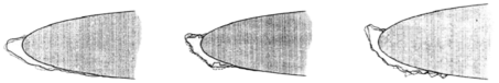
a. Rime ice b. Clear ice c. Mixed ice
Figure 1. Ice types [2].
2.4. SLD
A droplet greater than 50 microns in diameter is referred to as a supercooled large droplet (SLD) if its bulk prevents pressure waves that are moving in front of the wing pattern from deflecting it. When this occurs, the droplet will go considerably farther than a typical cloud-sized droplet and may even pass outside the zone of protection, where it may turn into clear ice. This size of the droplet is frequently observed in regions of freezing rain and freezing monsoon rain. Large droplets are indications of probable in-flight icing as well as updrafts and wind shear, which are both detected by weather radar [3].
3. Effects of aircraft icing
3.1. Characteristics of operational stability as a result of aircraft icing
Horizontal tail ice buildup can seriously affect the maneuvering efficiency of the aircraft, and in order to maintain longitudinal. In order to maintain longitudinal balance, a larger elevator angle is required, which will also lead to additional. This will also lead to additional low-head moment and a smaller critical angle of approach, which is detrimental to flight safety. If aircraft icing occurs in the gap area of the maneuvering surface. If aircraft icing occurs in the gap area of the maneuvering surface, the rudder surface may become jammed [4]. In severe ice accumulation, the aircraft will lose maneuverability. In addition, due to that, the aircraft's mass distribution and aerodynamic profile will change, and the center of gravity and wing. The longitudinal and lateral aerodynamic derivatives of the aircraft will change accordingly, affecting the stability of the aircraft. The longitudinal and lateral aerodynamic derivatives of the aircraft will be changed, which will affect the stability and response characteristics of the aircraft.
3.2. Effect of ice accumulation on aerodynamic characteristics
Damage to the aerodynamic profile is the principal consequence of icing for airplanes. The early turning of the boundary layer and early airflow separation that might result from roughness creation can lower the critical angle of approach [5]. In addition, when the flow field changes, the airfoil's lift and drag characteristics significantly deteriorate, with increased drag, decreased lift, higher stall speed, changed pitch moment, and decreased stability. For instance, ice accumulation on the surface of the airfoil might interfere with the smooth flow line that surrounds it, causing the airflow to split too soon and lowering the lift-to-drag ratio as a result. The lift and drag coefficients of the airfoil before and after ice accumulation at various ambient temperatures are shown in Table 1. The lift coefficient reduces and the drag coefficient rises as a result of the ice formation, which is bad for flight safety, according to the data in the table.
Table 1. Data of different air stages [2].
Aircraft take-off parameters | Iced | Non-iced | Percentage |
Ground clearance speed | 66.04 | 69.1 | 4. 63% |
Takeoff ground glide distance | 464.7 | 505. 8 | 8. 84% |
Takeoff air segment distance | 122.5 | 145. 2 | 18. 53% |
Take-off distance | 655. 3 | 719. 3 | 9.77% |
Takeoff glide distance | 604. 9 | 665. 2 | 9.97% |
3.3. Effect of ice accumulation on takeoff and landing performance
When an aircraft experiences ice accumulation during takeoff, the decreased aerodynamic performance will cause the lift characteristics to drop and the weight of the airframe to increase, which will cause the original takeoff speed to no longer be possible. The takeoff speed must be raised since the initial takeoff speed will no longer be suitable for takeoff. During the takeoff, when the angle of approach increases and the aircraft speed is too low during the takeoff phase, it will quickly stall. Due to ice formation during the landing phase, the properties of lift resistance change, resulting in a difference between approach speed and ground speed [6]. The airplane needs a larger braking distance and braking speed in order to land safely. The airplane needs a larger braking distance and braking time in order to land safely. Additionally, the ice accumulation reduces the effectiveness of flat tail handling. The ice will make flat-tail handling less effective, increasing the degree of pilot operation needed. If the pilot is not careful, an accident is likely to occur. According to statistics, the takeoff phase accounts for about 1/3 of the flight accidents caused by icing. The takeoff phase accounts for about 1/3 of the flight accidents caused by icing.
4. Anti-icing technology
4.1. Pneumatic removal shield technology
An inflated rubber de-icing bag will be installed on the leading edge of the airfoil using the pneumatic anti-icing shield technology. People can position the expansion tube in the chord's direction. When de-icing is necessary, the expansion tube of the de-icing tape is inflated with air at a certain pressure, which breaks up the ice [7]. The vacuum system creates a vacuum when not de-icing to keep the tape near the airfoil to preserve a nice aerodynamic look. It is primarily mounted to the leading edge of the wing, the leading edge of the drogue, the flat tail, the heater and engine intake, the flight operating surface, the piston engine vaporizer, and the aircraft. vaporizing tubes in piston engines and flight operational surfaces. Pneumatic de-icing has the benefits of energy efficiency and dependable operation.
There are several problems with pneumatic deicing hood technology. Deicing hoods must be updated periodically because air leakage caused by any flaws in the hood's surface might render it useless for deicing. Before takeoff, ground staff must thoroughly inspect their integrity. When an aircraft is flying at a high altitude and heavy ice accumulation occurs, the rate of ice accumulation is likely to be much higher than the rate at which the pneumatic deicing cover devices, and during the deicing process, more complex ice patterns are likely to form, which will negatively impact the aircraft's aerodynamic performance [8]. Pneumatic deicing technique currently has a limited range of applications and is mostly employed in wings and tails. Because it is difficult to entirely remove the ice from the airframe's surface due to the deicing cover, there will always be some residual ice, which raises the drag. Therefore, general-purpose or medium-sized aircraft are the only ones that utilize pneumatic deicing shroud technology. At temperatures below -40°C, it has been discovered that this technique is ineffective and tends to harm the tape. Additionally, the pneumatic deicing technique has trouble working when the ice thickness on the wing region is less than 9.5 mm.
4.2. Liquid anti-icing technology
The idea behind liquid anti-icing is to combine supercooled water droplets with a liquid that has a very low freezing point, then spray the combination on the area where ice is accumulating to stop it from icing. A storage tank, pump, filter, controller, pipeline, and liquid dispenser are typical components of a technological system [7]. The liquid distributor uniformly distributes the anti-icing solutions to the component's surface as the pump exerts pressure. At the moment, ethylene glycol, ethanol, and other substances can be utilized as anti-icing solution. The windshield, glass, radomes, leading edges of propeller blades, and piston engine carburetors are the principal targets of the anti-icing fluid's action.
The technique behind liquid anti-icing has a lot of disadvantages as well. Some anti-icing solutions include a lot of organic materials, some of which are hazardous, and releasing a lot of them might be bad for the ecosystem around the airport. This technique has been proven to have poor de-icing performance, a brief window of effectiveness, and a high anti-icing fluid need. As a result, during the colder months, it is mostly utilized for ground anti-icing prior to aircraft takeoff.
4.3. Electrical-thermal technology
The electro-thermal anti-icing method dissolves ice by heating the surface of the component by converting electrical energy into heat. A power source, a selector switch, an overheating prevention mechanism, and a heating element typically make up an electric anti-icing system. The surface of the component is heated by the electric heating element in order to avoid deicing [7]. This is done by converting the electrical energy from the electrical energy source into heat energy. The overheating protection device is used to stop overheating and deformation of the body's surface skin. The stall warning sensor, pilot tube, propeller, and leading edge of the propeller are the major components of the electric heating anti-deicing system.
But there are disadvantages to this technology, which is employed in current airplanes. The electro-thermal approach is cumbersome and complex in comparison to a number of other anti-icing technologies, which is a considerable burden for airplanes with extremely limited capacity. While stainless steel foil makes up the majority of the heating components used in electro-thermal anti-icing systems, these systems still have drawbacks, such as low electro-thermal conversion efficiency, slow heating rates, the requirement for large amounts of power, and thermal inertia. What's worse is that secondary icing, which is simple to develop tumor ice and has a significant influence on flight performance, will result from the melting of the already-generated ice after the electro-thermal anti-icing system is activated. The effectiveness of the flight will be greatly impacted by this.
4.4. Aerothermal anti-icing technology
In order to avoid icing, contemporary aircraft's airfoil is mostly heated with hot air. The engine pressurizer, auxiliary power unit (APU), or, in certain aircraft, a waste heater or combustion heater, are the main sources of the anti-icing hot air [7]. The heated throttle and heat source valve are opened by the electric gate turn-on motor, allowing warm air to enter the anti-icing channel. The pressure regulator regulates and the temperature sensor detects the heated anti-ice air. When the temperature sensor enters the anti-ice pipe in the anti-ice chamber of the wing and trailing edge after sensing the temperature, hot air at a certain pressure is released.
However, this technology is not yet perfect, and the pilot air of the aircraft’s aerothermal anti-icing system will have an impact on the operational performance of the aircraft, and even excessive pilot air will cause the aircraft engine to be underpowered, resulting in a serious flight accident that destroys the aircraft and kills people. The existing aerothermal anti-icing system is not able to meet the requirements of precise control of the amount of induced air required under different ice conditions, which makes it difficult to reasonably induce air.
5. Conclusion
To conclude, in this paper, existing aircraft ice protection systems can be divided into two categories: anti-icing systems and de-icing systems [9]. As one type of anti-icing system, electrical-thermal technology is presently the most efficient way to deal with complex ice types through the statements and data comparison of different de-icing methods. But it still needs to work on being more effective. In the future, people might attempt to fit a variety of anti-icing technologies into the aircraft's limited space in order to de-ice it more quickly and effectively. The majority of the papers and data referenced here are five to ten years old. The outcomes will be more accurate if you can locate the data that more recent technology has identified [10].
References
[1]. Zhiguo Sun, Numerical calculation of aircraft icing and design of ice wind tunnel components, September 15, 2019.
[2]. Yiming Hu, The hazard of ice accumulation to aircraft and anti-icing methods. February, 2021. DOI:10.19392/j.cnki.1671-7341.202105009.
[3]. SKYbrary Aviation Safety. (2021). In-Flight Icing. [online] Available at: https://sky brary.aero/articles/flight-icing.
[4]. Li Zhou, Haojun Xu, Research of Aircraft Icing Characteristics and Anti-icing and De-icing Technology, China Safety Science Journal, Vol. 20, No. 6, Jun, 2010.
[5]. Bragg M. B., Hutchison TMerret Jetal. Effect of Ice Accretionon Aircraft Flight Dynamics [R]. AIAA Paper, NO.00-0360RenoNV2000.
[6]. Tianjun Jiang, Study of the effect of icing on aircraft flight performance, June 2009. DOI:10.7666/d.d052562.
[7]. Haoran Yang, Chao Yang, Aircraft anti-icing technology research, “Kexuezhanwang”, 2015 (15): 618307.
[8]. Steven D. Green, A Study of U. S. Inflight Icing Accidents and Incidents, 1978 to 2002, 44th AIAA Aerospace Sciences Meeting and Exhibit, Reno, Nevada. January 9-12, 2006.
[9]. Yujie Zhou, Summary and exploration of anti-icing methods for aircraft. January, 2019. DOI:10.19311/j.cnki.1672-3198.2019.01.099.
[10]. The Civil Aviation Authority, Aircraft Icing Handbook, 2000, Aircraft Icing Handbook http://www.tc.gc.ca/CivilAviation/publications.
Cite this article
Ruan,Q. (2023). Analysis of the types of aircraft icing and the solutions. Applied and Computational Engineering,9,177-181.
Data availability
The datasets used and/or analyzed during the current study will be available from the authors upon reasonable request.
Disclaimer/Publisher's Note
The statements, opinions and data contained in all publications are solely those of the individual author(s) and contributor(s) and not of EWA Publishing and/or the editor(s). EWA Publishing and/or the editor(s) disclaim responsibility for any injury to people or property resulting from any ideas, methods, instructions or products referred to in the content.
About volume
Volume title: Proceedings of the 2023 International Conference on Mechatronics and Smart Systems
© 2024 by the author(s). Licensee EWA Publishing, Oxford, UK. This article is an open access article distributed under the terms and
conditions of the Creative Commons Attribution (CC BY) license. Authors who
publish this series agree to the following terms:
1. Authors retain copyright and grant the series right of first publication with the work simultaneously licensed under a Creative Commons
Attribution License that allows others to share the work with an acknowledgment of the work's authorship and initial publication in this
series.
2. Authors are able to enter into separate, additional contractual arrangements for the non-exclusive distribution of the series's published
version of the work (e.g., post it to an institutional repository or publish it in a book), with an acknowledgment of its initial
publication in this series.
3. Authors are permitted and encouraged to post their work online (e.g., in institutional repositories or on their website) prior to and
during the submission process, as it can lead to productive exchanges, as well as earlier and greater citation of published work (See
Open access policy for details).
References
[1]. Zhiguo Sun, Numerical calculation of aircraft icing and design of ice wind tunnel components, September 15, 2019.
[2]. Yiming Hu, The hazard of ice accumulation to aircraft and anti-icing methods. February, 2021. DOI:10.19392/j.cnki.1671-7341.202105009.
[3]. SKYbrary Aviation Safety. (2021). In-Flight Icing. [online] Available at: https://sky brary.aero/articles/flight-icing.
[4]. Li Zhou, Haojun Xu, Research of Aircraft Icing Characteristics and Anti-icing and De-icing Technology, China Safety Science Journal, Vol. 20, No. 6, Jun, 2010.
[5]. Bragg M. B., Hutchison TMerret Jetal. Effect of Ice Accretionon Aircraft Flight Dynamics [R]. AIAA Paper, NO.00-0360RenoNV2000.
[6]. Tianjun Jiang, Study of the effect of icing on aircraft flight performance, June 2009. DOI:10.7666/d.d052562.
[7]. Haoran Yang, Chao Yang, Aircraft anti-icing technology research, “Kexuezhanwang”, 2015 (15): 618307.
[8]. Steven D. Green, A Study of U. S. Inflight Icing Accidents and Incidents, 1978 to 2002, 44th AIAA Aerospace Sciences Meeting and Exhibit, Reno, Nevada. January 9-12, 2006.
[9]. Yujie Zhou, Summary and exploration of anti-icing methods for aircraft. January, 2019. DOI:10.19311/j.cnki.1672-3198.2019.01.099.
[10]. The Civil Aviation Authority, Aircraft Icing Handbook, 2000, Aircraft Icing Handbook http://www.tc.gc.ca/CivilAviation/publications.