


1. Introduction
Rapid population growth has caused a shortage of fossil fuels. Because of the increasing demand of energy, the power grid is chosen by the city and countryside. High-frequency transformers play an important role in grid interconnection [1].
HFT is a major component of the converter, and HFT (high frequency transformer) has a growing effect on the power density of the power converter. A lot of researches have been done on the high frequency processing design in the current literature. Reduction of insulation stress, reduction of copper and iron loss, and minimization of parasitic transformer components are the major issues to be solved in this paper. The design of the winding, the insulation design, the loss of the transformer, and the choice of the core material are the necessary steps in the design. Changing the core material, such as ferrite, nanocrystalline or amorphous, can minimize HF core losses. The layout of the coil depends on a number of factors, including reduced parasitic or leakage feeling and reduced skin and closeness. Compliance with thermal, electric, and magnetic constraints, while adhering to a defined design procedure, is a critical factor in determining the final cost of a transformer. Therefore, it is necessary to choose a suitable design method to optimize the power density of the transformer [2]. This paper proposes a new method to control the leakage inductance. The utility model can be used to optimize the design of the transformer and reduce the winding loss, choose the L type core material to increase the efficiency and heat stability of the transformer, and put forward the design of the compact transformer with multilayer winding structure, so as to optimize the high-frequency transformer. This is very important to the application of high frequency transformer in many aspects.
2. Optimized design of high frequency transformer for power electronic transformer
2.1. Winding structure of high-frequency transformer
The winding structure of high-frequency transformer is divided into three types: simple winding, sandwich winding and cross-winding. The arrangement of the coils and the distribution of the magnetic field are illustrated in figure 1. The simple winding structure winds the primary and secondary sides wind separately. The sandwich winding structure divides the primary side winding into two parts and winds it in the order of primary secondary. Because of the cross winding structure, not only the first side winding is uniformly distributed, but also the second side winding is uniformly distributed. It can be seen that the maximum magnetic field intensity is gradually reduced, the total leakage energy is decreased, the insulation thickness is decreased, and the sense of leakage is decreased [3].
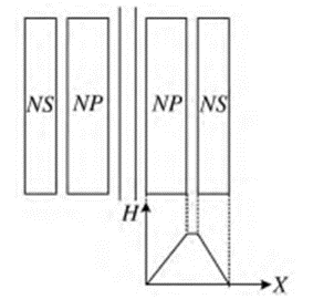
Figure 1. Winding layout and magnetic field distribution of simple winding structure [3].
2.2. Leakage inductance of three winding high frequency transformer
First, input voltage, core material, insulating material properties, temperature limit, and so on. Then, the core section size, the number of the core, the winding, the thickness of the coil, and so on. Then, the loss and leakage inductance are calculated, and the hot spot temperature is calculated. If the temperature of the hot spot is higher than the limit of the temperature rise, then it is necessary to re-select the free parameters. If the distance from the core to the iron core is determined by the insulation of the low voltage winding according to the design scheme of the double-winding structure, and then the leakage inductance is controlled by adjusting the distance between the primary coil and the primary coil, it will be difficult to regulate the high and low voltage leakage inductance and the middle and middle voltage leakage inductance simultaneously, since the location of the middle voltage coil will influence both leakage inductance. It is possible to control the leakage inductance to solve the above problem. First, the initial value between the high-voltage coil and the inner cylinder is determined, and then the distance d1 between the high-voltage coil and the middle voltage coil is calculated according to the design value of the leakage inductance. Then, based on the design value of the HV winding and the LV winding, the distance of the LV winding from the inner tube is calculated, and the distance of the LV winding from the inner tube is calculated, and the distance from the LV winding to the inner tube is determined to satisfy the design demand. If it does not meet the design requirement, the initial value of the high voltage winding must be adjusted to the inner cylinder. So long as the design requirements are met, it is possible to get the spacing between high, medium and low voltage windings. Finally, the leakage inductance between the middle and low windings can be calculated. Proper choice of insulation thickness and coil height reduces winding losses [4].
Leakage inductance and distributed capacitance of high frequency transformer can not only cause resonance, but also lead to a surge of current and voltage, which can easily damage the switch tube and increase the power loss. Leakage inductance and distribution capacity of high frequency transformer are mainly influenced by core material, winding structure, connecting method, winding height and insulating layer. The size of the leakage inductance and the size of the distributed capacitance are limited by the height of the coil and the insulation thickness. Reducing the leakage inductance increases the distributed capacitance; Vice versa. This makes it more difficult to design high frequency transformers. It is found that the leakage inductance is directly proportional to the thickness of the insulation layer, and is inversely proportional to the height of the winding. The results show that the distribution capacity decreases with the increase of the insulation thickness, and the distribution capacity increases with the increase of the winding height. Through the comparison of 3-D fitting and 3-D characterization of insulation layer thickness and winding height, the results show that when the insulation layer is 1.0 ~ 1.18 mm thick, the results show that: The winding height range is 26.8 ~ 33.8 mm, and the winding loss can be minimized [5].
2.3. High frequency transformer core material
More and more converter designs seek higher frequencies, thinner thicknesses, and higher power density, which makes magnetics increasingly important. Because of the appearance of high frequency switching elements, the size of the transformer and other magnetic elements has been reduced, and the researchers have chosen to achieve a higher power frequency density by means of higher operation. But there are a lot of advantages to doing so, but there are also unnecessary losses. The designer needs to optimize the design for the most appropriate system performance. High working frequency devices are suitable for maximum efficiency with minimum parasitics. The designers need to optimize the design and select the magnetics carefully, because the right core choice can eliminate the excessive ground temperature due to the loss of the core ground. Designers also need to balance the magnetic properties of the core, such as resistivity, saturation, and permeability. MnZn and NiZn are two kinds of flat transformer cores. It is widely used in high-frequency and high-resistivity situations, and has a dominant position in high-permeability and low-conductivity regions. Manganese zinc has better properties at frequencies below 2 MHz. Nickel and zinc have better properties in the range of 1 MHz, and they complement each other in terms of high resistivity and magnetoresistivity. Thus, the choice of nickel-zinc and manganese-zinc is completely determined by the operating frequency of their use.
Iron oxide (typically Fe2O3) may be mixed with other metallic materials (e.g., Mn, Zn, Ni, Co, Cu) to form a soft ferrite, and Mn Zn and Ni Zn are the most common soft ferrite. Due to its high resistance and low resistivity, it is more and more popular to use soft magnetox as the core material in making plane transformer. However, soft ferrites also have some disadvantages. First of all, SMMs have a minimum saturation flux density (usually 0.2 to 0.5 T). Second, the Curie temperature of soft ferrite is lower, which is the lowest in SMM. Thirdly, when using soft magnetic ferrites in inductors, the air gap is usually required to prevent saturation, which results in edge flux and extra loss. Fourth, soft ferrites are generally brittle and sensitive to mechanical shock, limiting their use in high-reliability scenarios [6].
There is a difference in temperature rise between manganese and zinc materials with different permeability and electrical resistivity. Due to the difference in permeability and electrical resistivity of magnetic cores, the manganese and zinc materials can be classified as A and B and C and D. The classification is as shown in Table 1.
Of the four materials, the temperature rise of material A is the least. The transformer is placed at a temperature of 25 ℃. Nevertheless, when working at 1 MHz, the temperature of the material A is 34 ℃. Meanwhile, the temperature increases of B, C and D cores are 39 ℃, 41 ℃ and 41 ℃, respectively. Therefore, 10W and 1MHZ are the most appropriate frequency and power for regular operation of the core of planar transformer, because of its high efficiency and heat stability.
It is found that the loss of A class materials is minimal at 1 MHz and 1 W power. The results show that material is the least stable among the four materials, and A material is the most stable [7].
Choose a suitable soft magnetic material to optimize the transformer core.
High frequency transformers (HFTs) have high core losses due to their high operating frequency and low flux saturation. The efficiency of the HFT is limited by the combination of core structure, magnetic material and winding. The new soft magnetic materials have the advantages of higher flux density, lower losses in middle and high frequency cores, and higher resistivity. High core losses that occur in high-frequency trading may be reduced [8].
2.4. High frequency transformer insulation and cooling
The influence of different fluids on the cooling properties of the transformer is different. Most commonly used in liquid immersion transformer is mineral oil, which is not only used as cooling medium, but also as information carrier and insulator. Improved fire safety and ease of biodegradation are the benefits that transformer operators are looking for in developing alternative converters. First of all, the paper constructs a zigzag winding model, then takes the mineral hydrocarbon transformer oil as the cooling medium, then takes the liquid and liquid hydrocarbon transformer oil and the synthetic ester transformer oil as the cooling medium of the transformer. The heat performance of the transformer is measured, and the heat performance of the three refrigerants is compared. Then, in the liquid cooling mode, the mineral based transformer oil and the gas liquid based transformer oil were observed. Comparison of the non-liquid cooling mode and the behavior shows that the liquid flow and the temperature distribution are similar. Compared with other oils, the flow profile of the synthetic esters is more uniform, and it has a delayed influence on the occurrence of the reverse flow. In the non-liquid cooling mode, the winding pattern is a zigzag disk, and the synthetic ester, due to its high viscosity, results in a lower inlet flow at the back filling conditions of the specific test, which results in an uneven distribution of the flow of oil in the channel, and a higher temperature of the hot spot [9].
It is very important to ensure the safety and stability of frequency transformer, and it is more important in high-frequency high-voltage transformer. Because high-frequency high voltage transformers have a high voltage level, they have a higher demand on their insulation properties. Leakage inductance and distributed capacitance are the main problems in high frequency transformer design. By analyzing and calculating the main insulation magnetic field of transformer, it is concluded that the insulation board is suitable for high frequency transformer. Because the insulation of the transformer takes up sufficient space in the transformer, the size of the transformer can be reduced by improving the configuration of the transformer so as to meet the insulation requirements [10].
As far as insulation and power density are concerned, one of the most important aspects of the solid-state transformer is the design of the DC/DC converter. High voltage processing requires more volume than conventional DC/DC converters because of the need for insulation. Proper selection of the switching frequency can increase the efficiency and the density of the power. The results show that the ML27D core is the best in the range of 200 ~ 300 kHz. The insulation structure of the transformer will be improved through the removal of excessive insulating materials and the compaction of the transformer. As illustrated in figure 2, the distribution of the electric field in the air and the coil is highest, and the field distribution in the epoxy resin is small. In the drawing, the red frame has no field distribution, and the output voltage is 400 V on the secondary side.Taking into account the insulation of transformer, it is found that there is no electrical field, which makes this area useless and takes up a lot of space, which also decreases the power density of transformer.
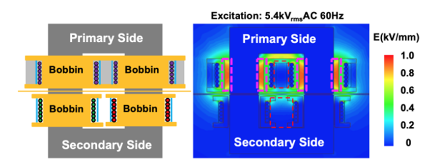
Figure 2. Transformer insulation design and E-field distribution [11].
To increase the utilization of space, figure 3 illustrates a novel multilayered winding structure, which not only compresses the structure of the transformer, but also removes excessive insulation. This makes it possible for the secondary winding to accommodate additional space. However, there is also a drawback of this approach: it makes the winding loss of the transformer slightly higher. Generally speaking, the benefits of such a new winding system far outweigh its drawbacks [11].
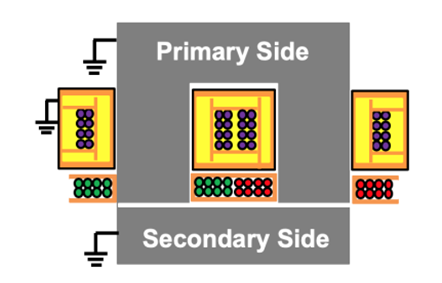
Figure 3. Proposed insulation structure [11].
3. Conclusion
High frequency transformer winding structure. There are three kinds of winding structure in high frequency transformer: simple winding, sandwich winding and cross winding. Using high frequency transformer leakage inductance control, the design of transformer winding is optimized by using the method of free parameter sweep. Proper choice of insulation thickness and winding height can reduce the loss of winding. The results show that the winding loss can be reduced to a minimum range when the thickness of the insulating layer is 1.0 ~ 1.18 mm and the winding height is 26.8 ~ 33.8 mm.
The results show that the core material of the high frequency transformer is MnZn and NiZn, and the results show that the core material of the high frequency transformer is MnZn and NiZn. Moreover, it is shown that the electrical conductivity of MnZn and NiZn is not only high, but also has low electrical conductivity. Moreover, there is a difference in temperature rise between manganese and zinc materials with different permeability and electrical resistivity. And the manganese-zinc material is divided into four categories of ABCD, and the four materials are placed under the condition of an ambient temperature of 25 ℃, and the study found that the temperature rise of material A is the smallest of the four materials, which indicates that the stability of material A is the best of the four materials.
The paper constructs a zigzag winding model, then takes the mineral hydrocarbon transformer oil as the cooling medium, then takes the liquid and liquid hydrocarbon transformer oil and the synthetic ester transformer oil as the cooling medium of the transformer. Compared to other oils, synthetic esters flow more uniformly, which has a delayed effect on the occurrence of reflux. In high-frequency high-voltage transformers, it is particularly important to ensure the safety and stability of frequency converters. Therefore, the requirements for insulation will be higher, and through the analysis and calculation of the main insulation magnetic field of the transformer, it is concluded that the insulation board is suitable for high-frequency transformers. Proper selection of switching frequency can improve power efficiency and density. The results show that in the range of 200~300 kHz, the performance of ML27D core is the best.
Transformer high frequency is the future development trend, because the advantages of high-frequency transformers are huge, and it is only a matter of time to replace traditional power frequency power transformers. Therefore, all countries in the world attach great importance to the development and manufacturing of high-frequency power transformers, and it is believed that in the near future, the power transformer market will usher in tremendous changes.
References
[1]. Kiran, M. R., Farrok, O., Islam, Md. R., & Zhu, J. (2019). Characterization of the Optimized High Frequency Transformer Using Nanocrystalline and Amorphous Magnetic Materials. 2019 22nd International Conference on Electrical Machines and Systems (ICEMS), 1–4.
[2]. Dira, Y. S., Tan, N. M. L., & Ramli, A. Q. (2020). A Review of High-Frequency Transformers for Bidirectional Isolated DC-DC Converters. 2020 IEEE International Conference on Power and Energy (PECon), 137–142.
[3]. Yang Huan, Zhang Junchao, Zhang Junhu, and so on. Effect of high frequency transformer winding layout on distribution parameters and power consumption [J], Journal of Shanxi University (Natural Science Edition), 2019,42 (03): 576-583.
[4]. YUAN Xuan, Li Lin, and LIU Ren. Optimum Design of Three Winding High Frequency Transformer [J]. 4523-4533.
[5]. WANG Qingzhuang, JIA Mingna, and ZHU Shengjie. Effect of high frequency transformer winding height and insulation thickness on distribution parameters. Modern Electronic Technology, 2022,45 (07): 148-151.
[6]. Z. Li, W, Z, Z Xin, Q Liu, J Chen, P. C. Loh, Core Loss Modeling and Measurement of High-Power High-Frequency Transformers, CPSS Transactions on Power Electronics and Applications, December 2022, 7(4) , 359-373.
[7]. M. K. Ahmad, M. S. Ali, A. Majid, J. Saleem and S. M. R. Kazmi, Comparison and analysis of core materials for high frequency (1MHz) planar transformers, 2018 International Conference on Computing, Mathematics and Engineering Technologies (iCoMET), Sukkur, Pakistan, 2018, 1-5.
[8]. Kiran, M. R., Farrok, O., Islam, Md. R., & Zhu, J. (2019). Characterization of the Optimized High Frequency Transformer Using Nanocrystalline and Amorphous Magnetic Materials. 2019 22nd International Conference on Electrical Machines and Systems (ICEMS), 1–4.
[9]. Daghrah, M., Wang, Z., Liu, Q., Hilker, A., & Gyore, A. (2019). Experimental Study of the Influence of Different Liquids on the Transformer Cooling Performance. IEEE Transactions on Power Delivery, 34(2), 588–595.
[10]. Zheng Zhihong. Analysis of High Frequency Transformer Heating Mechanism and Insulation Design [D],2016, 0-63.
[11]. Li, Z., Hsieh, Y.-H., Li, Q., Lee, F. C., & Ahmed, M. H. (2020). High-Frequency Transformer Design with High-Voltage Insulation for Modular Power Conversion from Medium-Voltage AC to 400-V DC. 2020 IEEE Energy Conversion Congress and Exposition (ECCE), 5053–5060.
Cite this article
Liu,Y. (2023). High-frequency transformers optimized design for power electronic transformers. Applied and Computational Engineering,10,196-202.
Data availability
The datasets used and/or analyzed during the current study will be available from the authors upon reasonable request.
Disclaimer/Publisher's Note
The statements, opinions and data contained in all publications are solely those of the individual author(s) and contributor(s) and not of EWA Publishing and/or the editor(s). EWA Publishing and/or the editor(s) disclaim responsibility for any injury to people or property resulting from any ideas, methods, instructions or products referred to in the content.
About volume
Volume title: Proceedings of the 2023 International Conference on Mechatronics and Smart Systems
© 2024 by the author(s). Licensee EWA Publishing, Oxford, UK. This article is an open access article distributed under the terms and
conditions of the Creative Commons Attribution (CC BY) license. Authors who
publish this series agree to the following terms:
1. Authors retain copyright and grant the series right of first publication with the work simultaneously licensed under a Creative Commons
Attribution License that allows others to share the work with an acknowledgment of the work's authorship and initial publication in this
series.
2. Authors are able to enter into separate, additional contractual arrangements for the non-exclusive distribution of the series's published
version of the work (e.g., post it to an institutional repository or publish it in a book), with an acknowledgment of its initial
publication in this series.
3. Authors are permitted and encouraged to post their work online (e.g., in institutional repositories or on their website) prior to and
during the submission process, as it can lead to productive exchanges, as well as earlier and greater citation of published work (See
Open access policy for details).
References
[1]. Kiran, M. R., Farrok, O., Islam, Md. R., & Zhu, J. (2019). Characterization of the Optimized High Frequency Transformer Using Nanocrystalline and Amorphous Magnetic Materials. 2019 22nd International Conference on Electrical Machines and Systems (ICEMS), 1–4.
[2]. Dira, Y. S., Tan, N. M. L., & Ramli, A. Q. (2020). A Review of High-Frequency Transformers for Bidirectional Isolated DC-DC Converters. 2020 IEEE International Conference on Power and Energy (PECon), 137–142.
[3]. Yang Huan, Zhang Junchao, Zhang Junhu, and so on. Effect of high frequency transformer winding layout on distribution parameters and power consumption [J], Journal of Shanxi University (Natural Science Edition), 2019,42 (03): 576-583.
[4]. YUAN Xuan, Li Lin, and LIU Ren. Optimum Design of Three Winding High Frequency Transformer [J]. 4523-4533.
[5]. WANG Qingzhuang, JIA Mingna, and ZHU Shengjie. Effect of high frequency transformer winding height and insulation thickness on distribution parameters. Modern Electronic Technology, 2022,45 (07): 148-151.
[6]. Z. Li, W, Z, Z Xin, Q Liu, J Chen, P. C. Loh, Core Loss Modeling and Measurement of High-Power High-Frequency Transformers, CPSS Transactions on Power Electronics and Applications, December 2022, 7(4) , 359-373.
[7]. M. K. Ahmad, M. S. Ali, A. Majid, J. Saleem and S. M. R. Kazmi, Comparison and analysis of core materials for high frequency (1MHz) planar transformers, 2018 International Conference on Computing, Mathematics and Engineering Technologies (iCoMET), Sukkur, Pakistan, 2018, 1-5.
[8]. Kiran, M. R., Farrok, O., Islam, Md. R., & Zhu, J. (2019). Characterization of the Optimized High Frequency Transformer Using Nanocrystalline and Amorphous Magnetic Materials. 2019 22nd International Conference on Electrical Machines and Systems (ICEMS), 1–4.
[9]. Daghrah, M., Wang, Z., Liu, Q., Hilker, A., & Gyore, A. (2019). Experimental Study of the Influence of Different Liquids on the Transformer Cooling Performance. IEEE Transactions on Power Delivery, 34(2), 588–595.
[10]. Zheng Zhihong. Analysis of High Frequency Transformer Heating Mechanism and Insulation Design [D],2016, 0-63.
[11]. Li, Z., Hsieh, Y.-H., Li, Q., Lee, F. C., & Ahmed, M. H. (2020). High-Frequency Transformer Design with High-Voltage Insulation for Modular Power Conversion from Medium-Voltage AC to 400-V DC. 2020 IEEE Energy Conversion Congress and Exposition (ECCE), 5053–5060.