


1. Introduction
Phase-locked loops (PLLs) have become an essential building block in modern communication systems, which has been applicated in wireless communication, data storage, clock generation, and frequency synthesis [1]. It has become a vital component in the design of high frequency systems because of the ability to generate a stable output signal with a well-defined phase relationship to an input signal. Even though, nowadays PLLs are widely used in many fields of high frequency systems designing, there are still many challenges that need to be addressed in the designing and implementation of PLLs, such as PLL stability, jitter, and power consumption. Moreover, the recent trend towards high-speed and low-power communication systems has also posed new challenges for PLL design, requiring novel approaches to improve their performance and efficiency. The paper will also give some information for aspects with less attention [2]. For example, the analysis of PLLs has mainly focused on the forward direction, where the output frequency is locked to the input frequency. However, in many applications, such as clock recovery, the PLL must operate in the reverse direction, where the input frequency is locked to the output frequency [3].
The paper will first present a comprehensive review of recent advances in PLL research, focusing on both the theoretical and practical aspects of PLL design and application. Then highlight the innovative approaches proposed by researchers to address the challenges associated with PLLs, including new architectures, advanced loop filters, and improved phase detectors. Additionally, we analyze the impact of these approaches on the performance of PLLs, some ignored aspects of PLLs designing and provide insights into how they can be further improved in the future.
2. Working principle and component of phase-locked loop
2.1. Working principle of PLL
According to its different working principles and methods, phase-locked loop (PLL) refers to a control system that can generate output signals with specific rules. By comparing different working principles, it can be found that the basic principle of PLL is to match the phase of the input signal again. This working method is significantly different from traditional output signals, which is achieved by adjusting the frequency of the locally generated signal, which in turn adjusts its phase [1]. This section will provide detailed information on how this principle works.
2.1.1. Feedback controlling in PLL circuit. Feedback controlling in the fundamental part of the whole principle. In a phase-locked loop (PLL), it is used to keep the phase and frequency of the output signal locked to the phase and frequency of the input signal. This process is achieved through a closed-loop control system that uses feedback to continuously adjust the phase and frequency of the local oscillator until it matches the input signal, in order to keep the system steady.
The feedback control in a PLL is based on the concept of phase detection. The phase detector compares the phase of the input signal with the local oscillator’s signal, and generates an error signal that is proportional to the phase difference between the them. This error signal is then fed back to the input of the local oscillator through a low-pass filter, which removes any high-frequency components from the signal.
As the local oscillator frequency is adjusted, the phase difference between the input signal and the local oscillator is reduced, and the error signal becomes smaller. Then this process will be repeated until the phase and frequency of the output signal match those of the input signal.
2.1.2. The generation and elimination of clock skew. Clock skew is a timing error that can occur in digital systems due to various factors. The following figure 1 is a simple wave which shows clock skew.
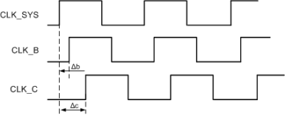
Figure 1. Clock skew [1].
Before explaining how PLLs address clock skew, here comes some common reasons for the happening of it:
(1) The delay in propagation of clock signals through a transmission line can result in clock skew. When clock signals travel through a transmission line, they will experience different delays due to factors such as the length of the transmission line, the impedance of the line, and what kind of material is used to make the line [2]. This delay can cause clock signals to arrive at different times and finally result in clock skew.
(2) Temperature and voltage variations can also cause clock skew in digital systems. The propagation delay of clock signals can vary with temperature and voltage changes, which can result in clock skew.
(3) Clock jitter is another factor that can cause clock skew. Clock jitter is the variation in the timing of clock signals due to noise or interference. This can also cause a deviation of the arriving of clock signals.
However, PLL can solve the problem of clock skew in digital systems. It can generate a clock signal that is synchronized with an input clock signal or a reference clock signal, and then eliminates any differences in timing between these signals.
In order to do this, a PLL compares the phase and frequency of the input clock signal or reference clock signal with the phase and frequency [3]. This comparison is done by a phase detector, which generates an error signal that is proportional to the phase and frequency difference between the two signals, just as the description above in the introduction of feedback control.
By using feedback control to adjust the frequency and phase of the locally generated clock signal, the PLL will be able to eliminate any differences in timing between the input clock signal or reference clock signal. This ensures that the clock signals in the digital system are properly synchronized [4].
2.1.3. Frequency multiplying. A frequency multiplier in PLL can take an input signal and produces an output signal whose frequency is a multiple of the input frequency. It can be implemented using various circuit techniques, such as frequency doublers, triplers, or higher order multipliers.
In the context of a PLL, the frequency multiplier is typically implemented using a nonlinear device, such as a diode, transistor, or a mixer, that performs a multiplication operation on the input signal.
The multiplication factor (M) of the frequency multiplier determines the how much times the frequency of locally generated clock signal is increased. For example, if the input clock signal has a frequency of 10 MHz, and the multiplication factor of the frequency multiplier is 4, then the output clock signal would have a frequency of 40 MHz.
2.2. Components of PLL
The following figure 2 shows the basic circuit of PLL, from which you can clearly see its specific working principle and structural composition. Through investigation and research, it was found that this structure has good resistance to external interference and fluctuations, and can maintain the stability of the entire system.
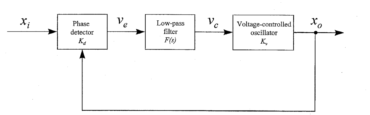
Figure 2. Basic circuit of PLL [1].
The following three parts will explain these three components specifically.
2.2.1. Phase detector. The importance of a phase detector is self-evident. As a core processing component in control, its main function is to assist and identify signal errors, to help the entire system maintain a high degree of accuracy and precision at all times, and to avoid affecting the working output due to excessive errors.
For example, the square signal PD (Phase Detector) is widely used in the designing of PLLs. The characteristics of the square signal PDs has the linear type over the phase detection, while triangular PDs and sawtooth PDs have different types of phase detection [5]. The following figure shows the characteristics of phase detector mentioned above. Figure 3 is the characteristics of the phase detector.
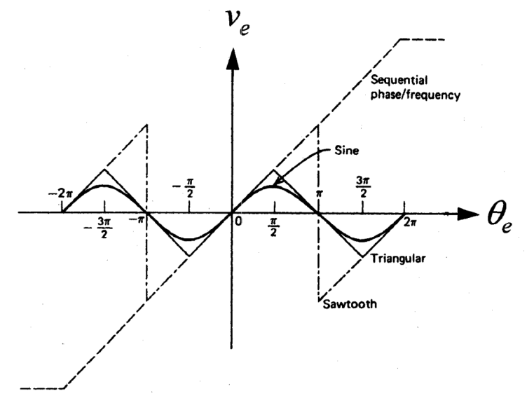
Figure 3. Characteristics of the phase detector [1].
2.2.2. Low-pass filter. Among all the structural components of PLL, there is also a very important one, which plays a role in eliminating noise and ensuring the stability of the entire system's output current signal. Low pass filter is a very important component, so it is necessary to choose the relevant parameters and working environment reasonably when selecting and designing.
The output of the phase detector, which is proportional to the phase error, contains high-frequency components that need to be filtered out before it is used to adjust the voltage-controlled oscillator (VCO). If these high-frequency components are not filtered out, they will cause the VCO to produce an unstable output signal, then result in jitter or frequency instability [6].
2.2.3. Voltage-controlled oscillator. A voltage-controlled oscillator (VCO) plays the role generating an output signal with a frequency that is synchronized to a reference input signal. By applying a control voltage to the resonant circuit, the frequency of the output signal can be adjusted. The VCO operates by generating a sinusoidal waveform, with a frequency that is a function of the input voltage applied to it. The frequency range of the output signal is typically determined by the components in the resonant circuit, such as the inductors and capacitors [7].
3. Applications and challenges of phase-locked loop
3.1. Applications of PLL
PLL has a wide range of applications in electronic systems where frequency synchronization is required. Some common applications include clock generation in digital systems, frequency synthesis in radio and communication systems. and synchronization of power supply frequencies. The next two part include the application in frequency synthesizer as well as the recovery of clock and data in digital systems [8].
3.1.1. Frequency synthesizer. A frequency synthesizer is an electronic circuit that generates a stable and accurate output signal with a frequency that can be varied over a wide range of values [8]. A Phase Locked Loop (PLL) is often used in frequency synthesizers to generate the desired output frequency.
The PLL acts as a closed-loop control system that compares the frequency of a reference input signal with the output frequency of a voltage-controlled oscillator (VCO). Any phase difference between the two signals would be processed by PLL's feedback loop, resulting in a DC voltage that is proportional to the phase error.
This DC voltage is then used to adjust the input voltage of the VCO, which in turn adjusts the frequency of the output signal until it fits the reference input signal. By controlling the input voltage of the VCO, the PLL can generate a stable and accurate output signal with a frequency that is a multiple of the reference input frequency.
Frequency synthesizers that use PLLs are widely used in communication systems, where the ability to generate precise and stable frequencies is critical [9]. They are nowadays used in cell phones, Wi-Fi routers, satellite communication systems, and many other applications where frequency control and stability are essential.
3.1.2. Clock and data recovery. A Clock and Data Recovery (CDR) circuit is an electronic circuit used to extract a clock signal and data from a serial data stream. A Phase Locked Loop (PLL) is often used in CDR circuits to generate a stable and accurate clock signal. By controlling the input voltage of the VCO, the PLL can generate a stable and accurate clock signal that is synchronized to the data signal.
CDR circuits that use PLLs are widely used in communication systems, where the ability to accurately recover clock and data signals is essential. They are used in high-speed serial communication interfaces such as Ethernet, USB, and SATA, where the data rate is in the Gbps range.
3.2. Challenges of PLL
Although PLLs are widely used in many electronic applications, they face several challenges. For example, PLLs are sensitive to noise and unwanted signal components that can affect their output frequency stability and accuracy. Noise can be introduced from various sources such as power supply, substrate, and external interference [10]. So, a novel architecture is needed in order to improve the performance of PLLs, and more accurate phase detectors are also required.
3.2.1. New architectures used in PLL designing. Over the years, various new architectures have been proposed for the design of Phase Locked Loops (PLLs) to overcome the challenges faced by traditional PLLs and to improve their performance. Here are some examples of new PLL architectures:
(1) Fractional-N PLL: The Fractional-N PLL is a modified version of the traditional integer-N PLL that allows the PLL to generate frequencies that are non-integer multiples of the reference frequency.
(2) All-digital PLL: The All-digital PLL (ADPLL) uses only digital circuits, eliminating the need for analog components such as VCOs and filters [11]. ADPLLs offer several advantages over traditional PLLs, including better scalability, lower power consumption, and higher immunity to noise.
(3) Bang-Bang PLL: The Bang-Bang PLL uses a digital phase detector and a switched capacitor filter to achieve high frequency resolution and low phase noise. This architecture is suitable for low-power applications and has been used in frequency synthesizers for wireless communication systems.
These new PLL architectures have contributed to the advancement of PLL technology and have enabled the design of PLLs with improved performance, scalability, and power efficiency [12].
3.2.2. Advanced loop filters and improved phase detectors in PLL designing. Loop filters and phase detectors are critical components of a Phase Locked Loop (PLL), as they determine the stability, noise performance, and locking time of the PLL. Over the years, several advanced loop filters and improved phase detectors have been developed to address the challenges faced by traditional PLLs and improve their performance [13]. Here comes some examples:
(1) Proportional-Integral (PI) loop filters: PI loop filters are commonly used in PLLs due to their simplicity and good stability characteristics. However, they can suffer from poor transient response and phase noise. To address this, advanced PI loop filters have been developed that use non-linear elements such as RC filters, resonators, or active elements to improve the PLL's performance.
(2) Charge-pump phase detectors: Charge-pump phase detectors are widely used in PLLs due to their simplicity and good performance. However, they can suffer from offset errors, which can cause phase noise and limit the PLL's locking range. To address this problem, improved charge-pump phase detectors have been developed that use current-mirror techniques, self-calibration circuits, or multi-level quantization to reduce offset errors [14].
(3) Digital phase detectors: Digital phase detectors offer several advantages over analog phase detectors, including better accuracy, programmability, and noise performance. But they will be influenced by delay errors and quantization noise [15]. In order to solve this problem, improved digital phase detectors have been developed that use delay-locked loops, dynamic latches, or multi-phase clocking to improve their performance.
These advanced loop filters and improved phase detectors have contributed to the development of PLLs and significantly improve their performance, stability, and noise characteristics, making them more suitable for a wide range of applications in communication systems, radar, instrumentation, and other fields.
4. Prospects and discussion
Phase-Locked Loop (PLL) technology has come a long way since its inception and has found extensive applications in various domains such as telecommunications, data storage, and wireless communication. However, there is still a great potential for further developments and improvements in PLL technology.
A potential development of PLL technology is the introduction of new architectures and designs [16]. New designs such as fully digital PLL (ADPLL) and fractional N PLL have been developed. These new designs have improved performance, reduced power consumption, and made them more suitable for modern applications.
Another potential development is the use of advanced loop filters and phase detectors. The loop filter is an essential component of a PLL, and its performance plays a significant role in the overall system. Similarly, improved phase detectors, such as the Bang-Bang phase detector, have been developed to offer better performance and reduced power consumption.
Furthermore, PLL technology has the potential to be used in emerging technologies such as 5G wireless communication, Internet of Things (IoT), and artificial intelligence. The increasing demand for high-speed communication and low-latency systems also requires the development of new PLL designs that can offer better performance and stability in these systems. PLL technology can be used in AI applications as well, such as machine learning, where accurate timing signals are required.
5. Conclusion
In conclusion, the Phase-Locked Loop (PLL) is an essential component in electronics, providing stable output frequency and eliminating clock skew. The feedback controlling with PLLs adjusts and maintains frequency stability. Meanwhile, there are still many challenges in its design including developing new architectures and optimizing modules like loop filters and phase detectors. With the increasing demand for higher performance and accuracy, we can expect further research and development in the field of PLLs to continue pushing the boundaries of what is possible.
References
[1]. Hsieh G C., Hung J C. (1996) Phase-locked loop techniques. IEEE Transactions on industrial electronics, 43(6): 609-615.
[2]. Ahmad S., Mekhilef S., Mokhlis H. (2021) An improved power control strategy for grid‐connected hybrid microgrid without park transformation and phase‐locked loop system. International Transactions on Electrical Energy Systems, 31(7): 12922.
[3]. Xu W., Huang C., Jiang H. (2021) Analyses and enhancement of linear Kalman-filter-based phase-locked loop. IEEE Transactions on Instrumentation and Measurement, 70: 1-10.
[4]. Gautam S., Xiao W., Lu D D C., Ahmed H., Guerrero J M. (2021) Development of frequency-fixed all-pass filter-based single-phase phase-locked loop. IEEE Journal of Emerging and Selected Topics in Power Electronics, 10(1): 506-517.
[5]. Zhang Z., Schuerhuber R., Fickert L., Friedl K., Chen G., Zhang Y. (2021) Domain of attraction’s estimation for grid connected converters with phase-locked loop. IEEE Transactions on Power Systems, 37(2): 1351-1362.
[6]. Ahmad S., Mekhilef S., Mokhlis H., Karimi M., Pourdaryaei A., Ahmed T., Afzal S. (2021) Fuzzy logic-based direct power control method for pv inverter of grid-tied ac microgrid without phase-locked loop. Electronics, 10(24): 3095.
[7]. Xu J., Qian H., Bian S., Hu Y., Xie S. (2020) Comparative study of single-phase phase-locked loops for grid-connected inverters under non-ideal grid conditions. CSEE Journal of Power and Energy Systems, 8(1): 155-164.
[8]. Li T., Zhou J., Liu S., Shi J., Ren F. (2020) Phase-locked loop based cancellation of ECG power line interference. ZTE Communications, 16(1): 47-51.
[9]. Mamonov S. S., Ionova I. V., Harlamova A O. (2022) Hidden synchronization of phase-locked loops with nonlinear delay. Itogi Nauki i Tekhniki. Seriya" Sovremennaya Matematika i ee Prilozheniya. Tematicheskie Obzory", 216: 88-96.
[10]. Hamed H. A., El Moursi M S. (2019) A new type-2 PLL based on unit delay phase angle error compensation during the frequency ramp. IEEE Transactions on Power Systems, 34(4): 3289-3293.
[11]. Xia T., Zhang X., Tan G., Liu Y. (2020) All-pass-filter-based PLL for single-phase grid-connected converters under distorted grid conditions. IEEE Access, 8: 106226-106233.
[12]. Du H., Sun Q., Cheng Q., Ma D., Wang X. (2019) An adaptive frequency phase-locked loop based on a third order generalized integrator. Energies, 12(2): 309.
[13]. Sadeque F., Benzaquen J., Adib A., Mirafzal B. (2020) Direct phase-angle detection for three-phase inverters in asymmetrical power grids. IEEE Journal of Emerging and Selected Topics in Power Electronics, 9(1): 520-528.
[14]. Wu J., Chen S., Hu K., Zheng L., Sun W. (2020) A low jitter multiplying delay-locked loop with static phase offset elimination applied to time-to-digital converter. Microelectronics Journal, 106: 104926.
[15]. Khalatpour A., Reno J L., Hu, Q. (2019) Phase-locked photonic wire lasers by π coupling. Nature Photonics, 13(1): 47-53.
[16]. Belila A., Amirat Y., Benbouzid M., Berkouk E M., Yao G. (2020) Virtual synchronous generators for voltage synchronization of a hybrid PV-diesel power system. International Journal of Electrical Power & Energy Systems, 117: 105677.
Cite this article
Li,J. (2023). Working principle and application analysis of phase-locked loop. Applied and Computational Engineering,11,174-180.
Data availability
The datasets used and/or analyzed during the current study will be available from the authors upon reasonable request.
Disclaimer/Publisher's Note
The statements, opinions and data contained in all publications are solely those of the individual author(s) and contributor(s) and not of EWA Publishing and/or the editor(s). EWA Publishing and/or the editor(s) disclaim responsibility for any injury to people or property resulting from any ideas, methods, instructions or products referred to in the content.
About volume
Volume title: Proceedings of the 2023 International Conference on Mechatronics and Smart Systems
© 2024 by the author(s). Licensee EWA Publishing, Oxford, UK. This article is an open access article distributed under the terms and
conditions of the Creative Commons Attribution (CC BY) license. Authors who
publish this series agree to the following terms:
1. Authors retain copyright and grant the series right of first publication with the work simultaneously licensed under a Creative Commons
Attribution License that allows others to share the work with an acknowledgment of the work's authorship and initial publication in this
series.
2. Authors are able to enter into separate, additional contractual arrangements for the non-exclusive distribution of the series's published
version of the work (e.g., post it to an institutional repository or publish it in a book), with an acknowledgment of its initial
publication in this series.
3. Authors are permitted and encouraged to post their work online (e.g., in institutional repositories or on their website) prior to and
during the submission process, as it can lead to productive exchanges, as well as earlier and greater citation of published work (See
Open access policy for details).
References
[1]. Hsieh G C., Hung J C. (1996) Phase-locked loop techniques. IEEE Transactions on industrial electronics, 43(6): 609-615.
[2]. Ahmad S., Mekhilef S., Mokhlis H. (2021) An improved power control strategy for grid‐connected hybrid microgrid without park transformation and phase‐locked loop system. International Transactions on Electrical Energy Systems, 31(7): 12922.
[3]. Xu W., Huang C., Jiang H. (2021) Analyses and enhancement of linear Kalman-filter-based phase-locked loop. IEEE Transactions on Instrumentation and Measurement, 70: 1-10.
[4]. Gautam S., Xiao W., Lu D D C., Ahmed H., Guerrero J M. (2021) Development of frequency-fixed all-pass filter-based single-phase phase-locked loop. IEEE Journal of Emerging and Selected Topics in Power Electronics, 10(1): 506-517.
[5]. Zhang Z., Schuerhuber R., Fickert L., Friedl K., Chen G., Zhang Y. (2021) Domain of attraction’s estimation for grid connected converters with phase-locked loop. IEEE Transactions on Power Systems, 37(2): 1351-1362.
[6]. Ahmad S., Mekhilef S., Mokhlis H., Karimi M., Pourdaryaei A., Ahmed T., Afzal S. (2021) Fuzzy logic-based direct power control method for pv inverter of grid-tied ac microgrid without phase-locked loop. Electronics, 10(24): 3095.
[7]. Xu J., Qian H., Bian S., Hu Y., Xie S. (2020) Comparative study of single-phase phase-locked loops for grid-connected inverters under non-ideal grid conditions. CSEE Journal of Power and Energy Systems, 8(1): 155-164.
[8]. Li T., Zhou J., Liu S., Shi J., Ren F. (2020) Phase-locked loop based cancellation of ECG power line interference. ZTE Communications, 16(1): 47-51.
[9]. Mamonov S. S., Ionova I. V., Harlamova A O. (2022) Hidden synchronization of phase-locked loops with nonlinear delay. Itogi Nauki i Tekhniki. Seriya" Sovremennaya Matematika i ee Prilozheniya. Tematicheskie Obzory", 216: 88-96.
[10]. Hamed H. A., El Moursi M S. (2019) A new type-2 PLL based on unit delay phase angle error compensation during the frequency ramp. IEEE Transactions on Power Systems, 34(4): 3289-3293.
[11]. Xia T., Zhang X., Tan G., Liu Y. (2020) All-pass-filter-based PLL for single-phase grid-connected converters under distorted grid conditions. IEEE Access, 8: 106226-106233.
[12]. Du H., Sun Q., Cheng Q., Ma D., Wang X. (2019) An adaptive frequency phase-locked loop based on a third order generalized integrator. Energies, 12(2): 309.
[13]. Sadeque F., Benzaquen J., Adib A., Mirafzal B. (2020) Direct phase-angle detection for three-phase inverters in asymmetrical power grids. IEEE Journal of Emerging and Selected Topics in Power Electronics, 9(1): 520-528.
[14]. Wu J., Chen S., Hu K., Zheng L., Sun W. (2020) A low jitter multiplying delay-locked loop with static phase offset elimination applied to time-to-digital converter. Microelectronics Journal, 106: 104926.
[15]. Khalatpour A., Reno J L., Hu, Q. (2019) Phase-locked photonic wire lasers by π coupling. Nature Photonics, 13(1): 47-53.
[16]. Belila A., Amirat Y., Benbouzid M., Berkouk E M., Yao G. (2020) Virtual synchronous generators for voltage synchronization of a hybrid PV-diesel power system. International Journal of Electrical Power & Energy Systems, 117: 105677.