


1. Introduction
Even though human beings mostly have their homeland on lands, the underwater world is nonetheless a challenging part that induce exploring. Recent years, communication scientists turn their eyesight on the hydrosphere to find a efficiently and securely technique. However, even though the underwater communication technology has achieved a development in wired and wireless techniques, the acoustic waves or electromagnetic waves have limitations in water qualities, which affect the transmit speed [1]. Built on that, the underwater optical communication becomes a focus of the research, for its high bandwidth and low delay [2].
In 1953, Duntley discovered that the ocean's absorption of light waves with wavelengths between 450 and 550 nm (blue and green lights, respectively) is less than that of other wavelengths [3]. Additionally, Gilbert's experiment from 1966 supported this trait[4]. In 1995, the Woods Hole Marine Research Institute (WHOI) successfully transmitted a 10 Mbit/s wireless signal at a distance of 20 m in pure, dark water using the visible communication method [5]. After 1980, America made an effort to demonstrate it in adverse environments, such as torrential downpours, foggy seas, and other challenging circumstances [5]. The results revealed that the communication functioned regularly [5]. Tivey stated in 2004 that low-power connected devices have the capability of optical transmission over brief underwater distances [5]. In order to lower expenses and obtain data transmission rates of 10 to 20Mbit/s over a 100m range, the WHOI team combined the optical system with the acoustic system in 2010 [5]. Li Jing developed a single photon, optical pulse, and carrier-modulated optical pulse Monte-Carlo modeling algorithm model in 2013 [5]. The maximum distance for carrier-modulated transmission under three different seawater quality parameters was determined in 2013 by incorporating carrier-modulated signals into the model and using Gaussian function modulation: 140 m for ocean water, 75 m for offshore water, and 19 m for gulf water [5].
A high-speed underwater laser transmission system based on Digital Pulse Interval Modulation (DPIM) technology is designed and verified by Wen Duanqiang in 2017. The system is inexpensive, uses little electricity, and has a lot of real-world applications. It can reach a high rate of 1 Mbit/s and a distance between ends of 50 m as long as the bit error rate remains within a certain range. In 2017, the optical communication laboratory of Zhejiang University accomplished 9.51 Gb/s converged data transmission based on red, green, and blue light in the underwater channel at a length of 10m [6]. The same year, a green laser diode-based underwater optical communication system was suggested by the Fudan University research team, which was modulated with NRZ-OOK, and 34.5m and 2.7Gbps of data transfer were made possible [6]. This system's top transmission capacity is anticipated to be 62.7 m, and its top bandwidth is 1 Gbps [6]. Li used a vertical cavity surface-emitting laser for the first time in 2018, achieving a high transfer rate of 5.2 Gbit/s over a 6 m distance [5]. Hong employed QAM based on probabilistic shaping for the first time in 2019, resulting in communication over a 35 m sub-water channel. Up to 12.64 Gbit/s of net data can be transmitted [5].
This paper mainly researches on the theory of underwater optical system and its communication channel characteristic.
2. Principle
In 1953, Duntley made the discovery that the ocean's attenuation of light is obviously smaller for blue and green lights than for other colors [3]. This finding led to the development of underwater optical transmission. Moreover, this wave band has a moderately excellent capacity to penetrate, good direction, and a short time delay.Figure 1.
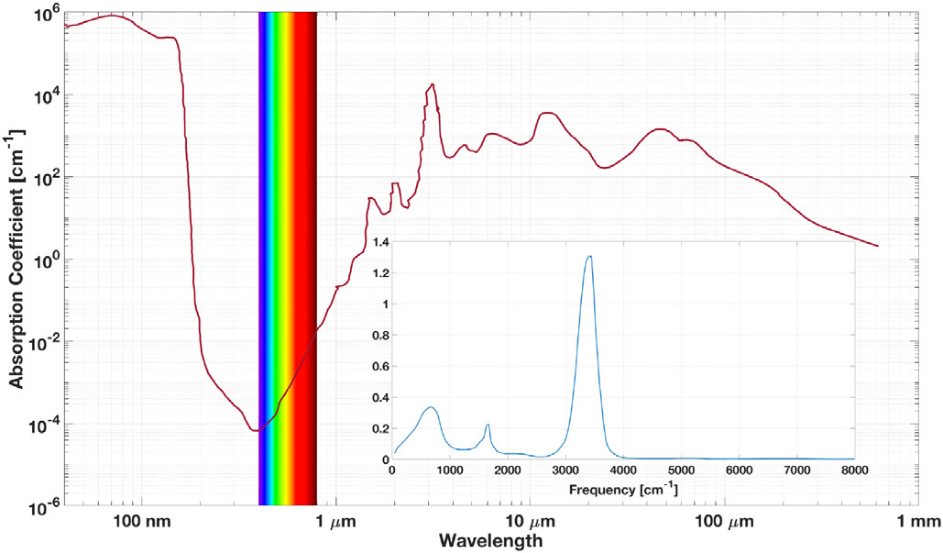
Figure 1. The attenuation effect of ocean for different wavelength of light [7]
Figure 2 shows the experiment principle of Saudi Arabia King Abdullah University of Science and Technology in 2015, at a bias voltage of 517.7 volt, one-mile-long water tank is passed by the highest emission wavelength, which is about one nanometer. Water in that has an attenuation value of 0.568. The length is multiplied by the reflection to become 7 miles. A high sensitivity silicon APD (Menlo Systems APD210) detector is used in the other terminal to receive the signal [8].
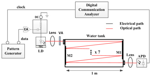
Figure 2. The sketch map of the experiment of Saudi Arabia King Abdullah University of Science and Technology [8].
Due to the complexity of the ocean, which may contain marine life, floating trash, pollution, and turbulence, the features of the specific marine are variable and call for further study. Light is attenuated in seawater despite the fact that it flows through it at a high speed due to significant absorption and scattering effects. Wave shape distortion arises after the entire signal has been synthesized, exacerbating code crosstalk and increasing bit error rate. The unstable underwater wire-free optical communication (UWOC) system, which also affects communication quality, will be a result of the erratic saltwater environment [9]. Therefore, it is crucial to take the transmission channel characteristic into account.
It is important to consider how well a laser can travel through water. Sea water absorbs and scatters light, and the absorption coefficient changes with depth and time. The absorbency is strong in the near sea area, but weak in the far sea area. In the same body of water, the absorption coefficient of sea water usually decreases with increasing depth. Scattering also gives a serious impression of the communication capability and mechanism, and also reduces the optical signal power.
The state of photons in water can be accurately simulated using the Monte Carlo technique. This can be used to compute and solve the random photon transmission process under water.
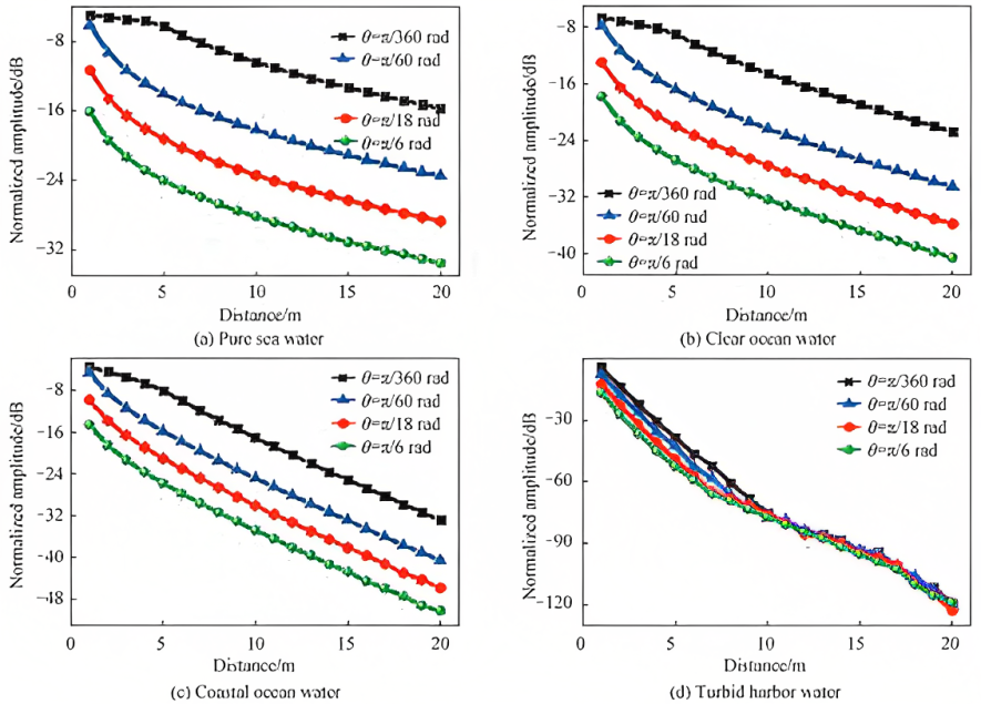
Figure 3. Normalized amplitude of received power [10].
The relationship between the received power, divergence angle, and transmission distance of various types of seawater under well water is simulated in Figure 3 using the Monte Carlo technique.
This suggests that the better the water quality, the higher the receiving capacity, and the better the ability of light to propagate, the smaller the dispersion Angle. \( θ=π/360 \) rad propagation distance at 5 m. Since most photons fall within the receiver diameter range and the projection circle diameter RS has a tiny difference from the receiver diameter of 0.04 m, the power is not changing considerably. The RS of a transmission distance of 1 m is 0.0574 m, and that of a transmission distance of 2 m is 0.1097 m, both of which are far distant when \( θ=π/60 \) rad. The RS at \( θ=π/18 \) rad and \( θ=π/6 \) rad will be bigger than 0.04 m receiver diameter. Therefore, it shifts to the receiver as the transmission distance grows. The shift in received power will be more noticeable because there won't be as many photons in the diameter range. When there is a tiny divergence angle and the transmission distance is greater than 5 m, RS is used. It is also bigger than the receiver's diameter, and as transmission distance increases, the receiving power declines more quickly and the change is more noticeable. And in 3(c) and 3(d), the majority of photons disperse in all directions during the propagation process, while the receiver only receives a small number of photons. As a result, the received strength only depends on the transmission distance and not the transmission angle [10].
Beer-Lambert formula describe the attenuation of the light that have a power \( {P_{i}} \) and when passing through ocean, where power \( {P_{a}} \) is absorbed, power \( {P_{s}} \) is scattered, and power \( {P_{c}} \) is still transmitted along the initial direction that will have a final power [9]:
\( p={p_{0}}{*e^{(-cl)}} \) (1)
where \( {p_{0}} \) is the original power, p is the after power for light to travel a distance l, and c is the attenuation coefficient, which equals to \( c=a+b \) , absorption coefficient is \( a=\underset{∆D→0}{lim}{\frac{{P_{a}}}{Pi∆D}} \) and scattering coefficient is \( b=\underset{∆D→0}{lim}{\frac{{P_{s}}}{Pi∆D}} \) . The accompanying chart displays the coefficient for the typical ocean type.
Table 2. The correlation coefficient of four types of seawater [9].
Seawater types | a | b | c |
Pure seawater | 0.053 | 0.003 | 0.056 |
Clear seawater | 0.114 | 0.037 | 0.151 |
Coastal seawater | 0.179 | 0.219 | 0.398 |
Turbid seawater | 0.295 | 1.875 | 2.17 |
The OOK modulate technique is a technique that one amplitude is zero and the other amplitude is non-zero.Robustness which mentioned in 3.2 means that the survive capacity for a system when facing dangerous.
3. Techniques to improve underwater optical communication: introduction, induction, and analysis
3.1. Light source technology
3.1.1. Dual light sources. As depicted in Figure 4. The system consists of the following components: an Ethernet module, an FPGA sending module, a data selector module, an excitation optical emission module, an LED driver module, an LED array module, a photoelectric connection receiving module, a photoelectric conversion module, a signal amplification processing circuit, an FPGA receiving module, an RS codec module, and a host unit [11].
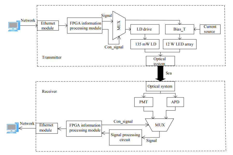
Figure 4. The overall structure diagram of the system [12].
The characteristic of this system is the dual light source, which effectively reinforce the communication velocity, and decrease the error rate. Using the OOK modulate technique, the Digital modulation characteristic graph is shown in Figure 5. The threshold current of the LED is set by the feedback electricity, and the LED is in a critical on-off state [12]. By digitally modulating the current, the LED generates different sizes of optical power. As introduced in theory when the digital signal is “0”, the current passing through is \( {I_{bias}} \) and when the digital signal is nonzero (or “1”), the current passing through is \( {I_{bias}}+{I_{mod}} \) , the difference of current cause the difference of power. And using the photodetectors measure different optical powers to transmit signals [12].
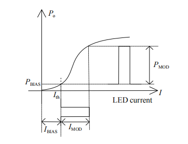
Figure 5. LED digital modulation characteristic curve [12].
3.1.2. LED array light source method. The attenuation effect of light is huge underwater, and a single LED has a limited function distance. Hence, It is effective to expand a single LED light source into multiple LED arrays to increase the communication distance of the system.
Researchers from the Massachusetts Institute of Technology created a two-way underwater wireless optical communication system in 2010. Six 5W blue LEDs are shown in an array and detector in Figure 6 at a 30m propagation distance. In the test pool with clean water, the transmission rate achieved 1.2 Mbit/s; in the pool with an estimated 3 M visibility, the data speed is 0.6 Mbit/s when the distance is 9m [13]. An array of six LEDs connected in series was used by researchers at the University of Skclyde in the UK in 2019 to reach a maximum transfer rate of 3.4 Gbit/s in 4.5 m of clear water [14].
Jin created a 7-in-1 LED light source array device in 2014. The LED array's divergence angle after collimation is 12° after placement. The system effectively lessens the impact of light energy divergence on transmission distance when compared to the high-power LED, whose divergence angle can reach up to 140°. Figure 7 depicts the broadcast signal along with the receiver's amplified digital signal.
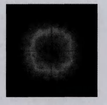
Figure 6. Spot in propagating 1m distance after collimation.
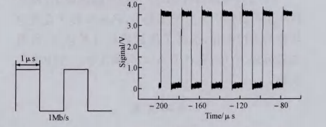
Figure 7. The transmitted signal and the amplified digital signal obtained by the receiver.
The following is a comparison of the advantages of LED and LD as light sources. LED array is used more frequently as a communication light source. This structure has two outstanding advantages, firstly, it can increase the transmitted light power; Secondly, it can improve the stability of the light source, that is, it can continue to use the communication light source when a single LED is damaged [9]. Additionally, the transmission distance of LD-based underwater wireless optical communication systems will be significantly increased; in comparison to LEDs, the system has a greater transmission rate over the same distance. Because of this, LD is ideal for high-speed, long-distance underwater wireless optical transmission systems [9].
3.2. Channel coding technique
The communication signal will be distorted and contain some errors when it is received due to the properties of the transmission channel and the impact of various noises generated during transmission on the communication process. The system's robustness can be increased, and the bit error rate can be decreased, by the inclusion of a channel coding module, also known as an error control coding module [15].The forward error correction (FEC) can be applied to achieve this. Block and convolutional algorithms make up the bulk of FEC. Block codes like Reed-Solomon, Bose Chaudhuri Hocquenghem, and Cyclic Redundancy Check reduce bandwidth at the cost of increasing link range and power efficiency [9].The convolutional codes LDPC and turbo are mainly introduced here;
3.2.1. LDPC code. LDPC code is a linear block code with a sparse check matrix. The check matrix, also known as the row weight and column weight, has a very small amount of non-zero elements per row and column relative to the length of each row and column. The LDPC code is referred to as regular LDPC code if the row weight and column weight of the parity matrix H stay constant (or uniform); otherwise, it is referred to as irregular LDPC code if the row weight and column weight change significantly. According to the research, irregular LDPC codes that are properly designed work better than regular LDPC codes [15].
The Tanner diagram is another significant depiction of LDPC codes in addition to the sparse check matrix as Figure 8 A route is a limited series of alternating nodes and edges that begins and ends at a node in the Tanner diagram. Each node only occurs once in the sequence, and each edge is connected to the node before it and the node after it. The length of a route is determined by how many edges are present. In the Tanner diagram, a path is created as a loop, or cycle, when the start and end nodes of a path coincide. The ring length is the length of the route that corresponds to the ring; The ring length with the shortest path length among all the rings in the graph is the girth of the Tanner graph. When iterative confidence propagation is used for decoding, the existence of short loops will limit the decoding performance of LDPC codes and prevent the decoding from converging to maximum likelihood decoding MLD. Therefore, the Tanner graph of LDPC code cannot contain short rings, especially rings of length 4 [16].
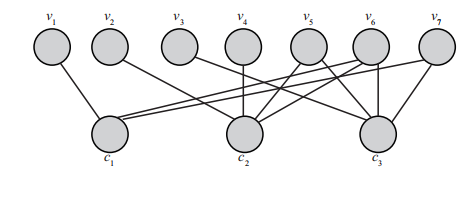
Figure 8. (7,4) Tanner diagram of linear block codes [16].
3.2.2. Turbo code. Due to their low coding complexity and relatively advanced technology, turbo codes have clear benefits in medium and short code lengths and joint design in communication systems. The throughput and decoding capabilities of Turbo codes are prioritized in real application design. Component decoders in conventional turbo codes alternately decode in serial mode after receiving a complete frame of data. Decoding takes a long time as a consequence. It does not satisfy the ITE's requirements for deciphering delay. As a result, parallel decoding mechanisms are now used with turbo codes. Break up N long data blocks into M smaller pieces (M is called parallelism). Each subblock is translated by a separate SISO decoding module (FIGURE 9 depicts its translator structure, M = 4 in the figure), which includes functional modules for branch metric calculation, forward and backward state metric calculation, and LLR calculation. By increasing the hardware expense in comparison to the conventional string line decoding structure, the decoding delay can be decreased to 1 / M and the data rate can be multiplied by M [16].
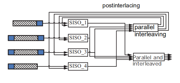
Figure 9. Turbo code parallel decoding structure [16]
Using good channel coding technology can improve the propagation rate of underwater optical communication and reduce the bit error rate. The above two coding technologies can do this effectively.
3.3. Detection (receiving) technology
3.3.1. Receiving end alignment and EKF method. First, using Gaussian light as the light source and based on the Mi scattering theory, the Monte Carlo technique to simulate the transmission characteristics of photons in the underwater laser communication channel. The weight of the photon that was received determines the brightness of the received location. The distribution relationship between the normalized light intensity at the receiving end in one-dimensional space and the distance r between the photosensitive surface of the receiver and the spot center under different transmission distances is obtained through simulation analysis of the photon distribution at the receiving end when the communication link is 10m, 15m, 20m, and 25m, as shown in Figure 10. The Gaussian function is then used to fit the distribution relationship [17].
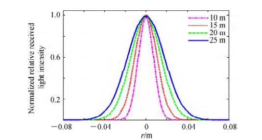
Figure 10. The normalized intensity distribution under different transmission distance [17].
Then, using the EKF [18] method to estimate the Discrete value, gain coefficient. In among, G is the gain coefficient. The control variable \( {u_{k }} \) is fed back to the receiver to drive x2 to zero so that the receiver can receive maximum work in a short period of time rate, and then get the maximum measurement value.
Then using the simulation experiment: The spot image taken at the receiving end is shown in Figure 11 (a). Image processing is carried out on the shot spot and light intensity is made along the horizontal line through the center of the spot. In one-dimensional space, the change of gray value represents the change of received light intensity. The curve of pixel position and normalized light intensity is shown in Figure 11(b). According to the experimental measured light intensity distribution results in Figure 11 (b), Gaussian curve fitting was carried out, as shown in Figure 11 (c).
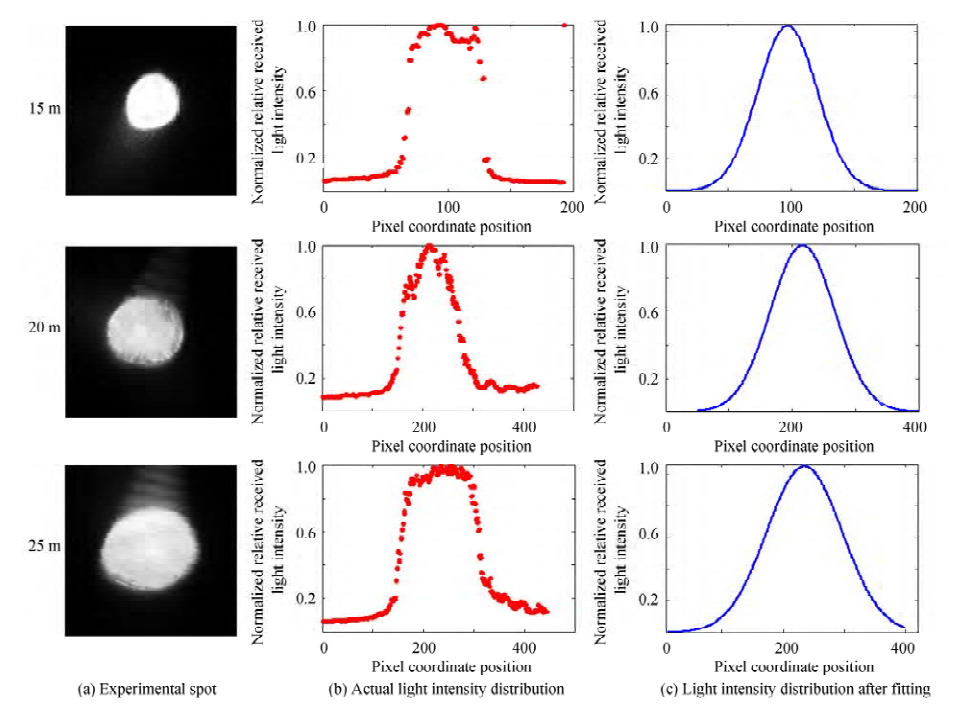
Figure 11. Spot detection experiment system [17]
This shows that even after long-distance underwater propagation, the light intensity at the receiving end of the Gaussian laser beam is still roughly Gaussian distributed, and the estimation method based on EKF has high accuracy for the underwater laser communication system. After alignment, the receiving end's efficiency in long-distance underwater laser communication can approach 98%, but if the receiving end is not aligned, it will result in significant intensity errors [17].
3.3.2. Receiver detector. The detectors commonly used at the receiver are PIN (positive-intrinsic-ne-gative) photodiode, avalanche photodiode (avalanche photon diode, APD), and photomultiplier (photomultiplier tube, PMT) [9]. The performance comparison of the three detectors are shown in Table 1.
Table 2. The comparison of detector performance [9].
Parameter | PIN | APD | PMT |
Sensitivity | Low | Moderate | High |
Detector area | Small | Small | Large |
Response speed | Slow | Fast | Super fast |
Volume | Small | Small | Large |
Security | Good | Good | Fragile |
Equivalent noise efficiency | High | Low | Super low |
Use-cost | Low | Moderate | High |
Since PIN lacks internal gain, an RF amplifier is used to further amplify the signal after comparing and evaluating the detector performance in Table 5. Using the avalanche breakdown effect, APD have a much greater detection sensitivity than PIN photodiodes [17]. In addition, they clearly outperform PIN in terms of reaction time and noise power [17]. The small detection areas of both, however, necessitate a greater link alignment of the UWOC system [17]. Because they can detect independent photons and do not require a span resistance amplifier to amplify the electrical signal, APD-single photon avalanche diodes (SPAD) operating in Geiger mode are ideal for long distance and low power underwater communications systems [19].
4. Conclusion
Due to the 5G technology's business strategy and the quick advancement of communication technology, the limited spectrum bandwidths are almost at capacity. The primary benefit of visible light over current technology is the spectrum's high degree of freedom and lack of regulatory restrictions. Although underwater communication is still a challenging issue to solve due to the amount of seawater and the scattering effect, underwater optical communication technology is a significant study area for 6G. Consequently, the significance and potential for growth of this paper.
References
[1]. Al-Zhrani, S. 2021, 10 26. Underwater Optical Communications: A Brief Overview And Recent Developments. Engineered Science, Pp. 146-186.
[2]. Liu, X. 2021. Impact Of Zooplankton On Underwater Wireless Optical Channel Transmission. International Conference On Microwave And Millimeter Wave Technology (ICMMT), (Pp. 1-3.
[3]. Duntley. 1963. Light In The Sea. Journal Of The Optical Society Of America, 07-14., G. 1966.
[4]. Zeng, F. 2021, 2. Research Progress In Underwater Laser Communication System. Advances In Laser And Optoelectronics, Pp. 1-12.
[5]. L. 2022, 8. Research And Prospect Of Underwater Optical Communication Technology. DIGITAL OCEAN & UNDERWATER WARFARE, Pp. 329-334.
[6]. Saeed, N. 2019. Underwater Optical Wireless Communications, Networking, And Localization: A Survey. Ad Hoc Networks, Pp. 1-35.
[7]. Oubei, H. M. 2015. 2.3 Gbit/S Underwater Wireless Optical Communications Using Directly Modulated 520 Nm Laser Diode. Optics Express, Pp. 20743-20748.
[8]. Wang, B. 2022, 1. Research Progress Of Underwater Wireless Optical Communication System. LASER TECHNOLOGY, Pp. 99-109
[9]. Wang, M. 2005, 02. Study On Optical Characteristics Of Seawater Channel For Blue-Green Laser Communication. Journal Of East China Shipbuilding Institute (Natural Science Edition), Pp. 59-62.
[10]. Qiong, W. 2021, 4. Analysis Of Underwater Wireless Optical Transmission Characteristics. ACTA PHOTONICA SINICA, Pp. 0406002-1~10.
[11]. Liang, H. 2021, 9. Research And Design Of Underwater Wireless Optical Research And Design Of Underwater Wireless Optical. Infrared And Laser Engineering, Pp. 20200445-1~9.
[12]. M. D. 2009. Quaoptical: A Lightweight Device For High-Rate Long-Range Underwater Point-To-Point Communication. Proceedings Of OCEANS 2009, Pp. 1-6.
[13]. ARVANITAKIS G N, B. R. 2020, 12. Underwater Wireless Optical Communications Using Series-Connected Gan Micro-LED Arrays. IEEE Photonics Journal, Pp. 1-10.
[14]. Wu, J. 2014, 5. Study And Implementation Of Underwater Wireless Optical Communication System.
[15]. Qingping, Y. 2018, 1. Research Of Channel Coding Techniques In 5G Communications. Exper Forum, Pp. 1-8.
[16]. Liu, H. 2020, 4. Alignment Control Alogorithm Of Underwater LD Communication Based On EKF. ACTA PHOTONICA SINICA, Pp. 1-9.
[17]. S. L. 2013, 4. Extended Kalman Filter For Channel Estimation In Raleigh Fading Environment And Fadingless Environment. International Journal Of Engineering Science, Pp. 621-627.
[18]. Chu, Y. 2015. Optical OFDM With Single-Photon Avalanche Diode[J]. IEEE Photonics Technology Letters, Pp. 943-946.
Cite this article
Wang,H. (2023). Channel characteristics of underwater optical communication system. Applied and Computational Engineering,12,135-144.
Data availability
The datasets used and/or analyzed during the current study will be available from the authors upon reasonable request.
Disclaimer/Publisher's Note
The statements, opinions and data contained in all publications are solely those of the individual author(s) and contributor(s) and not of EWA Publishing and/or the editor(s). EWA Publishing and/or the editor(s) disclaim responsibility for any injury to people or property resulting from any ideas, methods, instructions or products referred to in the content.
About volume
Volume title: Proceedings of the 2023 International Conference on Mechatronics and Smart Systems
© 2024 by the author(s). Licensee EWA Publishing, Oxford, UK. This article is an open access article distributed under the terms and
conditions of the Creative Commons Attribution (CC BY) license. Authors who
publish this series agree to the following terms:
1. Authors retain copyright and grant the series right of first publication with the work simultaneously licensed under a Creative Commons
Attribution License that allows others to share the work with an acknowledgment of the work's authorship and initial publication in this
series.
2. Authors are able to enter into separate, additional contractual arrangements for the non-exclusive distribution of the series's published
version of the work (e.g., post it to an institutional repository or publish it in a book), with an acknowledgment of its initial
publication in this series.
3. Authors are permitted and encouraged to post their work online (e.g., in institutional repositories or on their website) prior to and
during the submission process, as it can lead to productive exchanges, as well as earlier and greater citation of published work (See
Open access policy for details).
References
[1]. Al-Zhrani, S. 2021, 10 26. Underwater Optical Communications: A Brief Overview And Recent Developments. Engineered Science, Pp. 146-186.
[2]. Liu, X. 2021. Impact Of Zooplankton On Underwater Wireless Optical Channel Transmission. International Conference On Microwave And Millimeter Wave Technology (ICMMT), (Pp. 1-3.
[3]. Duntley. 1963. Light In The Sea. Journal Of The Optical Society Of America, 07-14., G. 1966.
[4]. Zeng, F. 2021, 2. Research Progress In Underwater Laser Communication System. Advances In Laser And Optoelectronics, Pp. 1-12.
[5]. L. 2022, 8. Research And Prospect Of Underwater Optical Communication Technology. DIGITAL OCEAN & UNDERWATER WARFARE, Pp. 329-334.
[6]. Saeed, N. 2019. Underwater Optical Wireless Communications, Networking, And Localization: A Survey. Ad Hoc Networks, Pp. 1-35.
[7]. Oubei, H. M. 2015. 2.3 Gbit/S Underwater Wireless Optical Communications Using Directly Modulated 520 Nm Laser Diode. Optics Express, Pp. 20743-20748.
[8]. Wang, B. 2022, 1. Research Progress Of Underwater Wireless Optical Communication System. LASER TECHNOLOGY, Pp. 99-109
[9]. Wang, M. 2005, 02. Study On Optical Characteristics Of Seawater Channel For Blue-Green Laser Communication. Journal Of East China Shipbuilding Institute (Natural Science Edition), Pp. 59-62.
[10]. Qiong, W. 2021, 4. Analysis Of Underwater Wireless Optical Transmission Characteristics. ACTA PHOTONICA SINICA, Pp. 0406002-1~10.
[11]. Liang, H. 2021, 9. Research And Design Of Underwater Wireless Optical Research And Design Of Underwater Wireless Optical. Infrared And Laser Engineering, Pp. 20200445-1~9.
[12]. M. D. 2009. Quaoptical: A Lightweight Device For High-Rate Long-Range Underwater Point-To-Point Communication. Proceedings Of OCEANS 2009, Pp. 1-6.
[13]. ARVANITAKIS G N, B. R. 2020, 12. Underwater Wireless Optical Communications Using Series-Connected Gan Micro-LED Arrays. IEEE Photonics Journal, Pp. 1-10.
[14]. Wu, J. 2014, 5. Study And Implementation Of Underwater Wireless Optical Communication System.
[15]. Qingping, Y. 2018, 1. Research Of Channel Coding Techniques In 5G Communications. Exper Forum, Pp. 1-8.
[16]. Liu, H. 2020, 4. Alignment Control Alogorithm Of Underwater LD Communication Based On EKF. ACTA PHOTONICA SINICA, Pp. 1-9.
[17]. S. L. 2013, 4. Extended Kalman Filter For Channel Estimation In Raleigh Fading Environment And Fadingless Environment. International Journal Of Engineering Science, Pp. 621-627.
[18]. Chu, Y. 2015. Optical OFDM With Single-Photon Avalanche Diode[J]. IEEE Photonics Technology Letters, Pp. 943-946.