


1. Introduction
Building Information Modeling (BIM) has played an important role in the field of modern architectural design and construction. BIM is an information sharing technology. Based on three dimensional (3D) architectural model design technology, it carries out statistics on various architectural, structural and electromechanical information of designed buildings. The building design information is then provided to the designer, builder and manager. In the construction process, compared with the previous plane construction drawings, BIM has more advantages. Firstly, plane drawings can only express plane information to the construction side, and the high degree and other details are easy to be lost. Secondly, the dimensions of the components of the plane drawings may be inconsistent, leading to the misunderstanding of the construction personnel. Finally, the revision of drawings cannot ensure the synchronization of information changes between the design and construction parties in time. This paper takes a school in Suzhou, China as a case to explore the specific application of BIM technology. The building model of BIM technology and the derived information collection software are used to analyze the application points of the project.
2. Project profile
The project is located in Suzhou, Jiangsu Province, China. The total area of the project is 47,815.84 m², and the construction area is 442,90 m². The building structure uses the frame structure which makes the integrity and stiffness of the structure better. At the same time can achieve better seismic effect. According to the nature of the building design service life of 50 years, the overall seismic fortification intensity is 7 degrees. Figure 1 is the overall overview of the project.
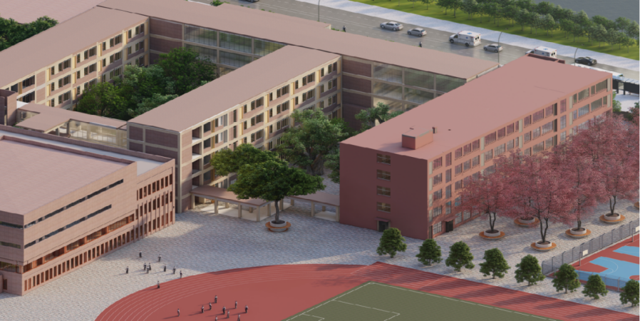
Figure 1. Project overview.
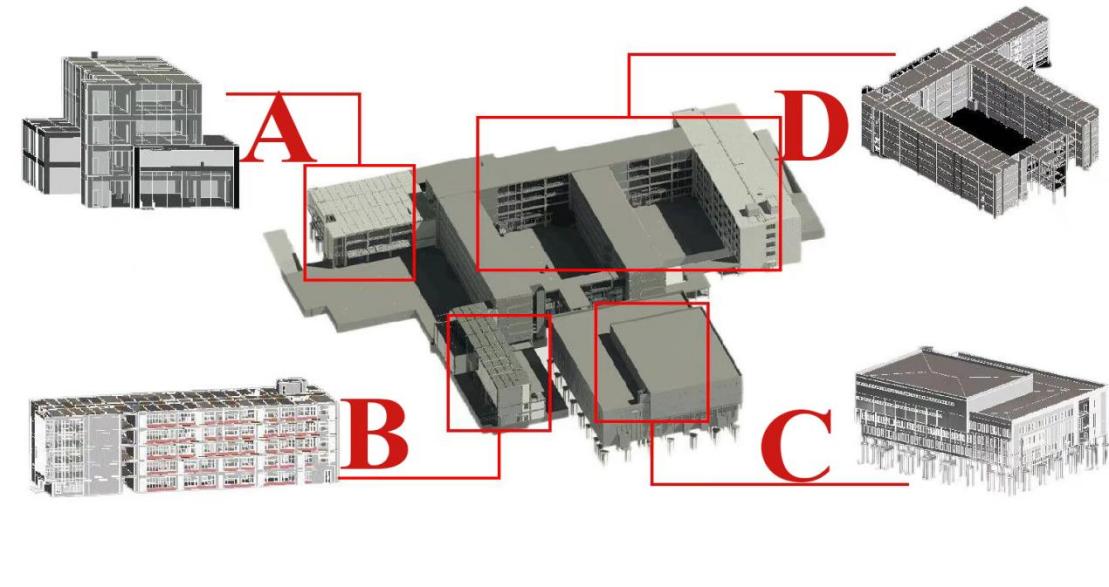
Figure 2. The exterior of the project.
Figure 2 is the exterior of the project and shows the four main parts of the building. Part A is a lecture hall library complex building. Compared with other buildings, this design adopts more framed curtain walls to ensure good lighting of the lecture hall on the second floor and the library on the first floor. Part B is the connecting corridor between the office building and the teaching building, which effectively ensures the relative comfort of the office environment. Part C is the dining hall and indoor gymnasium, which can meet students' indoor sports needs in rainy days. Part D is the main body of the teaching building. The front and back parts of the teaching building are connected by connecting corridors. This design can ensure the fluency of pedestrians in the teaching building, provide a variety of options for emergency evacuation and reduce the risk of stampede accidents.
3. Application analysis based on BIM technology
3.1. Forward design
Forward design and traditional reverse design are opposite concepts. In traditional design, it is usually the design unit that provides the graphic design drawing of the building, and then the modeling agency imports the graphic drawing into REVIT software to directly moulding according to the drawing, and finally exports the 3D information model. Forward design is a design method based on the client's specific needs and design concepts, and carries out specific design according to the client's requirements on the use and appearance of the building. Compared with traditional moulding, forward design pays more attention to customer needs and experience. It directly designs from 3D models to parameterize each part of the building and finally derives the plane drawing information, which is more accurate than traditional plane design and delivers more intuitive and accurate information to the construction side.
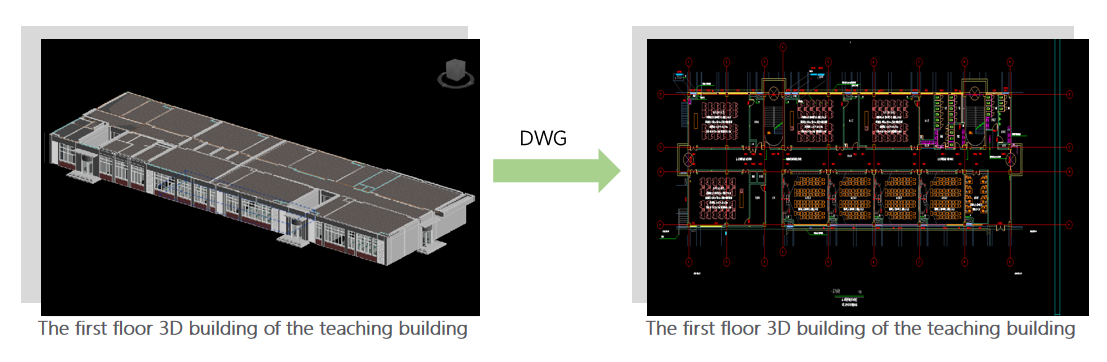
Figure 3. Forward design.
Forward design makes the process of drawing recognition more accurate and intuitive for construction personnel. 3D design is carried out in advance according to the client's design requirements and modeling requirements through 3D design software. Finally, the plan, elevation and section of the building are generated through the software. This clearly conveys the specific parameters of each part of the building. In some complex parts, 3D simulation can be carried out to ensure the construction process in one pass and reduce the problem of rework in the later stage. When the customer needs to change the design parameters, it can also be synchronized to each team of the project through the BIM platform.
The design environment of BIM forward design based on REVIT is 3D visualization. Compared with the abstract imagination based on projection in the planar architectural drawings, the spatial relations of all components in the forward design process are truly reflected, and the mutual influences among specialties are intuitively reflected in the model [1].
3.2. Family parameters
Component parameters is also known as family parameters. The definition of family refers to the basic elements used to represent building parts in REVIT software. parameters of family components refers to the transformation of the shape, size and material of the component into specific and changeable data information in the design stage, which can be used for data exchange between REVIT and other BIM software. In the concrete project, the parameters of the family can be modified according to the specific needs to meet the construction requirements. During the construction period, the variable of family parameterized parameters can be used to reduce the design work and design time, improve the efficiency of the construction team's drawing recognition, and speed up the construction process. REVIT has three types of families: system family, standard component family and built-in family [2].
(1) System family
System family refers to the pre-existing family components of the system in REVIT software, which mainly include mechanical, electrical and drainage systems. Mechanical system family mainly includes ventilation ducts, air conditioning equipment, water pumps, HVAC, etc. Electrical system family mainly includes cable bridge, current line tube. Electrical equipment, lighting equipment, etc. The drainage system family is mainly water supply and drainage pipes and sanitary equipment. A system family can only generate a new family type by specifying parameters. It cannot create a new family [3].
(2) Standard component family
The standard building family mainly refers to the components that are frequently used during design and construction. A standard build family is usually designed to be a standard size and then changes the size data at any time according to the design requirements. The standard component family mainly includes wall family, floor family, beam family, roof family and door and window family. It can be reused in different projects.
(3) Built-in family
A built-in family is a reusable artifact created by a designer. In the process of parameter change, all the same type family will update the parameters uniformly to ensure the consistency of the whole project. They apply only to specific objects of the project and have constraints that are larger than the standard family of components and smaller than the family of systems [3]. I In this project, the system family rapid construction structure model and electromechanical heating model (i.e., MEP model) are used in the structure and MEP part. According to different lighting requirements, the parameters of different types of doors and Windows are adjusted through a family of standard components.
3.3. Collision detection and optimization of pipeline system
In the design and modeling process of this project, the Mechanical, Electrical, and Plumbing model (i.e., MEP model) included many elements such as pipes, cables, Mechanical, Electrical, and Plumbing equipment and so on. In the process of modeling, it will be found that there are easy to cross, overlap and other problems between pipelines. In addition, the pipes will have space conflicts with other structural parts of the building. Therefore, LUBAN IWORK software is used for collision detection and report, which effectively optimized the model and analyzed the collision problems. This can greatly reduce the later construction error. In pipeline design, there are many kinds of pipes, so different colors of pipe parts are set to distinguish the functions of the pipes. When pipes cross, the principles to follow include thin pipes avoiding thick pipes, low pressure pipes avoiding high pressure pipes, and condensate pipes avoiding hot water pipes, so as to reduce the number of pipeline collisions [4].
Figure 4 shows the difference between before and after pipeline optimization. The optimization of pipeline collision area by LUBAN IWORK software ensures the accuracy of construction drawings, reduces unnecessary steps such as rework and redo in the later period, speeds up the construction schedule and reduces the construction cost. Figure 4 include before and after pipeline collision optimization.
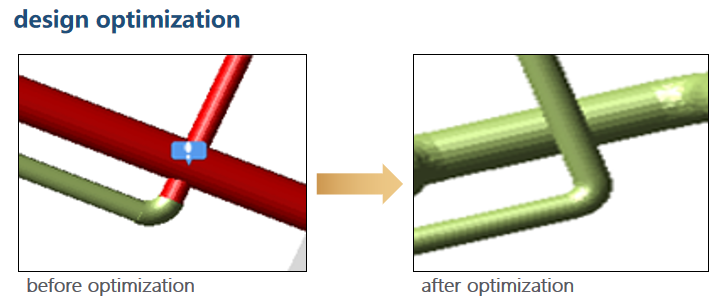
Figure 4. Clash detection.
In case of space overlap between pipeline system and building structure, conditions are set for hole reservation in LUBAN IWORK according to the hole reservation specification for water supply and drainage pipes and air ducts. Then the holes are inspected to avoid clogging, so as to improve the quality of construction. LUBAN IWORK can export reports of reserved holes, through which technicians can guide construction and reduce the cost of opening holes in the later stage of construction. Figure 5 is the hole reservation drawing, which shows that after the creation of the pipeline, through optimization, the pipeline openings are reserved, reducing the collision between the pipeline and the building part, and increasing the accuracy of the construction drawings. Figure 5 is a schematic diagram of opening reservation.
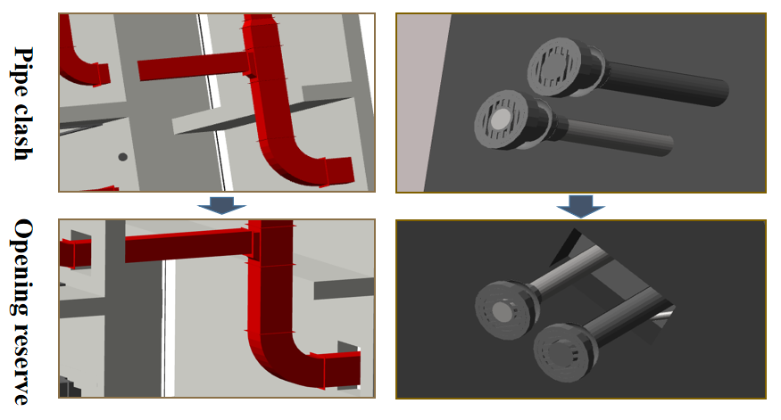
Figure 5. Opening reservation.
3.4. Application of BIM technology in the construction phase
3.4.1. Visual coordination. Visual Coordination is a technology that uses 3D simulation technology to show the environment simulation of project construction site. In the aspect of traditional BIM technology, when the building modeling is completed, there is a problem of single path of 3D model display, which is easy to cause the loss of architectural design information, resulting in certain errors between the actual building and the designed building [5]. Therefore, BIM FILM software and 3D virtual animation technology are adopted to solve the three main problems: the technical scheme cannot be refined, the model is not intuitive and the component information is not clear. The key and difficult parts of construction are visualized to present technical solutions. It is easier for the construction side to understand the architectural design details and design schemes, reduce the errors on the construction site, and avoid the rework caused by errors that slow down the construction process.
3.4.2. Construction progress simulation. Construction progress simulation is to provide visualized 4D simulation for construction personnel through the combination of construction simulation software and BIM model. In this way, it is convenient for the construction team and the architect to predict the problems that may be faced in the construction in advance so as to optimize the construction scheme, and at the same time, it can understand the construction process and details more intuitively. BIM visualization technology can realize the interactive discussion and dynamic of data information through the collection and integration of multi-source data [6].
In this project, by linking the model to the schedule, LUBAN IWORK software is used to make a visual model to accurately show the entire construction process. In this way, technicians can make construction plans and control construction progress in real time. The unified management and control of the construction progress, resources and quality of the project can shorten the construction period, reduce the cost and optimize the quality of the project. Figure 6 shows the construction schedule model generated by importing the construction plan into LUBAN IWORK software.
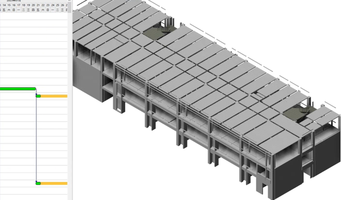
Figure 6. Construction progress simulation.
4. Analysis and exploration of green building application
With the development of domestic industry, environmental problems are becoming more and more serious. In order to cater to China's sustainable development strategy, the country vigorously promotes carbon neutrality strategy. In the construction industry, some people have put forward the concept of green building. Green building design is to transform the carbon emission and living environment in the whole life cycle of the building to ensure that the building design meets the national environmental protection requirements for buildings. Green building design is a design concept that takes function and environmental coordination as the foundation to realize the harmonious development between human and natural environment and takes ecosystem circulation as the basic principle [7].
4.1. Analysis of lighting environment
Lighting environment analysis means that designers use natural light to maximize the utilization rate of natural light inside the building, so as to reduce the dependence of the building on electric lights and reduce the overall energy consumption of the building. Compared with green building daylight analysis, traditional daylight analysis has two major contradictions. The first reason is that natural lighting effect is related to room depth, and the height and width of Windows need to be changed in the renovation process, but the height of the buildings limits the window specifications. Second, internal artificial lighting is not only related to the number of lamps but also to the arrangement of lamps, which cannot be determined by traditional analysis methods [8].
After the forward design, THSWARE software was used to analyze the lighting environment with building orientation, latitude, season and climate. If it is found that the lighting of the main function room is not up to standard, the indoor lighting can be improved by adding windows and skylights. If space is limited, window specifications and glass materials can be changed to improve the visible light projection ratio of windows to meet the lighting requirements of green buildings. During the first green analysis in this project, insufficient daylight and partial exposure were found in the inner areas of the building. The ratio of daylight coefficient to ground in some rooms does not meet the limit requirements. Therefore, the designers improved the lighting effect by adding more windows and changing the reflectivity of the glass. Figure 7 is a set of comparison charts of the lighting effect before and after the transformation drawn by the software.
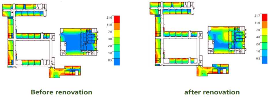
Figure 7. Daylight analysis diagram.
4.2. Thermal analysis
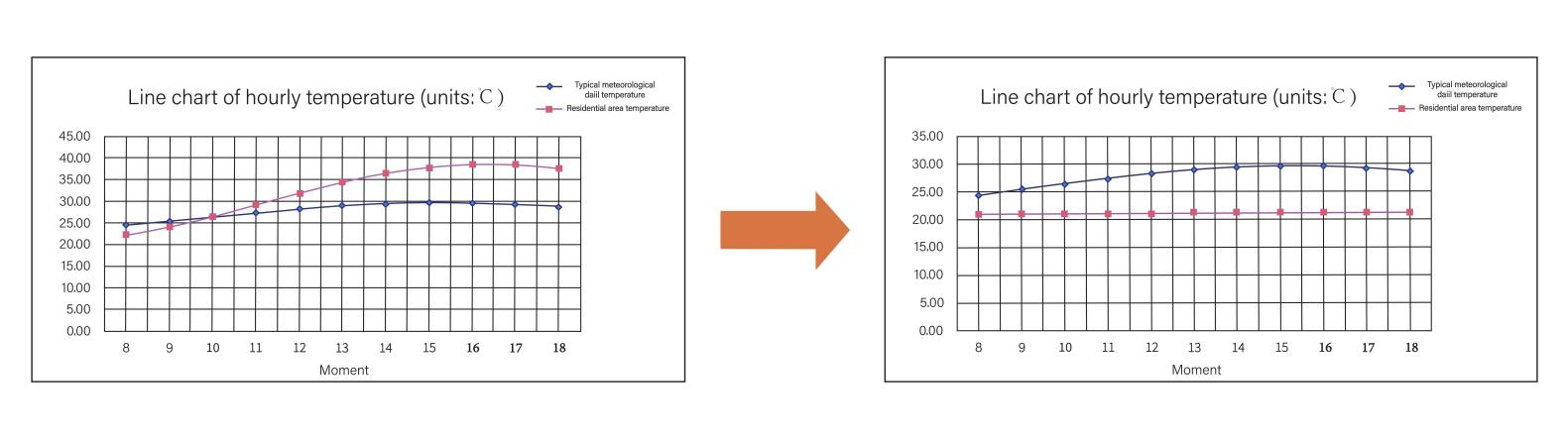
Thermal environment refers to the thermal environment of the building according to article of "Urban Residential Area Thermal Environment Design Standard" (JGJ 286-2013). When the evaluation design is carried out, the average summer heat island intensity of the residential area should not be greater than 1.5 ℃. In order make evaluation analysis, thermal environment analysis is usually related to heating surface, heat conduction and air convection. Meanwhile, the thermal environment analysis should also consider building orientation, exterior wall materials and other factors. Thermal environment analysis is aimed at improving the energy efficiency of buildings and improving the thermal comfort of residents. Finally, the thermal environment of the building is improved to reduce the carbon dioxide emission of the building.
Building thermal load is also a very important part of green building analysis, which will affect the building materials caused by temperature changes in the building structure deformation. Therefore, it is necessary to use light building materials such as polystyrene particle insulation cement for external walls according to the local climate. This can improve the external wall insulation performance and reduce the thermal load of the building [9-10].
Before the project transformation, the green belt around the school was less and the trees were sparse. This causes settling temperatures to be higher than typical local meteorological days for most of the day. Some measures were implemented, including changing the landscape around the school, increasing the green area, planting more dense trees in the green space, and arranging climbing trellis. The addition of green vegetation reduces the direct exposure of solar radiation to the building surface. Some heat is allowed to escape through the evaporation process of plant water, in order to ensure that the building residents have a good thermal comfort.
|
Figure 8. Temperature diurnal variation. |
4.3. Acoustic environment analysis
Acoustic environment analysis refers to the evaluation and analysis of the comfort inside the building according to the surrounding traffic, community type and whether there is an industrial zone and other factors. The first step in analyzing noise is to determine the level of noise through field measurements and then to determine the type of noise according to the source. Finally, the noise level of the building area would be reduced by setting up green belt and sound insulation envelope. According to China's National Environmental Noise Standard (GB 3096-2008), outside the school classroom, the maximum noise limit should not exceed 60 dB during the day (6:00-22:00) and 55 dB at night (22:00-6:00). In this project, the east and north sides of the building are close to the street, and the environmental noise exceeds the limit before the transformation, so the transformation is carried out by adding green belt and setting noise barrier. After the transformation, a compound noise barrier will be set up on the street side to reduce the peak value of environmental noise from 57 dB to 48 dB, meeting the requirements of the second type of noise limit. In addition, by improving the sound insulation performance of the outer door and window on the street side, and setting up a high sound insulation and sound absorption envelope between the teaching building and the office space, the noise level of the most unfavorable room in the room is reduced from 51 dB to 40 dB to meet the needs of students in class and office. Figure 9 is the comparison chart of acoustic environment effect before and after optimization.
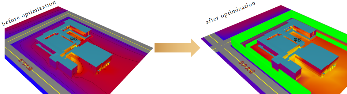
Figure 9. Acoustic environment optimization comparison diagram.
5. Conclusion
This paper takes a school as a building case and explores the application points of BIM technology from forward design, construction stage and green building analysis, so as to explore the application value of BIM technology in different stages. This study combines BIM technology to improve the traditional design method and the problems existing in the construction stage, and carries out the design transformation of the building living environment in the field of green building. In recent years, with the increasing proportion of BIM technology participating in actual projects, the visualization of BIM technology and the unity of information ensure the high coordination of various departments in construction management. BIM technology can be used to optimize the construction process and accurately manage the construction progress and cost according to the construction schedule. At the same time, it also reduces the error in the negotiation between the design party and the construction party, which reduces the number of repeated design and rework, thus improving the construction efficiency and reducing the construction cost. In terms of green building design, it can also transform the original design to create a more comfortable living environment and a higher utilization rate of natural energy, and reduce the carbon emissions of the building in the whole life cycle. In conclusion, strengthening BIM technology development can provide higher efficiency and lower cost to the construction industry, and satisfy the sustainable development strategy of our country. BIM technology has many advantages as it helps to better conserve energy, raw materials and water. It is one of the main directions of green building design in the future.
References
[1]. Ye A, Tao S, Zhu W, Wu Y, Hou J and Hu D 2023 Research on key points of forward design technology of structural BIM based on REVIT Zhejiang Constr. 40(02) pp 33-37.
[2]. Xiong W. 2017 Application research of superimposed slab shear wall structure based on BIM (Anhui Jianzhu University).
[3]. Cui K 2021 Research on Parametric Design of reinforced concrete structural members based on BIM technology (Shenyang University of Chemical Technology).
[4]. Jia Z, Liu JM and Shi H 2022 Application analysis of BIM technology in comprehensive pipeline collision detection Anhui Architecture 29(11) pp 82-83+107.
[5]. Yang QS,Wei F and Zhang SQ 2022 Application of VR technology based on BIM in visualization disclosure.East China Science & Technology 01 pp 95-97.
[6]. Zhou YB,Wu Z,Feng JW,Zhang SP 2022 Four - dimensional visual construction simulation of building structure based on BIM technology Brick-Tile 12 pp 144-146+149.
[7]. He X 2022 Discussion on the application of green building design concept under the background of carbon neutrality Industrial Technology Innovation 5(01) pp 14-16.2023.
[8]. Xv L 2023 Application of BIM technology in green building design Green Build. 15(02) pp 13-17.
[9]. Tian LC 2022 Discussion on green building design based on BIM technology Create Living 05 pp 98-100.
[10]. Pan Z, Pan H, Xia Z, Tian Q, Pan L and Li H 2023 Cost management analysis of a green building project based on BIM technology application Intell. Build. Smart City 03 pp 102-105.
Cite this article
Huang,Q. (2023). Research on building design and construction application based on BIM technology. Applied and Computational Engineering,24,66-74.
Data availability
The datasets used and/or analyzed during the current study will be available from the authors upon reasonable request.
Disclaimer/Publisher's Note
The statements, opinions and data contained in all publications are solely those of the individual author(s) and contributor(s) and not of EWA Publishing and/or the editor(s). EWA Publishing and/or the editor(s) disclaim responsibility for any injury to people or property resulting from any ideas, methods, instructions or products referred to in the content.
About volume
Volume title: Proceedings of the 2023 International Conference on Functional Materials and Civil Engineering
© 2024 by the author(s). Licensee EWA Publishing, Oxford, UK. This article is an open access article distributed under the terms and
conditions of the Creative Commons Attribution (CC BY) license. Authors who
publish this series agree to the following terms:
1. Authors retain copyright and grant the series right of first publication with the work simultaneously licensed under a Creative Commons
Attribution License that allows others to share the work with an acknowledgment of the work's authorship and initial publication in this
series.
2. Authors are able to enter into separate, additional contractual arrangements for the non-exclusive distribution of the series's published
version of the work (e.g., post it to an institutional repository or publish it in a book), with an acknowledgment of its initial
publication in this series.
3. Authors are permitted and encouraged to post their work online (e.g., in institutional repositories or on their website) prior to and
during the submission process, as it can lead to productive exchanges, as well as earlier and greater citation of published work (See
Open access policy for details).
References
[1]. Ye A, Tao S, Zhu W, Wu Y, Hou J and Hu D 2023 Research on key points of forward design technology of structural BIM based on REVIT Zhejiang Constr. 40(02) pp 33-37.
[2]. Xiong W. 2017 Application research of superimposed slab shear wall structure based on BIM (Anhui Jianzhu University).
[3]. Cui K 2021 Research on Parametric Design of reinforced concrete structural members based on BIM technology (Shenyang University of Chemical Technology).
[4]. Jia Z, Liu JM and Shi H 2022 Application analysis of BIM technology in comprehensive pipeline collision detection Anhui Architecture 29(11) pp 82-83+107.
[5]. Yang QS,Wei F and Zhang SQ 2022 Application of VR technology based on BIM in visualization disclosure.East China Science & Technology 01 pp 95-97.
[6]. Zhou YB,Wu Z,Feng JW,Zhang SP 2022 Four - dimensional visual construction simulation of building structure based on BIM technology Brick-Tile 12 pp 144-146+149.
[7]. He X 2022 Discussion on the application of green building design concept under the background of carbon neutrality Industrial Technology Innovation 5(01) pp 14-16.2023.
[8]. Xv L 2023 Application of BIM technology in green building design Green Build. 15(02) pp 13-17.
[9]. Tian LC 2022 Discussion on green building design based on BIM technology Create Living 05 pp 98-100.
[10]. Pan Z, Pan H, Xia Z, Tian Q, Pan L and Li H 2023 Cost management analysis of a green building project based on BIM technology application Intell. Build. Smart City 03 pp 102-105.