


1. Introduction
1.1. Structural health monitoring
The structural health monitoring system is to use sensors permanently installed on the structure to monitor the mechanical and physical condition of building in real time while undergoing routine operation, the working status of ancillary facilities, the durability of structural components and the environmental conditions of the engineering structure [1].
The aim of structural health monitoring is to achieve automatic, real-time, and continuous online monitoring of structural health status with minimal human intervention. This monitoring technique can evaluate the operational status of the structure and provide a reliable basis for its maintenance and management decisions.
Firstly, structures can be monitored by this technique in real-time which means a more effective cost for damage detection and maintenance. Then, it can record historical data objectively and reduce human factors. So subjective errors can be reduced. Meanwhile, downtime is reduced and reliability is increased by this technique. This can ensure an efficient operation of engineering structure and a significantly reduction of operating costs [1].
1.2. Smart materials in structural health monitoring
Intelligent materials refer to materials that can perceive changes in environmental conditions or internal states, automatically make timely, sensitive, and appropriate responses, and have functions including self-diagnosis, self-regulation, and self-healing [1]. Intelligent material systems can be divided into two categories based on their functional characteristics [2]. One type is materials that have sensing functions for external or internal stimuli such as stress, strain, and light, heat, electricity, magnetism, radiation, etc., commonly known as sensing materials. Another type is materials that can respond or drive changes in external environmental conditions or internal states. Commonly used piezoelectric materials, shape memory materials, and magneto strictive materials are both driving and sensing materials.
1.3. Techniques using piezoelectric transducers
At present, Piezoelectric transducers are primarily used in the disciplines of intelligent vibration management of structures, damage diagnostics, and health monitoring in civil engineering [3-6]. The working principle is that piezoelectric materials have both positive and negative piezoelectric effects. When a piezoelectric material is deformed by an external force that is applied in the polarization direction, opposite polarity charges are created on the lower and upper surfaces of the material, which is referred to as the positive piezoelectric effect. Conversely, deformation occurs when an electric field is generated in the direction of polarization, which is known as the inverse piezoelectric effect [7]. Piezoelectric materials have both sensing and driving functions. By utilizing the positive piezoelectric effect, mechanical energy of piezoelectric materials is converted into electrical energy which can be made into sensing elements [8]. By utilizing the inverse piezoelectric effect, electrical energy produced by the external electric field on the surface of piezoelectric materials can be generated to mechanical energy which can be made into driving components [8]. Piezoelectric materials can be roughly categorized into piezoelectric crystals, piezoelectric ceramics, organic piezoelectric materials and piezoelectric composite materials [9]. Among these piezoelectric materials, PZT is widely used due to its high piezoelectric coefficient and stable piezoelectric performance [10].
The structural monitoring technology using piezoelectric materials can be separated into two methods: active monitoring, including piezoresistive impedance method and fluctuation analysis method, and passive monitoring.
1.3.1. Impedance analysis method. When a structure is in a certain condition, its mechanical impedance remains constant. If the state of the structure changes (such as damage), its mechanical impedance will also change accordingly. Therefore, the monitoring of structural health status can be achieved by measuring the mechanical impedance value of the structure to investigate whether there is damage to the structure [11]. However, it is challenging to accurately quantify the structure's mechanical impedance value. Hence, the structure's mechanical impedance might be measured indirectly by measuring the impedance of the piezoelectric sheet connected to the structure surface. Applying an AC electric field to the piezoelectric sheet pasted on the surface of the structure will generate mechanical vibration and drive the main structure to vibrate because of inverse piezoelectric effect. The mechanical vibration of the body structure reacts on the piezoelectric sheet then an electrical response can be generated because of the positive piezoelectric effect, manifested as changes in electrical impedance. Information concerning the status of structural damage is contained in the piezoelectric material's electrical impedance signal. The condition of the structure's damage may be determined by comparing the electrical impedance signal to that of the structure without faults [12].
This method has many advantages. Firstly, the operating frequency used is relatively high, usually between 30kHz and 500kHz. Thus, the range of its sensitivity is constrained to the vicinity of the piezoelectric element. This may isolate the impact of far-field factors like load, stiffness, and boundary conditions. The high-frequency characteristics also make the impedance method more sensitive to small damages. Besides, a piezoelectric chip is both a driver and a sensor. The idea of self-sensing and self-driving is applied to decrease the amount of instruments and equipment used in structural health monitoring. Meanwhile, by utilizing the characteristic that the distance between the damage and the piezoelectric element has a significant impact on the electrical admittance value of the piezoelectric element, arranging a sensor network on the surface of a large structure can effectively identify the location of the damage.
However, the effective response range of sensors is small, and for damage monitoring of large volume structures, many sensors need to be arranged. When using the piezoelectric impedance method for structural damage detection, piezoelectric sheets are often affixed to the surface of the structure. If the detected structure is a large volume structure, it is difficult for piezoelectric sheets to detect damage inside the structure. In addition, the adhesion of piezoelectric ceramic sheets to the surface of the structure is easily affected by the environment, resulting in significant errors in the measurement results.
1.3.2. Stress wave analysis method. By attaching piezoelectric sensors to the surface of the structure or embedding them inside the structure, a piezoelectric intelligent structural system is formed between the piezoelectric sensor and the monitored structure. One piezoelectric sensor emits stress waves and the other receives them. Identify damage and defects in the structure by analyzing the differences in signals received by sensors before and after the structure [13].
Compared with impedance analysis method, Stress wave analysis method has some advantages. One of the advantages of this method is that the detection area is large. For the structural health monitoring method based on the piezoelectric wave method, the piezoelectric sensor is usually embedded inside the structure, and the frequency of the external excitation is lower than that of the impedance method, so the stress wave can travel farther in the structure. In addition, Multiple types of excitation signals can be selected for health monitoring, such as pulse waves, sweep waves, etc. There are also many characteristic parameters used for analyzing damage, such as signal amplitude, phase. Especially, this method is suitable for health monitoring of concrete structures. Because piezoelectric ceramic sheets can be embedded inside concrete, this can to some extent reduce the interference of the sensor from the external environment and ensure the service life of the sensor [1]. But the noise interference should be considered when applying the method as the signal is susceptible it which may cause a great error in monitoring.
1.3.3. Passive monitoring. This method uses sensors directly to monitor structure’s real-time status and determine the structure’s health status based on the monitoring parameter characteristics, combined with mechanical modeling analysis, prior knowledge, and relevant instruments such as acoustic emission meters. This technique is used frequently in structural deformation monitoring under environmental load and impact load monitoring. It is not suitable for measuring physical quantities with low frequencies and measuring static quantities.
1.4. What we did in this study
Through the above introduction, it is obvious that piezoelectric transducers have great potential in infrastructure health monitoring, especially pavement monitoring. In the present study, the impedance characteristics of a piezoelectric plate embedded in the pavement is utilized to monitor the health status of the pavement. An electromechanical model of a piezoelectric plate embedded in the pavement is established using the piezoelectricity theory. The damage of the pavement is considered as the thickness decreasing of the pavement layer. This study primarily presents the theoretical basis of pavement monitoring using electromechanical impedance of piezoelectric plates. The remainder of the paper is organized as follows. In section 2, a piezoelectric plate embedded in the pavement is established as an electromechanical model based on the piezoelectricity theory. Electrical and mechanical component expressions in every layer are generated. The electrical and mechanical boundary and continuous conditions are utilized to summarize and solve the unknown constants included in the formulas. In section 3, the electrical and mechanical boundary conditions of a single layer piezoelectric actuator are summarized. The degenerated numerical result is compared with exact theoretical result. In section 4, numerical discussions are created to illustrate how decreasing pavement thickness affects admittance, conductance, and impedance of the embedded piezoelectric plate. Section 6 concludes the study.
2. Theoretical modeling
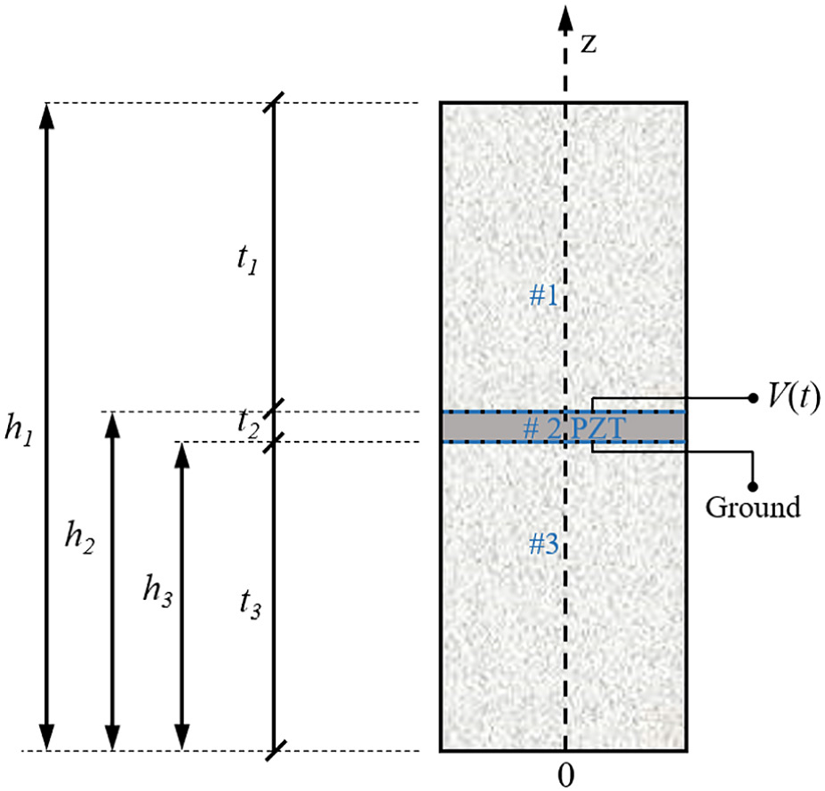
Figure 1. Schematic of a piezoelectric plate embedded in the pavement.
Figure 1 illustrates the electromechanical model of a piezoelectric plate embedded in pavement [14]. The piezoelectric layer in layer 2 is thought to be sandwiched between two elastic layers, i.e., layer 1 and layer 3, which are considered as the pavement. Note that polarization of layer 2 is in the +z direction. The thickness of layer 1-3 are t1-t3, respectively. The coordinate of the interfaces are h2 and h3, and the surface coordinate are 0 and h1. Additionally, the system's cross-sectional area is thought of as a. As illustrated in Figure 1, the upper surface of the piezoelectric layer is exposed to an external voltage of V(t), while the piezoelectric layer's bottom surface is grounded. Using the external voltage and the calculated input electric current, the input impedance of the model could be obtained.
2.1 Derivation based on E-type constitutive equations
The piezoelectric layer’s constitutive equations might be expressed as follows without taking body force and body charge into account [15].
\( {T_{Z}}=c_{33}^{E}{S_{Z}}-{e_{33}}{E_{Z}} \) (1)
\( {D_{z}}={e_{33}}{S_{z}}+ε_{33}^{S}{E_{z}} \) (2)
where Tz and Sz presents the piezoelectric layer's stress and strain components in the z direction, respectively. Electric displacement and electric field intensity along the z direction are shown, respectively, by the letters Dz and Ez. \( c_{33}^{E} \) is elastic constant. e33 is the piezoelectric constant while \( ε_{33}^{S} \) is the dielectric constant. A parameter at constant electric field and strain, respectively, are denoted by the superscripts E and S. The superscripts are removed for convenience in the following.
The piezoelectric layer's geometric relationship equations might be expressed as [16].
\( {S_{z}}=\frac{∂w}{∂z} \) (3)
\( {E_{z}}=-\frac{∂ϕ}{∂z} \) (4)
where w is the piezoelectric layer's displacement in the z direction while ϕ presents the electric potential.
The piezoelectric layer's dynamic and electric displacement equilibrium equations might be expressed as
 (5)
(5)
 (6)
(6)
where ρ is the piezoelectric layer's density.
If the input voltage V(t) is of the following harmonic form
 (7)
(7)
where Vin is the voltage amplitude, \( j=\sqrt[]{-1} \) , f is the input signal frequency and \( ω=2πf \) is the circular frequency. The formulae for the stress, electric displacement, electric potential, and displacement of the piezoelectric layer in steady state might be expressed as
 (8)
(8)
Substituting Equation (3) and (4) into Equation (1) yields
 (9)
(9)
Substituting Equation (4) and (6) into Equation (2) yields
 (10)
(10)
Combine Equation (9) and (10), we have
 (11)
(11)
Substituting Equation (11) into Equation (5) yields
 (12)
(12)
Substituting Equation (10) into Equation (12) yields
 (13)
(13)
where 
Solve Equation (13), we have
 (14)
(14)
where A and B are unknown coefficients.
Combine Equation (14) with Equation (10), we have
 (15)
(15)
where  , C1 and C0 are unknown coefficients.
Consequently, the piezoelectric layer's stress component can be represented as
 (16)
(16)
where 

The piezoelectric layer's electric displacement can be represented as
 (17)
(17)
Till now, the expressions of the stress, the electric displacement, the electric potential and the displacement of the piezoelectric layer have been determined with the unknown constants are A, B, C0, and C1.
For the elastic layer, matching stress and displacement formulas for the elastic layer may be created by replacing e33=0. A and B represent the two unknown constants.
A subscript is introduced to the current research to separate material properties and unknown coefficients in various layers. Figure 1 depicts a piezoelectric layer and two elastic layers. The eight unknown constants are denoted as
 (18)
(18)
where the layer number is indicated by the last subscript number. The boundary and continuous conditions can be used to determine all the unknown coefficients.
2.2 Boundary and continuous conditions for a piezoelectric plate sandwiched by two elastic layers
The following lists, in order, outline the mechanical continuous conditions, the mechanical boundary conditions, and the electrical boundary conditions. Note that the layer number is represented by the last digit of the component subscript.
The piezoelectric layer's electrical boundary conditions (layer 2) are as follows:
 (19)
(19)
Mechanical boundary conditions:
 (20)
(20)
Mechanical continuous conditions
 (21)
(21)
The eight algebra equations generated by the boundary and continuous conditions could be summarized as
 (22)
(22)
Which could be transferred to coefficient matrix form as
 (23)
(23)
The eight unknown coefficients can be obtained using the eight algebra equations generated from the electrical and mechanical boundary conditions.
The input electric current amplitude can be defined as
 (24)
(24)
The input impedance and admittance may be calculated respectively as
 (25)
(25)
3. Model validation
3.1. Boundary conditions for single layer actuator model
The electrical and mechanical boundary conditions of a single layer piezoelectric actuator are summarized as follows, respectively.
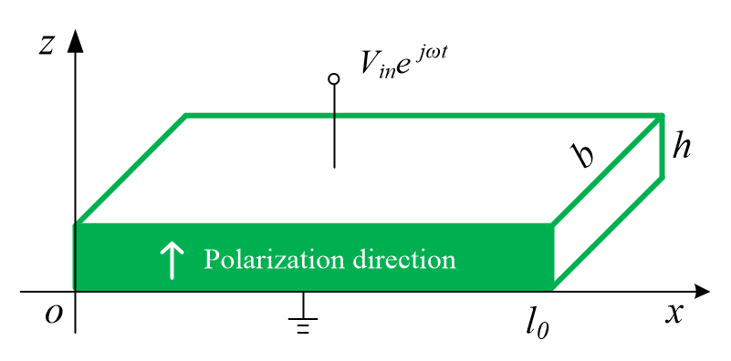
Figure 2. Schematic of a single layer piezoelectric actuator.
The piezoelectric transducer's electrical boundary conditions:
 (26)
(26)
Mechanical boundary conditions:
 (27)
(27)
To solve the algebra equations obtained, the mechanical and electrical boundary conditions are used for the unknown coefficients:
 (28)
(28)
The four unknown coefficients could be solved as
 (29)
(29)
The input electric current amplitude can be defined as
 (30)
(30)
The input impedance and admittance may be respectively calculated as
 (31)
(31)
3.2. Comparison between degenerated numerical result and exact theoretical result
In this section, to verify the impedance analysis model of the three-layer piezoelectric composites presented in this study, the three-layer model is degenerated and compared with a single layer model. Material parameters of the pavement layer are taken from the Youhao South Road in Xinjiang [17]. By taking \( {t_{1}}=0 mm, {t_{2}}=1 mm, {t_{3}}=0 mm, \) a single layer is created by downsizing the present three-layer model. The parameters of e-type piezoelectric material and elastic material are provided in tables 1 and 2 respectively. The stiffness constant \( {c_{33}} \) is substituted by \( {c_{33}}(1+{Q^{-1}}j) \) when considering the damping effect, where Q represents the damping factor. Typically, ceramics have a damping between \( {10^{2}} \) and \( {10^{3}} \) . In the study, Q is considered as \( {10^{2}} \) for both the piezoelectric and elastic material. To verify the research, the input impedance’s frequency response obtained in the degeneration of three-layer piezoelectric composites are compared with that obtained in single layer model respectively in Figures 3. As illustrated in Figures 3, the results match well.
Table 1. Parameters of the piezoelectric layer's (e-type) materials [14].
Density | Stiffness constant \( c_{33}^{E} \) | Piezoelectric constant \( {e_{33}} \) | Dielectric constant \( ε_{33}^{S} \) |
\( 7.5×{10^{3}}kg{m^{-3}} \) | \( 11.7×{10^{10}}N{m^{-2}} \) | \( 23.3C{m^{-2}} \) | \( 1470{ε_{0}} \) |
\( Note.{ε_{0}}=8.854×{10^{-12}}farads {m^{-1}} \) .
Table 2. Parameters and geometric dimensions of pavement’s material [9].
Pavement structural layer | Material | Depth(cm) | Elastic modulus(MPa) | Poisson’s ratio | Density(t/m3) |
Substrate | Medium grained asphalt concrete | 4 | 1300 | 0.35 | 2.43 |
Subsurface | Coarse grained asphalt concrete | 6 | 1200 | 0.35 | 2.45 |
Basic level | Cement stabilized gravel | 15 | 1500 | 0.30 | --- |
Subbase layer | Natural gravel | 245 | 60 | 0.40 | --- |
4. Results and discussion
In this section, the numerical studies are produced without taking the bonding effect, thermal effect, dielectric and piezoelectric losses into account. Damage to pavement's consequences is considered as the thickness decreasing of layer 1, i.e., \( { t_{1}} \) . The fixed geometric parameters are \( { t_{2}}=1 mm, {t_{3}}=60 mm \) . Utilizing the material properties mentioned in tables 1 and 2. When considering the damping effect, substituting the stiffness constant \( {c_{33}} \) by \( {c_{33}}(1+{Q^{-1}}j) \) , where Q is the damping factor which is generally between \( {10^{2}} \) and \( {10^{3}} \) . In the study, Q is considered as \( {10^{2}} \) for both the piezoelectric and elastic material.
To investigate the effect of pavement damage on the electromechanical impedance of the embedded piezoelectric plate, different values of layer 1 thickness \( {t_{1}} \) are applied. With \( {t_{1}} \) respectively being 40, 20, 10 and 0 mm, demonstrating the deterioration of the pavement, frequency response of impedance, admittance and conductance is conducted. Results are presented as follows.
Figure 4 illustrates the embedded piezoelectric plates’ impedance frequency response for different layer 1 thickness i.e., different deterioration level. Through figure 4, with the increase of frequency between \( 2×{10^{6}} and 2.5×{10^{6}} \) Hz, all the impedance increase to the peak and then drop. For different layer 1 thickness, the achievable maximum impedance decreases with the increasing of the pavement thickness. Meanwhile, with the increase of layer 1 thickness, a smoother curve appears. When \( {t_{1}}=0, \) the curve is smooth as well.
Figure 5 shows the frequency response of admittance for various pavement thickness. Through Figure 5, the achievable maximum admittance is at around \( 2×{10^{6}} Hz. \) With the increase of frequency between \( 2×{10^{6}} and 2.4×{10^{6}} \) Hz, all the admittance decreases and then increases after \( 2.4×{10^{6}} \) Hz. For different pavement thickness, the achievable maximum admittance decreases with the increase of pavement thickness. Meanwhile, with the increase of pavement thickness, a smoother curve appears. When \( {t_{1}}=0, \) the curve is smooth as well.
Figure 6 illustrates the frequency response of conductance for different pavement thickness. Through Figure 6, the achievable maximum conductance is at around \( 2×{10^{6}} Hz. \) The graph is symmetrical and the conductance decreases with the increase of frequency after \( 2×{10^{6}} Hz \) For different pavement thickness, the achievable maximum admittance decreases with the increase of pavement thickness. Meanwhile, with the increase of pavement thickness, a smoother curve appears. When \( {t_{1}}=0, \) the curve is smooth as well.
The results presented above shows that the achievable maximum impedance, admittance and conductance of the embedded piezoelectric plate could be utilized as the indicator of pavement damage level.
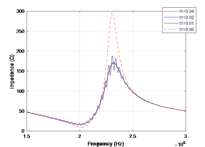
Figure 4. Frequency response of the impedance of the embedded piezoelectric plate with respect to the remaining pavement thickness.
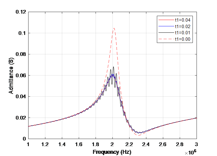
Figure 5. Frequency response of the admittance of the embedded piezoelectric plate with respect to the remaining pavement thickness.
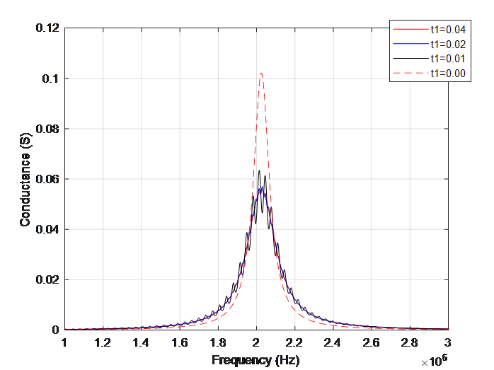
Figure 6. Frequency response of the conductance of the embedded piezoelectric plate with respect to the remaining pavement thickness.
5. Conclusion
In the present study, the impedance characteristics of a piezoelectric plate embedded in the pavement is utilized to monitor the health status of the pavement. An electromechanical model of a piezoelectric plate embedded in the pavement is established on the basis of the theory of piezoelectricity. The damage of the pavement is considered as the thickness decreasing of the pavement layer. The present proposed model is verified by comparing its degeneration with a single layer model. Numerical results demonstrated that with the deceasing of the thickness of layer 1, which is considered as the deterioration of the pavement, the achievable maximum electromechanical impedance characterization including impedance, admittance and conductance decreased. This phenomenon demonstrated that the achievable maximum impedance, admittance and conductance of an embedded piezoelectric plate could be used as the indicator of pavement health monitoring.
References
[1]. Sun W 2009 Intelligent concrete Structural health monitoring technology using piezoelectric ceramics (Dalian University of Technology
[2]. Yang Q 1999 Research and Development of Intelligent Materials. Functional Materials (6): 575-581
[3]. Yan S, Zhang H 2008 Numerical analysis and control for cantilever flexible beams using PZT patches. International Society for Optics and Photonics. International Society for Optics and Photonics
[4]. Yan S and Zhang H 2008 Experimental study on positive feedback control of flexible cantilever beams using piezoelectric ceramic actuators. Journal of Shenyang Jianzhu University, 24 (3): 362-365
[5]. Wu K 2003 Theoretical and Experimental Research on Active Vibration Control of Intelligent Composite Structures Embedded in Piezoelectric Materials (Doctoral dispersion, Northwestern Polytechnical University)
[6]. Wu K 2003 Theoretical and Experimental Research on Active Vibration Control of Intelligent Composite Structures Embedded in Piezoelectric Materials (Doctoral dispersion, Northwestern Polytechnical University)
[7]. Zhang H 2016 Piezoelectric aggregate stress monitoring and model correction for seismic damage of reinforced concrete structures (Dalian University of Technology)
[8]. Zhang X 2021 Research on Structural health monitoring using piezoresistive impedance method based on adjustable inductance (Southeast University)
[9]. Hu X 2018 Research on Damage Identification of Plate Structures Based on Piezoelectric Impedance Technology (Doctoral Dissertation, Huazhong University of Science and Technology)
[10]. Cao P, Shuai Q and Tang J 2017 Structural damage identification using piezoelectric impedance measurement with sparse inverse analysis. Smart Materials & Structures
[11]. Jiao L and Li H 2006 Research progress of PZT's EMI technology in civil engineering health monitoring. Journal of Disaster Prevention and Reduction Engineering, 26 (1), 102-108
[12]. Park G, Cudney H, et al 2000 Impedance-based health monitoring of civil structural components. Journal of Infrastructure Systems, 6(4): 153-160
[13]. Sun M, Li Z and Hou Z 2003 Application of piezoelectric materials in Structural health monitoring of civil engineering. Concrete, 161 (3): 22-24
[14]. Zhang C, Wang X, Yan Q, et al 2020 A novel method to monitor soft soil strength development in artificial ground freezing projects based on electromechanical impedance technique: Theoretical modeling and experimental validation. Journal of Intelligent Material Systems and Structures, 31(12): 1477-1494
[15]. Hu Y, Zhang X, et al 2003 Transmitting electric energy through a metal wall by acoustic waves using piezoelectric transducers. IEEE Transactions on Ultrasonics Ferroelectrics and Frequency Control, 50(7): 773-781
[16]. Wang X, Shi Z and Song G. 2018 Analytical study of influence of boundary conditions on acoustic power transfer through an elastic barrier. Smart Materials and ltructures, 28
[17]. Ji H 2021 Research on the Mechanism of Asphalt Pavement Defects in BRT Special Lane of Urban Roads in Seasonal Frozen Areas of Xinjiang Based on Finite Element ANSYS Analysis. (Xinjiang Agricultural University)
Cite this article
Zhang,C. (2023). Pavement damage monitoring using electromechanical impedance of embedded piezoelectric plate. Applied and Computational Engineering,25,30-42.
Data availability
The datasets used and/or analyzed during the current study will be available from the authors upon reasonable request.
Disclaimer/Publisher's Note
The statements, opinions and data contained in all publications are solely those of the individual author(s) and contributor(s) and not of EWA Publishing and/or the editor(s). EWA Publishing and/or the editor(s) disclaim responsibility for any injury to people or property resulting from any ideas, methods, instructions or products referred to in the content.
About volume
Volume title: Proceedings of the 2023 International Conference on Functional Materials and Civil Engineering
© 2024 by the author(s). Licensee EWA Publishing, Oxford, UK. This article is an open access article distributed under the terms and
conditions of the Creative Commons Attribution (CC BY) license. Authors who
publish this series agree to the following terms:
1. Authors retain copyright and grant the series right of first publication with the work simultaneously licensed under a Creative Commons
Attribution License that allows others to share the work with an acknowledgment of the work's authorship and initial publication in this
series.
2. Authors are able to enter into separate, additional contractual arrangements for the non-exclusive distribution of the series's published
version of the work (e.g., post it to an institutional repository or publish it in a book), with an acknowledgment of its initial
publication in this series.
3. Authors are permitted and encouraged to post their work online (e.g., in institutional repositories or on their website) prior to and
during the submission process, as it can lead to productive exchanges, as well as earlier and greater citation of published work (See
Open access policy for details).
References
[1]. Sun W 2009 Intelligent concrete Structural health monitoring technology using piezoelectric ceramics (Dalian University of Technology
[2]. Yang Q 1999 Research and Development of Intelligent Materials. Functional Materials (6): 575-581
[3]. Yan S, Zhang H 2008 Numerical analysis and control for cantilever flexible beams using PZT patches. International Society for Optics and Photonics. International Society for Optics and Photonics
[4]. Yan S and Zhang H 2008 Experimental study on positive feedback control of flexible cantilever beams using piezoelectric ceramic actuators. Journal of Shenyang Jianzhu University, 24 (3): 362-365
[5]. Wu K 2003 Theoretical and Experimental Research on Active Vibration Control of Intelligent Composite Structures Embedded in Piezoelectric Materials (Doctoral dispersion, Northwestern Polytechnical University)
[6]. Wu K 2003 Theoretical and Experimental Research on Active Vibration Control of Intelligent Composite Structures Embedded in Piezoelectric Materials (Doctoral dispersion, Northwestern Polytechnical University)
[7]. Zhang H 2016 Piezoelectric aggregate stress monitoring and model correction for seismic damage of reinforced concrete structures (Dalian University of Technology)
[8]. Zhang X 2021 Research on Structural health monitoring using piezoresistive impedance method based on adjustable inductance (Southeast University)
[9]. Hu X 2018 Research on Damage Identification of Plate Structures Based on Piezoelectric Impedance Technology (Doctoral Dissertation, Huazhong University of Science and Technology)
[10]. Cao P, Shuai Q and Tang J 2017 Structural damage identification using piezoelectric impedance measurement with sparse inverse analysis. Smart Materials & Structures
[11]. Jiao L and Li H 2006 Research progress of PZT's EMI technology in civil engineering health monitoring. Journal of Disaster Prevention and Reduction Engineering, 26 (1), 102-108
[12]. Park G, Cudney H, et al 2000 Impedance-based health monitoring of civil structural components. Journal of Infrastructure Systems, 6(4): 153-160
[13]. Sun M, Li Z and Hou Z 2003 Application of piezoelectric materials in Structural health monitoring of civil engineering. Concrete, 161 (3): 22-24
[14]. Zhang C, Wang X, Yan Q, et al 2020 A novel method to monitor soft soil strength development in artificial ground freezing projects based on electromechanical impedance technique: Theoretical modeling and experimental validation. Journal of Intelligent Material Systems and Structures, 31(12): 1477-1494
[15]. Hu Y, Zhang X, et al 2003 Transmitting electric energy through a metal wall by acoustic waves using piezoelectric transducers. IEEE Transactions on Ultrasonics Ferroelectrics and Frequency Control, 50(7): 773-781
[16]. Wang X, Shi Z and Song G. 2018 Analytical study of influence of boundary conditions on acoustic power transfer through an elastic barrier. Smart Materials and ltructures, 28
[17]. Ji H 2021 Research on the Mechanism of Asphalt Pavement Defects in BRT Special Lane of Urban Roads in Seasonal Frozen Areas of Xinjiang Based on Finite Element ANSYS Analysis. (Xinjiang Agricultural University)