


1. Introduction
In today's society, the touch screen is one of the most common human-computer interaction devices we have seen. This device is most commonly used in PDAs, mobile phones and other handheld devices. Compared with the traditional keyboard input, the touch screen has overcome the tedious input process it needs, and instead uses the commonly used writing as the main input method, which is popular with people today. The working principle of the touch screen is very simple; that is, when the user's finger or stylus is placed on the screen, the device status will change accordingly.
At present, the touch screen technology commonly used in electronic equipment is generally divided into acoustic pulse recognition (APR) technology [1], surface acoustic wave (SAW) technology [2], capacitive touch screen technology, resistive touch screen technology and infrared/optical technology. Among them, resistive and capacitive touch screen technology is often used in small portable devices and some electronic products because of its small size and relatively high precision.
Although there is currently a large amount of literature that can explain and analyze the respective principles and structures of resistive and capacitive touch screens, there is still a lack of more intuitive literature to illustrate the differences and advantages between capacitive and resistive touch screens, providing electronic device manufacturers with clearer data and comparisons to choose which touch screen technology to apply.
This paper aims to review the principle and structure of current resistive and capacitive touch screen technology. The resistive touchscreen is a touch screen technology that uses the resistance change caused by the concave and convex deformation of the screen as the surface of the touch screen changes with the pressure to achieve accurate positioning. The capacitive touch screen is a transparent layer of special metal conductive material pasted on the glass surface. When the finger touches the metal layer, the capacitance of the contact will change, making the frequency of the oscillator connected to it change. The touch position can be determined by measuring the frequency change to obtain information.
This paper summarizes the principle and structure of resistive and capacitive touch screen technology in parts, and analyzes their advantages and disadvantages in the end.
2. Methodology
2.1. Resistance touchscreen
The resistance screen is a touch screen technology that uses the resistance change caused by the concave and convex deformation of the screen as the surface of the touch screen changes with the pressure to achieve accurate positioning. The resistance screen has the following characteristics:
① They are completely isolated from the outside world and are not afraid of dust, moisture and oil.
② They can be touched by any object and can be used for writing and painting, which is their major advantage.
③ The accuracy of resistive touch screen only depends on the accuracy of A/D conversion, so it can easily reach 4096 * 4096.
According to the different realization principles, the resistive touch screen is divided into four lines and five lines.
2.1.1. Four-wire resistance touch screen. The four wire resistive touch screen consists of two layers of resistive film, one layer is a glass panel (ITO glass), and the other layer is an induction layer (ITO film). There are two parallel conductive electrodes arranged on the sensing layer, and the glass panel perpendicular to these two electrodes is also coated with a conductive layer, forming two intersecting resistance networks.[3] The bottom layer is a base layer composed of glass or organic glass, and the top layer is a plastic layer with a smooth and scratch resistant outer surface after hardening treatment. In the middle are two metal conductive layers, one above the base layer and the other on the inner surface of the plastic layer. There are many small transparent separation points between the two conductive layers to separate them. When fingers touch the screen, the two conductive layers come into contact at the touch point. In a non touch state, the touch screen circuit will apply a constant voltage (usually+5V and -5V) to the two conductive electrodes of the sensing layer, forming a voltage gradient. When a certain voltage is applied to the electrode pair in the X direction and no voltage is applied to the electrode pair in the Y direction, the voltage value at the contact point can be reflected on the Y+(or Y -) electrode in the X parallel voltage field. By measuring the voltage of the Y+electrode to ground, [4]the X coordinate value of the contact point can be obtained. Similarly, when a voltage is applied to the Y electrode pair and no voltage is applied to the X electrode pair, the Y coordinate of the contact can be obtained by measuring the voltage of the X+electrode.The specific structure is shown in Figure 1.
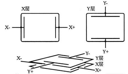
Figure 1. Structure of Four-wire resistive touch screen.
Of course, the four-wire resistive touch screen still has great defects. The B side of the resistive touch screen needs to be frequently touched. The B side of the four-wire resistive touch screen uses ITO[5]. We know that ITO is a very thin oxide metal. In the process of use, small cracks will soon occur. Once the cracks are generated, the current flowing through the place is forced to go around the cracks, and the voltage that should be uniformly distributed will be damaged, and the touch screen will be damaged. It is shown that the crack is inaccurate. With the intensification and increase of cracks, the touch screen will slowly fail, so the short service life is the main problem of the four-wire resistance touch screen.
2.1.2. Five-wire resistance touch screen. The five wire resistive touch screen consists of two layers of resistive film, one layer is a glass panel (ITO glass), and the other layer is an induction layer (ITO film).As illustrated in Figure 2, there are two parallel conductive electrodes arranged on the sensing layer, and the glass panel is also coated with a conductive layer, forming two intersecting resistance networks. [6]In addition, there is a wire called "touch screen four wires" used to measure resistance values. The touch screen circuit will apply a constant voltage to the two conductive electrodes of the sensing layer, forming a voltage gradient. When users touch the surface of the touch screen with their fingers or stylus, the conductive layer on the glass panel will come into contact with the conductive electrode of the sensing layer. The position of the touch points causes an uneven distribution of resistance between the conductive layer and the conductive electrode of the sensing layer on the glass panel. The resistance value near the touch point decreases, while the resistance value in other areas remains unchanged. Through the wires in the "touch screen four wires", [7]the circuit will apply a small current to the conductive layer on the glass panel. Then, by measuring the voltage on the two conductive electrodes of the induction layer, the resistance value of the current passing through the area near the touch point can be obtained. Based on the current measurement results, the touch screen control circuit can calculate the specific position of the touch points. By measuring the resistance values at different positions, the horizontal and vertical coordinates of the touch points can be determined.
The base layer of the five-wire resistance technology touch screen adds the voltage fields in both directions to the conductive working surface of the glass through the precision resistance network. As illustrated in Figure 2, we can simply understand that the voltage fields in both directions are added to the same working surface by time-sharing operation, while the outer nickel gold conductive layer is only used as a pure conductor. The position of the touch point is measured by time-sharing detection of the X and Y-axis voltage values of the inner ITO contact points after touching. The inner ITO of the five-wire resistance touch screen needs four leads, and the outer layer is only used as a conductor. There are five outgoing lines of the touch screen.
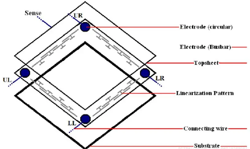
Figure 2. Structure of five-wire resistive touch screen.
As for the advantages of five wire resistive touch screens, the first is higher accuracy: five wire resistive touch screens usually have higher accuracy and accuracy than four wire resistive touch screens. By using an additional touch screen four wire, the circuit can measure resistance values more accurately, providing more precise touch position detection. Secondly, there is a lower touch pressure requirement: compared to a four wire resistive touch screen, a five wire resistive touch screen requires a lower touch pressure to detect touch. This makes it more suitable for users to lightly touch or use small objects such as a stylus for touch operations. There is also better durability: Five wire resistive touch screens are usually more durable than four wire resistive touch screens. Due to the need for resistance testing only in four corners and no current passing through the middle area, the resistance layer in the middle area is less subjected to pressure and wear, thereby improving the durability of the touch screen.
In comparison, the five-wire resistor is superior to the four-wire resistor in ensuring resolution accuracy, but the cost is high, so the price is very high. Five-wire resistance touch screen is the best resistance technology touch screen, which is most suitable for military, medical and industrial control fields.
3. Capacitive touch screen
The capacitive touch screen is composed of a glass panel, a conductive layer, and an induction electrode. The glass panel is coated with conductive materials (such as ITO film), [8]forming a flat conductive layer. Apply current to the induction electrode below the conductive layer. The current applied on the induction electrode will form an electric field distribution. When there is no touch, the electric field distribution is uniform. When users touch the surface of the touch screen with their fingers or stylus, the electric field distribution of the touch screen may be altered due to the charge carried by the human body or stylus. The contact of touch points introduces additional capacitance, which changes the distribution of electric fields on the touch screen. The capacitance value near the touch point increases, while the capacitance value in other areas remains low. The induction electrode will detect changes in the distribution of the electric field and measure the current on the induction electrode. The increase in capacitance near the touch point leads to a change in current. By measuring the current change on the induction electrode, the touch screen control circuit can calculate the specific position of the touch point. Based on the amplitude and distribution of current changes, the horizontal and vertical coordinates of the touch points can be determined.
The specific structure of the capacitive touch screen is shown in Figure 3.
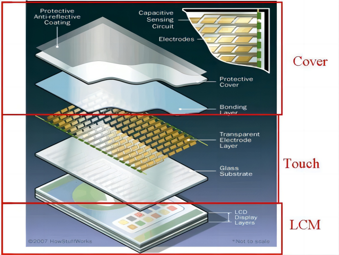
Figure 3. Structure of capacitive touchscreen.
The capacitive touch screen has fast response speed and long service life, but the defect caused by its own working principle is that if there are other electric fields around the screen when the fingers touch the screen, it will interfere with the controller to recognize the touch, resulting in touch misjudgment or touch positioning deviation. Therefore, the capacitive touch screen is greatly affected by the environment, prone to "drift", poor anti-interference ability, and relatively serious reflection The touch accuracy is not high.Capacitive touch screen can be divided into surface type and projection type. The former has the advantages of simple structure, low price and relatively simple detection circuit; The latter can realize the irreplaceable advantage of multi-touch.
3.1. Surface capacitive touch
The surface capacitive touch screen only contains a single ITO conductive layer. The structure is that the bottom glass is coated with ITO conductive layer. ITO is a transparent conductive material, and its upper layer is a protective coating. Four electrodes are drawn from the four corners of the conductive layer and connected to the controller.
Before power-on and touching, there is a uniform electric field on the screen surface. When the human finger or other conductor touches the screen surface, the charge on the touch screen surface is guided to the ground through the human body. In order to recover these charges, as shown in Figure 4, the electrodes at the four corners will send charges to the touch point. The generated current value is inversely proportional to the distance to the four corners, so the controller can determine the touch position. But also because of the working principle of the surface capacitive touch screen, it can only realize the recognition of single touch.
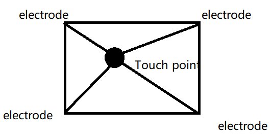
Figure 4. Principle of surface capacitive touch screen.
3.2. Projection capacitive touchscreen
The electrode diagram of the projection capacitive touch screen adopts a multi-layer ITO design. The transverse (X-axis) electrode TX is the driving electrode, and the longitudinal (Y-axis) electrode RX is the induction electrode, which is cross-distributed, as shown in Figure 5. [9] After the finger touches the screen, a coupling capacitance is formed between the finger and the screen surface, which changes the original inductive capacitance value. The controller scans the electrode to detect the change in the capacitance, and the coordinate value of the touch point can be obtained after analog-to-digital conversion and data processing[10]. Compared with surface type, capacitive touch screen can realize multi-point touch.
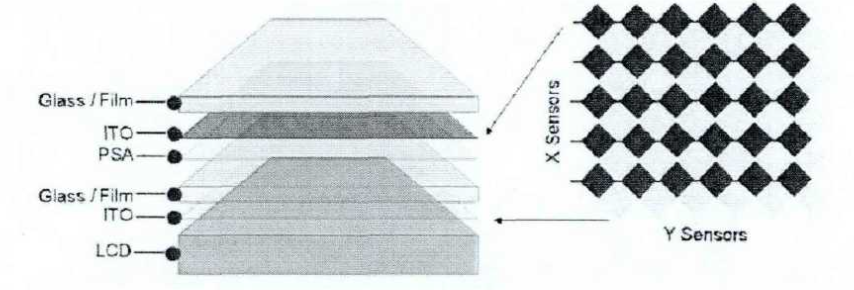
Figure 5. Principle of projection capacitive touch screen.
The projection capacitive touch screen is also divided into two types, namely self-capacitive and mutual capacitive.
3.3. Self-capacitance type
The self capacitive projection capacitive touch screen consists of two conductive layers (ITO film). The top conductive layer forms a touch panel, while the bottom conductive layer is divided into a series of small conductive coils. The touch screen control circuit will sequentially apply driving signals to the conductive coils of the bottom conductive layer. Each conductive coil will be activated in a specific order. [11]When the conductive coil of the bottom conductive layer is activated, an electric field is generated. When users touch the surface of the touch screen with their fingers or stylus, it can cause changes in the charge distribution on the touch panel. These charge changes will be sensed by the conductive coil of the bottom conductive layer. The contact of touch points introduces additional capacitance, which changes the distribution of electric fields on the touch screen. The capacitance value near the touch point increases, while the capacitance value in other areas remains low. The induction circuit measures the changes in charge sensed on the bottom conductive layer and converts them into position data of touch points. By analyzing the charge changes on the bottom conductive layer, the touch screen control circuit can calculate the specific position of the touch points. Based on the amplitude and distribution of capacitance changes, the horizontal and vertical coordinates of the touch points can be determined.[12]
3.4. Mutual capacitance type
The mutual capacitance projection capacitive touch screen consists of two conductive layers (ITO film). The top conductive layer forms a touch panel, while the bottom conductive layer is divided into a series of small conductive coils. The touch screen control circuit will sequentially apply driving signals to the conductive coils of the bottom conductive layer. Each conductive coil will be activated in a specific order. When the conductive coil of the bottom conductive layer is activated, an electric field is generated. The conductive coil on the top conductive layer will continuously receive driving signals from the bottom conductive layer. [13]When users touch the surface of the touch screen with their fingers or stylus, the electric field distribution on the touch panel will be altered due to the charge carried by the human body or stylus. The contact of touch points introduces additional capacitance, which changes the distribution of electric fields on the touch screen. The capacitance value near the touch point increases, while the capacitance value in other areas remains low. The conductive coil on the top conductive layer senses changes in the electric field on the bottom conductive layer and converts them into changes in the received signal. By analyzing the received signal changes on different conductive coils, the touch screen control circuit can detect the position and contact pressure of multiple touch points. By comparing the received signals on different conductive coils, it is possible to distinguish the contact between different touch points.[14] Based on the amplitude and distribution of the received signal, the touch screen control circuit can calculate the specific position of each touch point and transmit it to the corresponding application program.
Compared with other capacitive touch screens (such as self capacitive touch screens), mutual capacitive projection capacitive touch screens have the following advantages: first, the accuracy of Multi-touch: mutual capacitive projection capacitive touch screens can more accurately detect and track the positions and actions of multiple touch points. It can provide higher touch resolution and more accurate touch positioning, making Multi-touch applications and gesture operations more accurate and smooth. Secondly, the differentiation of Multi-touch: mutual capacitive projection capacitive touch screen can distinguish the contact between different touch points, even if multiple touch points touch the screen at the same time, it can also accurately identify the position and operation of each touch point. This differentiation enables Multi-touch applications to achieve more interaction possibilities and functions. There is also anti-interference ability: mutual capacitance projection capacitive touch screen has good anti-interference ability. Due to its use of cross induction, it can effectively resist external environmental interference (such as electromagnetic interference and stray charges), providing more stable and reliable touch performance. [15]Finally, sensitivity: The mutual capacitance projection capacitive touch screen has high sensitivity and can respond quickly to slight touch. It can sense more subtle changes in touch pressure, making the interaction between users and devices more natural and flexible.
4. Result
In this paper, the resistive and capacitive touch screens that are most widely used in touch screens are analyzed in detail, and their working principles and structures are introduced. Next, I will compare the advantages and disadvantages of resistive and capacitive touch screens and different types of capacitive touch screens in the form of tables, so as to provide a more intuitive manifestation of touch screen performance.
Table 1. Comparison between resistive touch screen and capacitive touch screen.
Resistive touch screen | Capacitive touch screen | |
service life | Short | long |
Input method | Need to write hard | Gently touch |
Size | middle and small | small |
Interference problem | Not easy | easy |
cost | Lower | Higher |
Multitouch | cannot | Can |
Table 2. Comparison between surface capacitive touch screen and projection capacitive touch screen.
surface capacitive touch screen | projection capacitive touch screen | |
structure | Simple | complex |
cost | Lower | Higher |
Circuit detection | easy | Not easy |
Multitouch | cannot | Can |
Table 3. Comparison between Self-capacitance type and Mutual capacitance type.
Self-capacitance type | Mutual capacitance type | |
wiring | complex | Simple |
Acquisition speed | slow | fast |
power dissipation | high | low |
Signal stability | Lower | Higher |
Multitouch | cannot | Can |
It can be seen from the above table 1 that although resistive touch screen and capacitive touch screen have their advantages and disadvantages, the cost of a resistive touch screen is very low because of its mature technology, with the wide application of multi-point touch on smartphones, the resistive touch screen that can only achieve single-point operation can no longer meet the needs of users, so capacitive touch screen has become the mainstream of the market. In the table 2 and 3, the mutual capacitive projection capacitive touch screen has become the main direction of the development of the touch screen industry because of its low power consumption, relatively stable signal and fast data acquisition speed.
5. Discussion
Although capacitive touch screen has become the mainstream technology in the current market, there are still some research directions and development prospects in the future. Here are some possible research directions and trends for the capacitive touch screen industry:
(1) High precision and sensitivity: Although capacitive touch screens have relatively high accuracy and sensitivity, they are expected to be further improved in future research. Researchers can work on improving sensor technology, signal processing algorithms, and other aspects to achieve more accurate and fast touch location and response.
(2) Ultra-thin and flexible design: With the development of bendable display technology and wearable devices, capacitive touch screens can move in the direction of thinner and more flexible. Researchers can explore new materials and structural designs to achieve thinner, more flexible capacitive touch screens to suit the needs of different shapes and application scenarios.
(3) Multitouch and Gesture recognition: Multitouch is already a standard feature on capacitive touch screens, but future research could further improve the performance and functionality of multitouch. In addition, advances in gesture recognition technology could extend the way touch screens interact, allowing users to use more gestures to achieve more complex actions.
(4) Anti-interference and noise reduction: In some special environments, capacitive touch screens may be affected by interference and noise, resulting in a decline in the accuracy of touch positioning. Future research could focus on reducing the impact of interference and noise and improving the performance of touch screens in complex environments.
(5) Haptic feedback and augmented reality: Haptic feedback technology can provide users with richer tactile experiences on touch screens, such as simulating the texture and touch of objects. In addition, combined with augmented reality technology, capacitive touch screens can provide a more intuitive interface for virtual reality applications.
(6) Intelligent and adaptive: With the help of artificial intelligence and machine learning, capacitive touch screens enable more intelligent and adaptive interactive experiences. The touch screen learns user operation habits and behavior patterns, and automatically adjusts the interface layout and function Settings based on different scenarios and requirements to provide personalized and intelligent user experience.
To sum up, future research directions of capacitive touch screen industry mainly include improving performance, exploring new design forms, enhancing interactive experience and realizing intelligence. These research directions are expected to further promote the development of capacitive touch screen technology and provide users with a better touch experience.
6. Conclusion
Due to the different working principle compared with resistive touch screen, capacitive touch screen has the following advantages: multi-touch support, high sensitivity and accuracy, high transparency and durability, fast response speed and so on. As a variant of the capacitive touch screen, the mutual capacitive projective capacitive touch screen has made breakthroughs in the following aspects: higher transparency and image quality, higher sensitivity and accuracy, multi-touch and finger recognition function, higher anti-interference capability, more comfortable touch feeling and support for high-speed touch and pen input.
As a new frontier technology, capacitive touch screen technology has a very good prospect in the future technology development due to its wide application and broad development direction. Capacitive touch screen technology may continue to make progress in many aspects. Examples include flexibility and bendability, enhanced touch experience, intelligence and adaptability, cross-device and cross-platform compatibility, and so on.
Overall, capacitive touch screens offer clear advantages in terms of multi-touch, sensitivity, transparency and durability, and future developments include improvements in flexibility, haptic feedback, intelligence and cross-device compatibility. These developments will further promote the application of capacitive touch screen technology and improve user experience.
References
[1]. Ding, H.J., et al., Deep Learning-Enabled MXene/PEDOT:PSS Acoustic Sensor for Speech Recognition and Skin-Vibration Detection. ADVANCED INTELLIGENT SYSTEMS, 2022. 4(10).
[2]. Ruppel, C., Acoustic Wave Filter Technology-A Review. IEEE TRANSACTIONS ON ULTRASONICS FERROELECTRICS AND FREQUENCY CONTROL, 2017. 64(9): p. 1390-1400.
[3]. Song, T.G., et al., A 50.7-dB-DR Finger-Resistance Extracting Multi-Touch Sensor IC for Soft Classification of Fingers Contacted on 6.7-in Capacitive Touch Screen Panel. IEEE JOURNAL OF SOLID-STATE CIRCUITS, 2021. 56(11): p. 3470-3485.
[4]. Kim, D.K., et al., A Touchpad for Force and Location Sensing. ETRI JOURNAL, 2010. 32(5): p. 722-728.
[5]. Hecht, D.S., et al., Carbon-nanotube film on plastic as transparent electrode for resistive touch screens. JOURNAL OF THE SOCIETY FOR INFORMATION DISPLAY, 2009. 17(11): p. 941-946.
[6]. Sharma, R.K., et al., Microwave integrated circuits fabrication on alumina substrate using pattern up direct electroless nickel and immersion Au plating and study of its properties. MICROELECTRONIC ENGINEERING, 2013. 108: p. 45-49.
[7]. Luo, C.C., et al., Compressive Sensing for Sparse Touch Detection on Capacitive Touch Screens. IEEE JOURNAL ON EMERGING AND SELECTED TOPICS IN CIRCUITS AND SYSTEMS, 2012. 2(3): p. 639-648.
[8]. Luo, C.C., et al., Compressive Sensing for Sparse Touch Detection on Capacitive Touch Screens. IEEE JOURNAL ON EMERGING AND SELECTED TOPICS IN CIRCUITS AND SYSTEMS, 2012. 2(3): p. 639-648.
[9]. Lee, J., et al., An Analysis of Electrode Patterns in Capacitive Touch Screen Panels. JOURNAL OF DISPLAY TECHNOLOGY, 2014. 10(5): p. 362-366.
[10]. Yang, I.S. and O.K. Kwon, A Touch Controller Using Differential Sensing Method for On-Cell Capacitive Touch Screen Panel Systems. IEEE TRANSACTIONS ON CONSUMER ELECTRONICS, 2011. 57(3): p. 1027-1032.
[11]. Kwon, O.K., J.S. An and S.K. Hong, Capacitive Touch Systems With Styli for Touch Sensors: A Review. IEEE SENSORS JOURNAL, 2018. 18(12): p. 4832-4846.
[12]. Liu, W.J., et al., Device/Circuit Mixed-Mode Simulations for Analysis and Design of Projected-Capacitive Touch Sensors. JOURNAL OF DISPLAY TECHNOLOGY, 2015. 11(2): p. 204-208.
[13]. Lee, C.J., et al., Mutual Capacitive Sensing Touch Screen Controller for Ultrathin Display with Extended Signal Passband Using Negative Capacitance. SENSORS, 2018. 18(11).
[14]. Kang, S.W., et al., Effects of Sn Concentration on Ultrathin ITO Films Deposited Using DC Magnetron Sputtering. JOURNAL OF NANOELECTRONICS AND OPTOELECTRONICS, 2012. 7(5): p. 494-497.
[15]. Park, K., et al., 17-aF $_{{rms}}$ Resolution Noise-Immune Fingerprint Scanning Analog Front-End for Under-Glass Mutual-Capacitive Fingerprint Sensors. IEEE TRANSACTIONS ON CIRCUITS AND SYSTEMS I-REGULAR PAPERS, 2022. 69(3): p. 1135-1147.e .
Cite this article
Hu,R. (2024). The advantages and comparison of resistive touch screens and capacitive touch screens. Applied and Computational Engineering,30,94-103.
Data availability
The datasets used and/or analyzed during the current study will be available from the authors upon reasonable request.
Disclaimer/Publisher's Note
The statements, opinions and data contained in all publications are solely those of the individual author(s) and contributor(s) and not of EWA Publishing and/or the editor(s). EWA Publishing and/or the editor(s) disclaim responsibility for any injury to people or property resulting from any ideas, methods, instructions or products referred to in the content.
About volume
Volume title: Proceedings of the 2023 International Conference on Machine Learning and Automation
© 2024 by the author(s). Licensee EWA Publishing, Oxford, UK. This article is an open access article distributed under the terms and
conditions of the Creative Commons Attribution (CC BY) license. Authors who
publish this series agree to the following terms:
1. Authors retain copyright and grant the series right of first publication with the work simultaneously licensed under a Creative Commons
Attribution License that allows others to share the work with an acknowledgment of the work's authorship and initial publication in this
series.
2. Authors are able to enter into separate, additional contractual arrangements for the non-exclusive distribution of the series's published
version of the work (e.g., post it to an institutional repository or publish it in a book), with an acknowledgment of its initial
publication in this series.
3. Authors are permitted and encouraged to post their work online (e.g., in institutional repositories or on their website) prior to and
during the submission process, as it can lead to productive exchanges, as well as earlier and greater citation of published work (See
Open access policy for details).
References
[1]. Ding, H.J., et al., Deep Learning-Enabled MXene/PEDOT:PSS Acoustic Sensor for Speech Recognition and Skin-Vibration Detection. ADVANCED INTELLIGENT SYSTEMS, 2022. 4(10).
[2]. Ruppel, C., Acoustic Wave Filter Technology-A Review. IEEE TRANSACTIONS ON ULTRASONICS FERROELECTRICS AND FREQUENCY CONTROL, 2017. 64(9): p. 1390-1400.
[3]. Song, T.G., et al., A 50.7-dB-DR Finger-Resistance Extracting Multi-Touch Sensor IC for Soft Classification of Fingers Contacted on 6.7-in Capacitive Touch Screen Panel. IEEE JOURNAL OF SOLID-STATE CIRCUITS, 2021. 56(11): p. 3470-3485.
[4]. Kim, D.K., et al., A Touchpad for Force and Location Sensing. ETRI JOURNAL, 2010. 32(5): p. 722-728.
[5]. Hecht, D.S., et al., Carbon-nanotube film on plastic as transparent electrode for resistive touch screens. JOURNAL OF THE SOCIETY FOR INFORMATION DISPLAY, 2009. 17(11): p. 941-946.
[6]. Sharma, R.K., et al., Microwave integrated circuits fabrication on alumina substrate using pattern up direct electroless nickel and immersion Au plating and study of its properties. MICROELECTRONIC ENGINEERING, 2013. 108: p. 45-49.
[7]. Luo, C.C., et al., Compressive Sensing for Sparse Touch Detection on Capacitive Touch Screens. IEEE JOURNAL ON EMERGING AND SELECTED TOPICS IN CIRCUITS AND SYSTEMS, 2012. 2(3): p. 639-648.
[8]. Luo, C.C., et al., Compressive Sensing for Sparse Touch Detection on Capacitive Touch Screens. IEEE JOURNAL ON EMERGING AND SELECTED TOPICS IN CIRCUITS AND SYSTEMS, 2012. 2(3): p. 639-648.
[9]. Lee, J., et al., An Analysis of Electrode Patterns in Capacitive Touch Screen Panels. JOURNAL OF DISPLAY TECHNOLOGY, 2014. 10(5): p. 362-366.
[10]. Yang, I.S. and O.K. Kwon, A Touch Controller Using Differential Sensing Method for On-Cell Capacitive Touch Screen Panel Systems. IEEE TRANSACTIONS ON CONSUMER ELECTRONICS, 2011. 57(3): p. 1027-1032.
[11]. Kwon, O.K., J.S. An and S.K. Hong, Capacitive Touch Systems With Styli for Touch Sensors: A Review. IEEE SENSORS JOURNAL, 2018. 18(12): p. 4832-4846.
[12]. Liu, W.J., et al., Device/Circuit Mixed-Mode Simulations for Analysis and Design of Projected-Capacitive Touch Sensors. JOURNAL OF DISPLAY TECHNOLOGY, 2015. 11(2): p. 204-208.
[13]. Lee, C.J., et al., Mutual Capacitive Sensing Touch Screen Controller for Ultrathin Display with Extended Signal Passband Using Negative Capacitance. SENSORS, 2018. 18(11).
[14]. Kang, S.W., et al., Effects of Sn Concentration on Ultrathin ITO Films Deposited Using DC Magnetron Sputtering. JOURNAL OF NANOELECTRONICS AND OPTOELECTRONICS, 2012. 7(5): p. 494-497.
[15]. Park, K., et al., 17-aF $_{{rms}}$ Resolution Noise-Immune Fingerprint Scanning Analog Front-End for Under-Glass Mutual-Capacitive Fingerprint Sensors. IEEE TRANSACTIONS ON CIRCUITS AND SYSTEMS I-REGULAR PAPERS, 2022. 69(3): p. 1135-1147.e .