


With the continuous rapid growth of China’s economy, the construction of power grids is also developing at a high speed. The power outages caused by the renovation, expansion, or maintenance of conventional substations are increasingly highlighting their impact on the economy and daily life. To address these issues, mobile substations suitable for different voltage levels and capacities have emerged. As the capacity of mobile substations continues to increase, the ground fault current flowing through the grounding grid also becomes larger, increasing the risk of accidents due to poor grounding.
The rational design of the grounding grid is a crucial prerequisite for ensuring the safe and reliable operation of mobile substations. Standardizing the grounding design of mobile substations can reduce subsequent design work and on-site construction. Therefore, based on these requirements, this paper discusses the grounding grid design for a 35kV mobile substation.
1. Introduction to mobile substations
A mobile substation, simply put, is a movable substation placed on a vehicle. It is equipped with complete primary and secondary equipment and can perform all the functions of a conventional substation. According to user requirements, different equipment configurations can be applied to the high and low voltage sides. Taking a 35kV mobile substation as an example, it generally consists of two semi-trailers: a 35kV high-voltage substation vehicle and a 10kV medium-voltage distribution vehicle, which are electrically connected through high-voltage cables.
2. Grounding scheme design for 35kV mobile substations
Grounding refers to the connection of certain conductive parts of electrical installations or facilities in a power system or building to the grounding device through grounding wires. A grounding device is a metal conductor buried directly in the ground and in direct contact with the earth. Grounding can be categorized into system grounding, protective grounding, lightning protection grounding, and anti-static grounding based on its function.
This paper focuses on the protective grounding of mobile substations. Protective grounding means connecting one or more points of a system, installation, or equipment to the ground to ensure electrical safety. Considering the rectangular layout of the vehicle and its equipment, the grounding grid of a mobile substation is best designed as a closed grounding ring around the vehicle’s perimeter. Additionally, grounding points connected to the main grounding grid are extended from around the vehicle. Using a grounding ring network allows the entire equipment to form a more reliable equipotential grounding. Moreover, adding grounding devices within the grounding ring network creates a ring-shaped mesh grounding, improving the uniformity of the electric field distribution within the grounding ring during high current conditions.
2.1. Protective grounding of electrical equipment and requirements
The equipment support, metal framework, semi-trailer body, and other accessories of the mobile substation should be reliably electrically connected to the auxiliary grounding ring network. The following parts of the electrical equipment in the mobile substation should also be reliably connected to the auxiliary grounding ring network:
(1) Bases and enclosures of transformers and high-voltage apparatus;
(2) Secondary windings of transformers;
(3) Electrical equipment drive mechanisms;
(4) Metal frameworks of switch cabinets, secondary protection panels, and control boxes;
(5) Grounding terminals of HGIS (Hybrid Gas Insulated Switchgear);
(6) Outer sheaths of armored cables;
(7) Cable trays and cable bridges;
(8) Prefabricated cabins of the mobile substation.
2.2. Grounding ring network design for substation vehicle
The substation vehicle is equipped with an auxiliary grounding ring network on the vehicle body. Each grounding point should be connected to the auxiliary grounding ring network as close as possible. For ease of connection to the auxiliary grounding ring network, the grounding wires should have crimped terminals, and the grounding copper bars should have reserved bolt holes. Each grounding point can be connected using hot-dip galvanized bolts with a diameter of not less than 12mm. The grounding copper bars of each switch cabinet and protection panel inside the main switch box should be sequentially connected and led out to the auxiliary grounding ring network outside the prefabricated cabin, collectively forming the substation vehicle grounding system. Finally, two points from each side of the vehicle body should be connected to the main grounding grid.
Taking a specific project as an example, this system is a neutral point non-directly grounded system. The maximum short-time withstand current of the grounding circuit can reach 87% of the rated short-time withstand current of the main circuit. The rated short-time withstand current and duration for the equipment in this project are 40kA/3s. The auxiliary grounding ring network conductor is made of copper, with a minimum cross-sectional area calculated as follows:
\( S_{g}≥\frac{I_{g}}{C}\sqrt[]{t_{e}} \)
Where:
\( S_{g} \) is the minimum cross-sectional area of the grounding conductor (line);
\( I_{g} \) is the maximum asymmetrical current through the grounding conductor (line) (A), determined by the equipment’s rated short-time withstand current;
\( t_{e} \) is the equivalent duration of the grounding fault;
C is the thermal stability coefficient of the grounding conductor (line) material, determined by the type, properties, and maximum allowable temperature of the material, as well as the initial temperature of the grounding conductor (line) before the fault. The thermal stability coefficient C for copper is taken as 210.
When the substation’s relay protection device is configured with fast primary protection, near-ground backup protection, breaker failure protection, and automatic reclosing, \( t_{e} \) should be determined according to the following formula:
\( t_{e}≥t_{m}+t_{f}+t_{o} \)
Where:
\( t_{m} \) is the primary protection action time (s);
\( t_{f} \) is the breaker failure protection action time (s);
\( t_{o} \) is the breaker opening time (s).
This project’s design requires the primary protection action time to be 35ms, the breaker failure protection action time to be considered as 0.5s, and the breaker opening time to be 60ms.
Using the above formula, it can be calculated that the area of the grounding bar for the auxiliary grounding ring network of the substation vehicle should be ≥115.7mm². Considering different backup protection designs and that the equivalent duration of the breaker grounding fault will certainly not exceed 1s, it is deemed appropriate to consider 1s, making the area of the auxiliary grounding ring network ≥150mm². For this project, a 40mm*4mm copper bar is used as the auxiliary grounding ring network. The outer edge of the grounding ring network should be closed, and each corner of the outer edge should be rounded with a radius not less than half the spacing of the adjacent equipotential bonding strap. The layout of the substation vehicle is shown in Figure 1, and the auxiliary grounding ring network of the substation vehicle is shown in Figure 2.
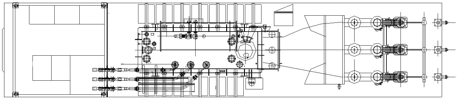
Figure 1. Layout of the Substation Vehicle

Figure 2. Auxiliary Grounding Ring Network of the Substation Vehicle
The prefabricated cabin’s bottom cable layer is equipped with an auxiliary grounding ring network, divided into primary grounding copper bars and equipotential grounding copper bars. The equipotential grounding copper bars are separated from the cabin bottom by pillar insulators. All electrical equipment bases, switchgear, and screen cabinets are connected to the auxiliary primary grounding copper bars. The cross-sectional area of the connecting conductors should be calculated according to the above formula to meet the equivalent thermal and mechanical requirements. The cross-sectional area of the grounding copper bars in the secondary screen cabinets inside the prefabricated cabin should be not less than 50mm² and connected to the equipotential grounding network of the cabin bottom cable layer with copper cables. Inside the switchgear, bare copper bars with a cross-sectional area of not less than 100mm² are used, and copper cables with a cross-sectional area of not less than 100mm² are used to connect to the equipotential grounding network of the cabin bottom cable layer. Suitable terminals are used at both ends of the grounding conductors to connect to the equipment and auxiliary grounding ring network. The electrical contact area of the terminals should be compatible with the cross-sectional area of the grounding conductor, but not less than 160mm².
2.3. Grounding ring network design for distribution vehicle
An auxiliary circular grounding network is used inside the distribution vehicle’s prefabricated cabin. The grounding copper bars in adjacent switchgear and secondary screen cabinets are sequentially connected, while non-adjacent cabinets are connected along the cable trays or in the cabin’s cable layer to form a closed grounding ring network. Finally, two points are led out from each side of the prefabricated cabin to connect to the main grounding grid. The design of the distribution vehicle’s auxiliary grounding ring network is shown in Figure 3.
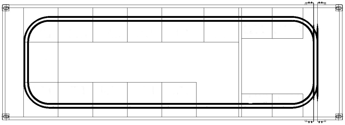
Figure 3. Auxiliary Grounding Ring Network for Distribution Vehicle
3. Considerations for grounding design
As a special type of substation, the mobile substation must ensure reliable grounding for all electrical equipment and supporting structures according to the provisions of “Grounding of AC Electrical Installations.” When designing the grounding system, the following points should be noted:
Each grounding part of the electrical equipment should be connected to the auxiliary grounding ring network via separate grounding wires. Several grounding parts requiring grounding should not be connected in series on a single wire.
(1) Grounding devices should be corrosion-resistant (galvanized). It is advisable to use bolt connections for all electrical equipment and supporting structures connected to the grounding ring network. The overlap length must be twice the width of flat iron or six times the diameter of round steel.
(2) The neutral point of the main transformer, HGIS, and voltage transformers must each be connected to the primary grounding ring network of the mobile substation using two grounding wires at different locations. For the equipotential grounding ring network of the mobile substation, at least four grounding wires with a minimum cross-sectional area of 50mm² should be reliably connected to the main grounding grid at the front, middle, or rear of the semi-trailer according to its length.
4. Conclusion
The mobile substation serves as an excellent emergency power solution, offering remarkable flexibility and speed. It provides a more reliable power backup during situations such as substation renovations, expansions, and major natural disasters. Being a prefabricated substation, all equipment installation and wiring are predominantly completed in the factory. Therefore, by integrating a dedicated auxiliary grounding ring network system into the mobile substation, the site only requires connecting this auxiliary grounding ring network to the main grounding grid to complete the station’s grounding. This significantly reduces on-site construction work while enhancing standardization. The mobile substation holds promising market prospects. Through further research on its technical solutions, the reliability of the mobile substation can be enhanced, playing a crucial role in ensuring future power reliability and emergency response in disaster situations.
References
[1]. Guo, R., & Wu, J. (2018). Seismic design scheme for mobile substations. Electronic Technology and Software Engineering.
[2]. Bao, H. Q. (2013). Large-scale mobile substations. Electric Applications.
[3]. Yang, S. (2015). Discussion on the grounding grid of mobile substations. Guizhou Electric Power Technology.
[4]. National Standard of the People’s Republic of China. (2006). GB 3906—2006: AC metal-enclosed switchgear and control equipment rated from 3.6kV to 40.5kV.
[5]. National Standard of the People’s Republic of China. (2016). GB 50169—2016: Installation engineering for grounding devices - Construction and acceptance specification for grounding devices.
[6]. Power Industry Standard of the People’s Republic of China. (1997). DL/T 621—1997: Grounding of AC electrical installations.
Cite this article
Mao,R.;Du,T.;Shu,Y.;Shi,M.;Dai,L. (2024). Design of grounding scheme for mobile substation. Advances in Engineering Innovation,9,1-5.
Data availability
The datasets used and/or analyzed during the current study will be available from the authors upon reasonable request.
Disclaimer/Publisher's Note
The statements, opinions and data contained in all publications are solely those of the individual author(s) and contributor(s) and not of EWA Publishing and/or the editor(s). EWA Publishing and/or the editor(s) disclaim responsibility for any injury to people or property resulting from any ideas, methods, instructions or products referred to in the content.
About volume
Journal:Advances in Engineering Innovation
© 2024 by the author(s). Licensee EWA Publishing, Oxford, UK. This article is an open access article distributed under the terms and
conditions of the Creative Commons Attribution (CC BY) license. Authors who
publish this series agree to the following terms:
1. Authors retain copyright and grant the series right of first publication with the work simultaneously licensed under a Creative Commons
Attribution License that allows others to share the work with an acknowledgment of the work's authorship and initial publication in this
series.
2. Authors are able to enter into separate, additional contractual arrangements for the non-exclusive distribution of the series's published
version of the work (e.g., post it to an institutional repository or publish it in a book), with an acknowledgment of its initial
publication in this series.
3. Authors are permitted and encouraged to post their work online (e.g., in institutional repositories or on their website) prior to and
during the submission process, as it can lead to productive exchanges, as well as earlier and greater citation of published work (See
Open access policy for details).
References
[1]. Guo, R., & Wu, J. (2018). Seismic design scheme for mobile substations. Electronic Technology and Software Engineering.
[2]. Bao, H. Q. (2013). Large-scale mobile substations. Electric Applications.
[3]. Yang, S. (2015). Discussion on the grounding grid of mobile substations. Guizhou Electric Power Technology.
[4]. National Standard of the People’s Republic of China. (2006). GB 3906—2006: AC metal-enclosed switchgear and control equipment rated from 3.6kV to 40.5kV.
[5]. National Standard of the People’s Republic of China. (2016). GB 50169—2016: Installation engineering for grounding devices - Construction and acceptance specification for grounding devices.
[6]. Power Industry Standard of the People’s Republic of China. (1997). DL/T 621—1997: Grounding of AC electrical installations.