


1 Introduction
In an era defined by unprecedented technological advancements, the manufacturing industry is at the peak of a transformation promising to change the fundamental concept of production.[1] At the core of this revolution lies the integration of digital technologies and data analytics with industrial processes, which give rise to what is commonly referred to as "Smart Manufacturing". This approach to change indicates a future in which manufacturing processes are not just efficient, reactive and data-driven, but intelligent, proactive, and insights-informed.[2]
The integration in smart manufacturing leads to a range of transformative benefits, reshaping the landscape of production. It enables real-time monitoring and control of production lines, predictive maintenance, quality optimization, and the capability to adapt to market demands. As a result, manufacturers can enhance operational efficiency, and reduce downtime, save costs, and ultimately, provide higher-quality products to consumers [3].
In this report, we explore the complex fields of digital technologies and data analytics in smart manufacturing, and introduce the technologies, strategies, and case studies that are promising in the future of the manufacturing industry, which explores the evolving role of digital twins and data analytics in streamlining supply chains, improving product design, ensuring product quality, and fostering sustainability.[4]
A noteworthy aspect of this project is the unique fusio with the world of additive manufacturing which is also known as 3D printing. Importing G-codes generated from Fusion 360 from Autodesk and tailored for the Uprint SE 3D printer in our lab, we take a voyage through the world of NVIDIA's cutting-edge Omniverse platform, and have achieved an astounding milestone - the simulation and visualization of the movements and actions of the 3D printer in a virtual environment.
This endeavor never stops at simulation. Due to Omniverse platform, such a new system for digital twins, our path continues as we to push forward the innovation in manufacturing. After successfully replicating the real printing process in Omniverse based on G-codes, our next aspiration is to achieve augmented reality, which has been proved to be feasible in Robotics and production lines.[5] We aim to mirror the real-time movements of the 3D printer in our lab by synchronizing data with the cameras which we have strategically positioned. Moreover, in the future, predictive analytics could be of more use and become more powerful with machine learning. Imagine a world where we can analyze the post-date data from experiments or manufacturing processes to predict how long a new model will take to print and estimate the material required for the process.[6] This is the horizon of smart manufacturing, where data becomes foresight and efficiency is maximized.
Within the pages that follow, we will discuss the real-world applications, the challenges we may be faced with, and the opportunities that hide on this transformative path. The report is designed to reveal readers with the knowledge and the full potential of digital twins, data analytics in smart manufacturing. In the conclusion, we focus on the advantages, limitations, and of possible future improvements in Omniverse digital twins with data analytics.
2 Methodology
This chapter describes the detailed processes and methods to achieve the generation of G-code in Autodesk Fusion 360 based on uPrint SE 3D printer and assigned model to fabricate, and to import the CAD files into NVIDIA Omniverse USD Composer and transfer them into USD files to build up the environment. The innovation of this project lies on the connection between Fusion 360 and Omniverse, and achievements on using G-codes to replicate the movements of 3D printers in the digital twins, and it will be introduced later in the next chapter.
2.1 G-code generation in Fusion 360 for UPrint SE
G-code serves as the most widely employed programming language for 3D printing and plays a key role in computer-aided manufacturing (CAM) to control in 3D printer slicer applications, where it is used to instruct and guide the printing process. Apart from Fusion 360, we also tried other CAM software as Mastercam, and SolidWorks CAM, to generate the G-code for the 3D printer, but at last we opt to use Fusion 360 from Autodesk, for its wide compatibilities for different types of CAD formation, powerful integration of many functions, ease of use and clear operation appearance.
Due to the differences of operations resulted from different versions of Fusion 360, we used in the currently latest version, as Fusion 360 2.0.17453 x86_64, for educational purpose. And the system requirements are to mention in the next section where the Omniverse platform is introduced, since Omniverse system demands higher level of hardware to operate. Fusion 360 has integrated numerous functions and extensions for engineering industry, which allows us to create the models for different types of objects. As Figure 1 shows, we successfully built up the components of uPrint SE, and assembled them into a whole, as an exact model for uPrint SE 3D printer which we can also generate from other CAD software like Autodesk Inventor, and SolidWorks. Because in this chapter of the project, we mainly pay attention to the G-code generation in Fusion 360for uPrint SE printer, the detailed processes for building up components, assigned printed parts, or assembling are not being introduced here, Harold Timmis et al. have provided considerate guidance on how to model in Fusion 360.[28] For these models we created, they would be import into Omniverse later to establish the digital twins environment for simulation, which will be introduced in the following content.
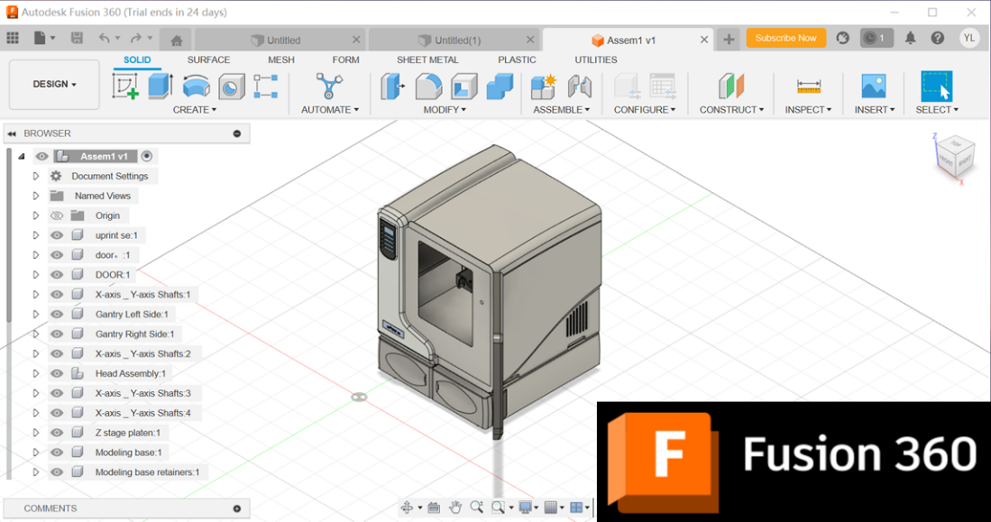
Figure 1. Uprint SE Modeling in Fusion 360, Autodesk.
We uploaded the assigned printed parts into Fusion 360 after getting familiar with the operating pattern. Here we would like to emphasize the formation of the parts, which we suggest in stl. files, due to the great compatibility for 3D printing.[29]
After uploading the printed parts in stl. file into Fusion 360 successfully, we can select all the elements of this part, for it could be made up with several components. Figure 3.1.2 A shows the selection of the Manufacture module in the Main Menu after loading the assigned objects --- Click the Main Menu for the process which originally shows as Design as default and switch it to Manufacture icon where we could opt different manufacturing processes, such as milling and turning to our parts.
As Figure 2 B shows, Set-up icon shows up right after the collection of Manufacture module in the Main Menu, which we click to start the first step of preparation for additive manufacturing processes. A box labeled as Set-up will appear immediately after the click, where we click the Select icon under the Manufacture label, and a box labeled as Machine Library will show up, as Figure 3.1.2 C demonstrates, we firstly choose the manufacturing type as Additive from the right label where turning, milling, grinding and other processing types are optional according to the demands. The machine library in the box will refresh and adjust to the processing type we have just selected, where different models of printers could be seen in the middle since we have chosen Additive, and we can also have access to all the printers in Fusion 360 Library if clicking the icon with the same name on the left.
If we click the label of a certain printer once, we can see the detailed information on the right where the name, the working space required, and the printing area are all being acknowledged. However, the 3D printers in Fusion 360 library are still limited in its types and versions, and for some latest models are not yet installed into, we need to edit our own model for uPrint SE and set it into our own library in Fusion 360.
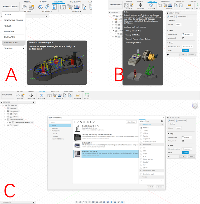
Figure 2. Steps to Prepare the Printing Processes:
A. Select the Manufacture Module in the Main Menu after Loading the Assigned Objects;
B. Set up the Manufacturing Process to the Models;
C. Choose the Additive Manufacturing and the 3D printer in Favor.
It is of great convenience that we are allowed to create the local 3D printer in the Library by providing some certain parameters of our printer. When in the Machine label after confirming the machine process as Additive, we can edit for our printer through click the plus (+) icon from the top and the pen icon to edit the detailed data for it, as Figure 3.1.3 A shows. The first view shows the General page where we can add the name, the label, and the description of the printer, as Figure 3 B. The next step is to input the essential parameters, which include the build size, platform origin, platform mesh and so on, to settle the working platform for the printer in the Platform page, and the detailed content can be read in Figure 3.1.3 C. The main difference between different types of printer station, is the working area with its limits, as home position, temperature, max speed and acceleration from different axis, which can be determined in Limits page in Fusion 360, showed in Figure 3.1.3 D. Due to the fact the features of printers differ from their producers, sometimes we need to alter the parameters concerning the extruders of the printers, and from Figure 3.1.3 E we can learn how to edit these data.
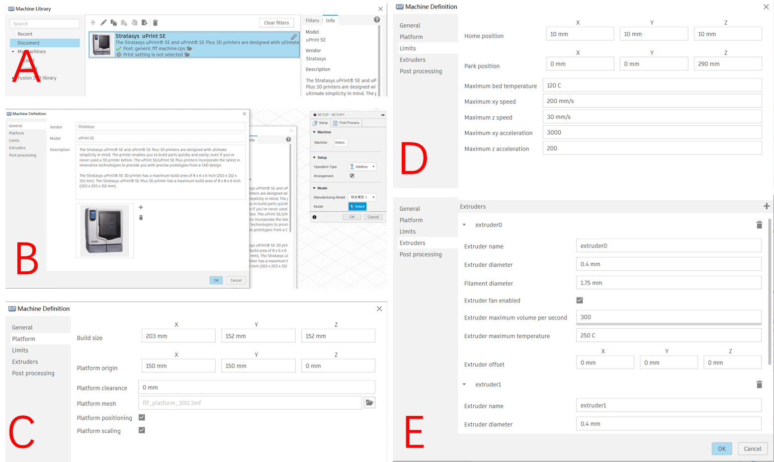
Figure 3. Steps to Edit Uprint SE Printer in the Local Library:
A. Select the Document to Create a New Printer; B. General Description in Machine Definition;
C. Edit in Platform; D. Edit the Positions in Limits; E. Edit the Details for Extruders.
The customized 3D printer we previously used with its parameters stays as the default whenever we select it for the upcoming project, and we can also duplicate the original 3D printer from the Local Library and edit some several ones with the rest of settings unchanged to have another new printer.
Having completed the basic settings for the printer, we moved to the next step for the printing settings. Figure 3.1.4 A shows us the first step closer to the generation of the printing simulation, which is to select the components needed to print, and click the OK button on the right box where we have completed the setting for the printer. Then the print settings library comes out for us to decide which kind of printing technology we would like to apply to this printing process, showed as Figure 3.1.4 B, and we can edit the parameters in Print Process Editor page, based on the instruction of our printer, as Figure 3.1.4 C, just like what we have already done in the printer settings. After all the settings completed, it may result in read-alert to the model we need to print, with a yellow circle marked in front of the name of the part on the left side of the page, which exactly showed as Figure 3.1.4 D, and it results from the lack of Generate process. Click the Generate icon from the Action menu and wait for the yellow circle mark becomes green which suggest the generation has completed. To guarantee the process is correct and fits the normal sequence of printing --- usually from the bottom to the up top when there is no support structures, we need to generate the simulation toolpath to have a video of the whole printing process, by clicking the bottom on the right, as Figure 3.1.4 E shows. The video screenshot of our example is showed in Figure 4 F, and we and move the progress bar at the bottom of the screen to adjust the simulation. If there is anything unexpected, we may need to check once again on the previous settings, especially on the working area of the printer.
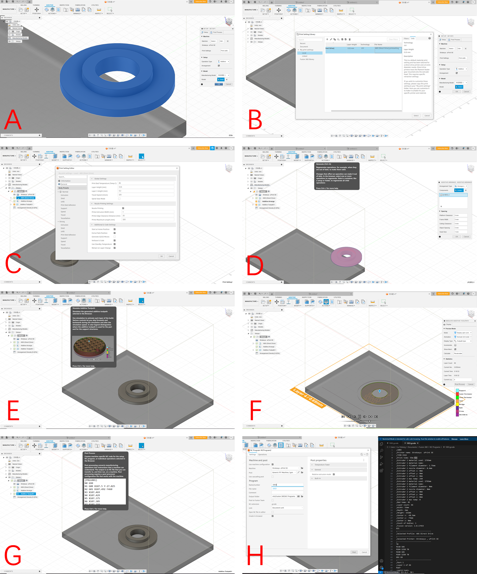
Figure 4. Steps to Generate the Simulation and G-code: A. Select the Parts Needed to Print;
B. Alter the settings for the Printing Processes; C. Page of Print Process Editor;
D. Generate the Printing Simulation; E. Create the Simulation Toolpath; F. Screenshot of the Simulation Video;
G. Post Process to Generate the G-code; H. Save for the G-code File and the Codes in Visual Studio
In this project, the most crucial element from Fusion 360 is the G-code generated specially for our uPrint SE 3D printer based on the assigned printed part. So, we click the Post Process icon at last to generate the G-code and save the code file for simulation in Omniverse afterwards, as Figure 3.1.4 (G) and (H) show. What needs to highlight is that we need to download the Visual Studio application to have the clear view on the G-code generated from Fusion 360 if you are using the Windows system as we are.
Due to the huge volume of the G-code, it can be more than hard to analyze or check the accuracy and the correction of the generated G-code file. To solve this issue, we utilized Visual Studio Code from Microsoft which has many amazing extensions for G-code and CAD. As Figure 5 shows, we recommend four most helpful extensions in VS Code which can be installed from the VS Code extension official, and from the searching bar in VS Code application as well.
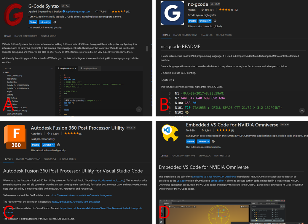
Figure 5. Extensions in Visual Studio Code:
A. G-Code Syntax, B. Nc-gcode,C. Autodesk Fusion 360 Post Processor Utility, D. Embedded VS Code for NVIDIA Omniverse.
G-Code Syntax extension performs excellently in translating the original blank codes into corresponding movements of the tool or the nozzle of 3D printer, so that we can have a better understanding of the generated G-code and check the files with the expected movements of the 3D printer. While sometimes, we may get tired with thousands of bold and blank lines to check with, and nc-gcode extension can help add certain colors to specific types of codes, such as cutting marked red, and tooling marked green, which brings relief and boosts the efficiency of proofreading the codes. Since we may need to do some modifications to some specific steps while reviewing the generated G-code, Autodesk Fusion 360 Post Processor Utility can add some featured functions on CAM post processes. By clicking the color-marked codes, we can choose the replacing codes or type in the modifying lines, which can simplify the work on checking and modifying. Embedded VS Code for NVIDIA Omniverse extension is the pair of the Embedded VS Code for NVIDIA Omniverse extension for NVIDIA Omniverse applications that can be described as the VS Code version of Omniverse's Script Editor. It allows to execute python code, embedded in a local/remote NVIDIA Omniverse application scope, from the VS Code editor and display the results in the OUTPUT panel of the VS Code editor.
2.2 URDF export in SolidWorks
To simplify the manipulation mechanism of 3D printer, we can recognize it as a combination of several simple joints which stand for the movement relationships of each connected parts and axis, as revolute joints (rotating joints) and prismatic joints (translation joints), so that 3D printer becomes a simple robot with the movements of its joints limited. Thanks to Omniverse Isaac Sim application where the robotics can be manipulated and simulation can be achieved, we can directly take the URDF file (unified robotics description format) which is the widely used format for robots [30] to the environment and test the movements with given configurations with the help of self-developed extension, and this process will be introduced in the next section of this chapter.
It is easy operated to create a URDF file based on the present assembly file in SolidWorks 2023 with its plugin named “URDF Exporter”. Exporting the assembly models into URDF format is one of the most basic skills when we deal with robotics building, since the modelling and assembling processes demand powerful CAD software like Inventor and SolidWorks to handle. Based on the exporter plugin [31] with the tutorial [32] from ROS (Robot Operating System), we are able to quickly assign the joint type between the appointed links of our model, showed as Figure 3.2.1 (A. Manage the Property for Each Links and Joints; B. Confirm and Modify the Joint Properties; C. Confirm and Modify the Link Properties.)
A property management page is initially displayed by the exporter in order to configure the URDF Export. First, we need to manually construct the tree and configure each connection. The tool will save the data with the assembly after configuration, which is only done once. We also don't need to take any further action in this manner. Only parts can be selected in SolidWorks if we choose components on the real assembly display rather than the Feature Manager Design Tree. Assemblies that reflect the complete link are more likely to be chosen, thus we will have to choose them from the Design Tree as showed in Figure 6 A.
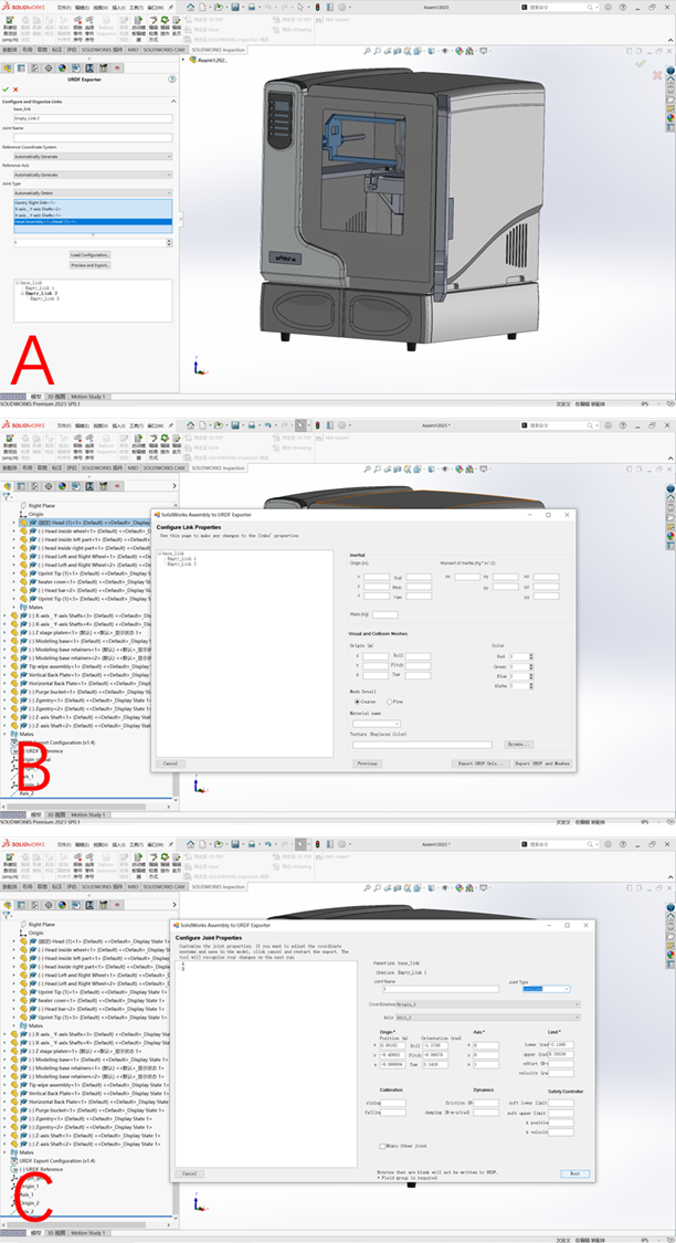
Figure 6. Export a SolidWorks Assembly to URDF
A. Manage the Property for Each Links and Joints; B. Confirm and Modify the Joint Properties; C. Confirm and Modify the Link Properties;
Every link we have introduced is visible in the configuration tree. A junction will be made to the parent link of each child link in the tree. Any link that has already been added can be selected to modify its characteristics. You can remove or add children to a link by right-clicking on it. Links can also be rearranged by dragging and dropping them. A child link will move to take the place of the parent link when the parent link is dragged onto it. The other offspring of the parent link remain under the original parent link. By selecting the green checkbox, you may simply save your setup and go. We can leave without storing the settings changes by clicking the red X symbol.
Click "Preview and Export..." once your URDF is prepared for construction. At this point, the tool will construct coordinate systems or axes if it has been instructed to do so automatically.
2.3 USD file transformation in Omniverse
Nvidia's platform for real-time collaboration, Omniverse, has found widespread use across a range of industries, including visual effects and "digital twin" industrial simulation. Due to the difference of the names of its applications, and the functions of its extensions between Omniverse versions, in this project, we take Omniverse launcher 1.9.8 with the latest version of Isaac Sim (2023.1.0), and Code (2023.1.1) in Windows 10 22H2 operating system, and we installed Visual Studio 2022 for G-code preparation as we mentioned in the previous content.
Note that Omniverse simulation has specific demands for the hardware equipment which may leave huge impact on the efficiency and the display outcome. By combining the system requirements from the introduction pages of each application. In Figure 7, we take our operation computer in 12th Gen Intel® Core™ i7-12700H with 14 cores, 2 \( × \) 16 GB Crucial RAM in DDR5with 4800 MHz, NVIDIA GeForce RTX 3070 Ti GPU (8GB) for laptop, and Samsung SSD 980 Pro storage more than 1024 GB for Omniverse.
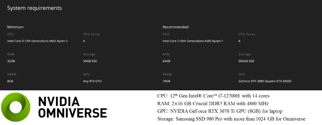
Figure 7. Library Page in Omniverse Launcher with the Computer Configurations
Firstly, we are introducing the USD Composer application, also known as Omniverse Create, which is one of the most frequently used applications in all the modules in the platform. In Create, we are allowed to import all types of CAD files to it and establish the environment as we design, with or without the installed environment elements Omniverse provided. And the main page is showed as Figure 8, with the display of the whole environment in the middle, with the file address below, and the gallery of the properties is on the right.
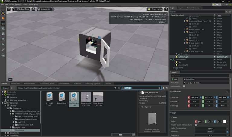
Figure 8. Main Page of USD Composer and Isaac Sim in Omniverse
What we need to highlight is the similarity of the distribution of the function on the main page between traditional CAD application and Omniverse USD Composer. As mechanical engineering students, members in the project hold the greater familiarity with the kind of display page and function menu distribution in CAD software like SolidWorks and Inventor. When turning into Omniverse system, we found that the manipulation menu where the Select, Move, and other basic functions locate, is on the left of the display window. At the same time, on the right is Stage and Layer page where the components and layers of the models reveal. And the Property label is below the Stage page, where we can make quantized adjustments in certain axis to the transform or rotations of one or several selected parts of the model.
Compared with the traditional CAD software, Omniverse Create has its greatest feature lie on the effect of light, which allows us build more realistic environment to simulate the real experiments. And the light control pattern is right under the transform page, where we can alter the distance and the strength of the light.
To establish the lab environment, we need to transfer our CAD files created from Fusion 360 or other CAD applications like SolidWorks, and Inventor, to Universal Scene Description (USD) formation which can be smoothly used throughout all the Omniverse apps. Do pay attention to the assembled models, for they may lose their original constraints while transfer into USD file, which has great relation with the input file formation. We have tested several universal CAD formations, as IGS, STL, STP, SLDASM, SLDPRT and so on, and the most reliable formation for transformation to USD files turns out to be the SLDASM which stands for SolidWorks Assembly. Although, SLDASM formation does have some details missing from the original design or assembly comparing with it showing in SolidWorks, IGS and STL formation lose the material properties and STP file separate the original constraint of assembly. And Figure 9 shows the comparisons among the original display of the 3D printer model in SolidWorks, and the same file which saved in IGS and SLDASM, transferred into USD in Omniverse.
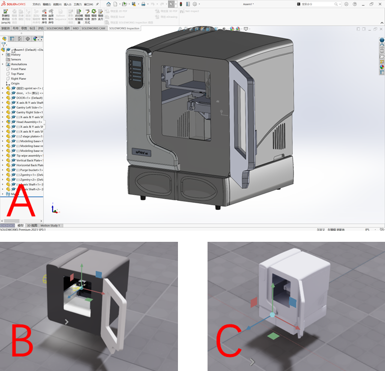
Figure 9. Comparison among A. Original File in SolidWorks, B. SLDASM Formation Transferred in Omniverse, and C. IGS Formation Transferred in Omniverse.
To transfer the original CAD files into USD formation in Omniverse is not difficult at all. As demonstrated in Figure 10, the process begins by activating the CAD extension modules, which can be accessed via the "Window" label in the Main Menu located at the top of the main page (Figure 3.3.4 A). Within these modules, there are multiple extensions, and you can use "CAD" as keywords to search for the required ones, which are named "CAD Converter" and "CAD Converter Core."
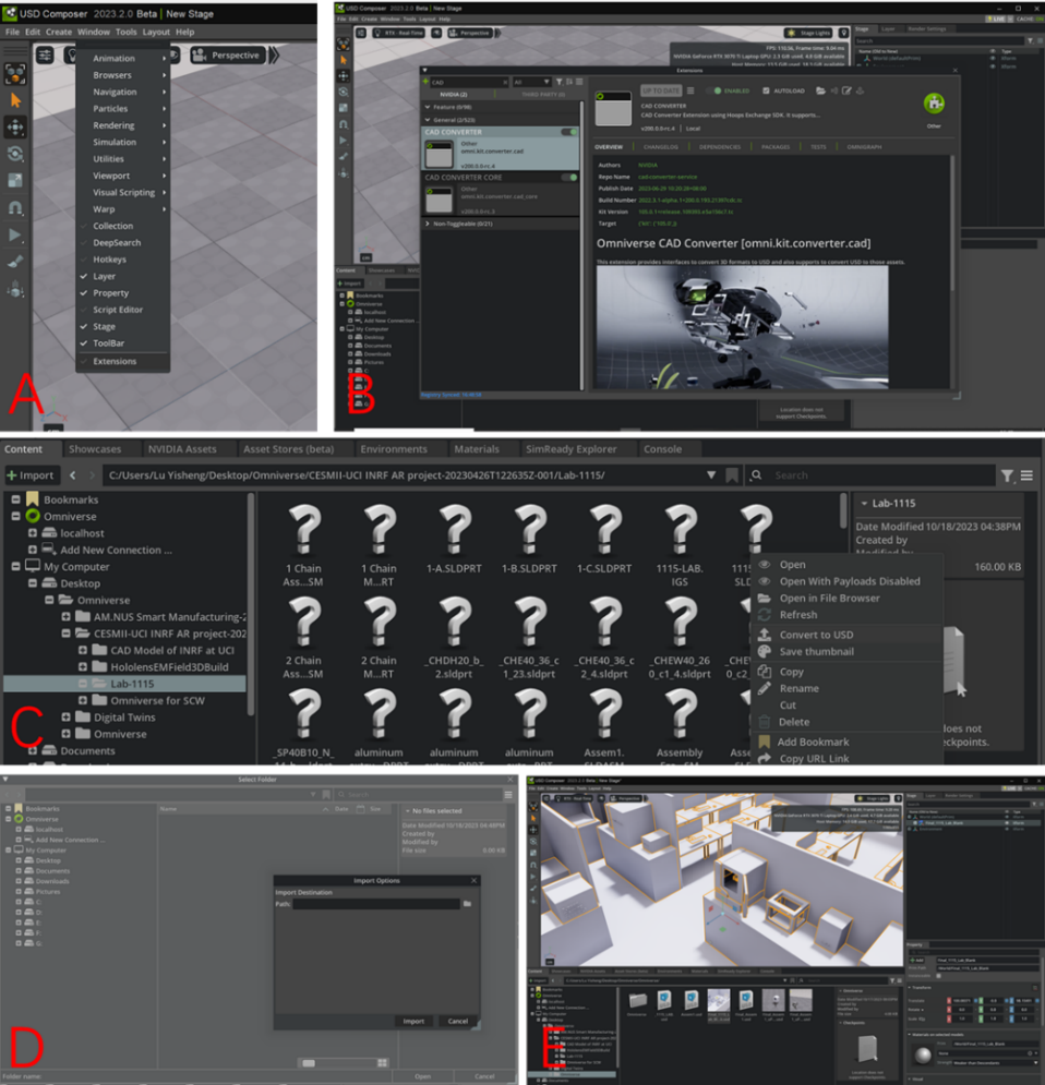
Figure 10. Steps to Transfer CAD Files into USD Formation with Extensions in Omniverse
A. Open Extensions under Windows Label in Main Menu;
B. Search “CAD” as Key Words in Extensions Box, and Enable CAD Extensions with Autoload on
C. Select the CAD files in Content Menu, and Right-click to Convert to USD;
D. Customize the Address for USD Files; E. Drag the USD Files from its Address to the Main Display.
Upon selecting the module, detailed information will appear on the right side of the window, where you can also find the "enable" icon and "autoload" option (Figure 10 B). To make them operational, click on these elements. After successfully enabling the extensions, you'll be able to convert CAD files into USD format. To do this, select the CAD files directly from the address box at the bottom of the main page, right-click on them, and choose the option to convert them into USD files. Additionally, you should assign a new address for the output file before generating it (as shown in Figure 10 C and D). Please note that the time required for Omniverse to read and convert the CAD files may vary depending on the size and complexity of the models. Once the conversion is complete, you can directly drag the USD file from the address box and release to load it into the environment you have created, as illustrated in Figure 10 E. Apart from USD Composer, although Omniverse has Isaac Sim, Code and other useful applications, and several of which are applied in this project, the home page and the instruction of USD covert and input are not to introduce for they share great similarities and nearly the same display, and function distribution. Any exceptions are going to be emphasized in the exact sections later.
It may have issues because the axis directions which Omniverse and CAD applications have may be different. We can use the Transform label from the right of the page to have some quantified adjustments to rotate the axis of the models and have translational move to proper locations in the environment.
Whereas sometimes it would have some problems with the material properties, assigned colors and the assembly constraints of the USD files when compared with the original CAD files. That is mainly resulted from the formation of the original files --- formations like STL will transfer all the details into multiple lines becoming linear expressions which have saved no data for the material details. So, we strongly recommend to use the original CAD files like SLDASM from SolidWorks, and IAM from Autodesk Inventor.
3 Simulation with G-code in Omniverse
In this chapter, we are introducing the method in which we can import the G-code generated by Fusion 360 into the self-developed extensions in Omniverse platform, and manipulate Uprint SE 3D printer, as well as achieve the simulation of the printing processes. There are three main steps to complete a simulation in Omniverse --- firstly, build an extension in Omniverse to manipulate each axis and joint of the 3D printer; secondly, program the extension in VS Code to achieve G-code translation to assigned movements of the axis and joint; at last test the extension with G-code generated from Fusion 360 and compare the accuracy of the toolpath.
3.1 Extension settings in Omniverse
According to the steps we mentioned above, we firstly need to create an extension in which we are able to control the movements of the printer, and later achieve the simulation based on the given G-code. By following the tutorial from NVIDIA Omniverse Isaac Sim [33], we can easily build up the frame of our self-developed extension. Create a folder on your computer where you want Omniverse Isaac Sim to search for user extensions.
Because the innate character of manipulation of the printer lies in the controlling of each axis and joint which shares a great similarity with robotic arm manipulating, we established the environment in Issca Sim application instead of USD Composer to utilize the special designed applications for robotics. Figure 11 A demonstrates the first step to build an extension in Issca Sim, which is to navigate to Isaac Utils label on the top of the page, and then we select “Generate Extension Templates” in the toolbar.
Due to the controlling in specific figures in the movements of the printer components, we select “Configuration Tooling Template”, as Figure 11 B, and then follow with editing the path of the extensions to assigned file, the extension name and its description if necessary. The most crucial settings are showed in Figure 11 C, D, and E navigate to Window label beside Isaac Utils, and select “Extensions” in the toolbar to open the Extensions Manager. Followed with clicking the hamburger icon, which is the setting list in the Extensions Manager, and then “Settings” in the sub-menu to add the path which is the same one we assigned in Figure 4.1.1 B, to the folder created for self-developed extension, we have introduced the new-built extension file to Issca Sim platform, and it is ready for using.
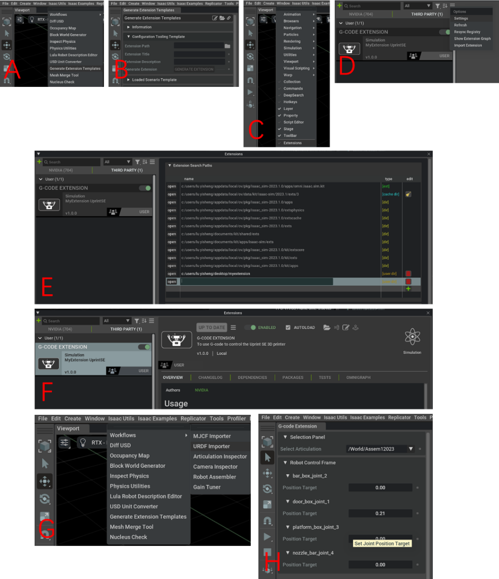
Figure 11. Steps to Create an extension in Omniverse
A. Select “Generate Extension Template” under Isaac Utils Label;
B. Edit the Address for Self-developed Extension under Configuration Tooling Template Label;
C. Select “Extension” under Window Label; D. Go to Setting under the List Icon after Selecting “Third Party”;
E. Click “+” Icon to Add the Paths of the Extension; F. Click and Enable the Extension;
G. Import the URDF File to the Environment; H. Open the Extension after Playing the Time Line
In Figure 11 F, we can find our extension in the Extensions Manager under “Third Party Extensions” and click the open icon to enable it, and as a result our extension appears in the toolbar where we can click as same as the other labels. Now the self-developed extension for robotic configuration is ready for use. Open Isaac Utils label again to select the URDF Importer under Workflows, and add the paths of the URDF file which we exported from SolidWorks in the previous section of this chapter, as Figure 11 G. After the success of importing the URDF file into the environment, we select all the models and click the Start (arrow symbol) on the left of Extension panel, and the extension will automatically detect the joints in the model and turn to the control page like Figure 11 H showed.
3.2 Extension programming in Visual Studio Code
It may sound easy to manipulate the nozzle of 3D printer or robotic arms in digital twin environment, but actually the problem lies on the difference between the printing process and the simulation, and demands specific solution to overcome.
To manipulate a robotic arm, we need to determine the position and rotation (gesture) of each joint and reshape the data into matrices from the very beginning, which combine and represent the exact state of the whole robotic arm. And with applications like ROS and Moveit, we are able to set the start and the end gestures, and the moving time, so the computer may generate the feasible paths in smooth curve if there is no collapse. In Omniverse, the digital twin environment, we can directly take the extensions for ROS and Moveit which are well programmed by NVIDIA official for the data transfer and movement control, and start to set the gestures as we used to do in Moveit. So it is much simpler to integrate the controlling software (ROS and Moveit) with the digital twin system (Omniverse).
However, to integrate the 3D printer into Omniverse, is another different story, due to the lack of official extensions to translate the original code for 3D printer (G-code) or to control the mechanism for nozzle movements. We have to develop an extension to achieve the code transfer and the manipulation, and in the previous sections we have already introduced the detailed processes to develop an extension for joint control. At this section, we are introducing the programs we developed to transfer the G-code into Python (expressed as G-code Parser in the following content) which can be recognized by VS Code and Omniverse.
G-code stands for Geometric Code which is the programming language utilized by CNC (Computer Numerical Control) equipment and G-code is employed to provide instructions to the machine on what actions to take and how to execute specific tasks, guiding the machine regarding where to move, the speed of movement, and the route to follow. In the case of machine tools such as mills or lathes, these commands result in the cutting tool following a predefined toolpath and removing material to achieve the desired shape. Similarly, when it comes to additive manufacturing (3D printing), G-code commands instruct the machine to deposit material layer by layer to construct a precise geometric shape. As Figure 12 shows, a piece of typical G-code commands usually have different capital letters followed by digital numbers, which represents the functions and the data.[34]
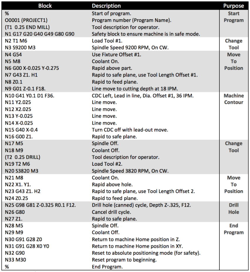
Figure 12. Typical Example of G-code Command Blocks and the Descriptions from Autodesk
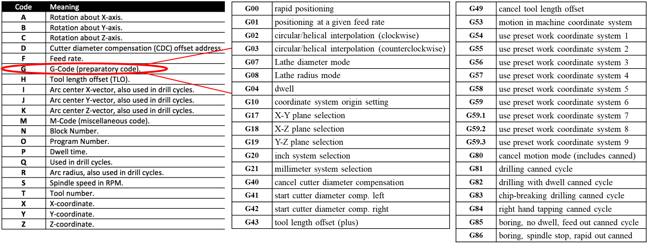
Figure 13. Typical G-code with their common combinations
Because there are multiple types and blocks of G-codes which we are unable to introduce thoroughly in this report, we take the most widely used G-code types with their basic blocks and the details are showed in Figure 13, to have an overall understanding about G-code.[35]
Based on the regular pattern that each capital letter is followed by at least one digital number as a combination in G-code commands, so if we can determine the first letter, this combination which the letter starts with can be classified into a certain category as we showed previously. For example, if the parser receives a combination starting with letter G, the first step for the program should be narrowed down the combination to preparatory code. And it would be much easier to define the meaning of the combination after the first capital letter is verified. The codes in Figure 14 demonstrate the discussion on classification to confirm the common G-code commands. With different numbers following the letters confirmed, the movements are defined with certain meanings, which can be recognized by Omniverse (The whole plugin codes for G-code parser is attached in Appendix).
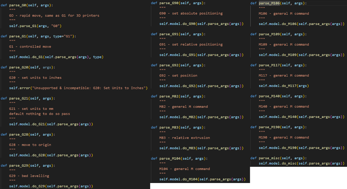
Figure 14. Python Codes for Discussion on Classification of Common G-codes
After success in recognizing the G-code input, we need to confirm the size for building platform before we step forward to simulate the movements. In Figure 15 A, a Python class named BBox which is to be a bounding box representation in 3D space. The constructor takes a dictionary coordinate as its argument, which is expected to contain keys "X", "Y", and "Z", and initializes the BBox object with the minimum and maximum coordinates along the X, Y, and Z axes based on the values provided in the dictionary. Methods for dimension and center calculation lie on that “dx”, “dy”, and “dz” are methods to calculate the differences between the maximum and minimum coordinates along the X, Y, and Z axes, respectively. While “cx”, “cy”, and “cz” are methods to calculate the coordinates of the center of the bounding box along the X, Y, and Z axes, respectively. The extend method takes another coordinates dictionary as an argument and updates the bounding box to extend its boundaries if the provided coordinates are outside the current boundaries. This method is used to expand the bounding box as new coordinates are encountered. To define the string representation of the BBox object, we use string method which returns a formatted string showing the minimum and maximum coordinates along the X, Y, and Z axes. So, we can type in the given parameters of the printer to build up the exact working space in the simulation.
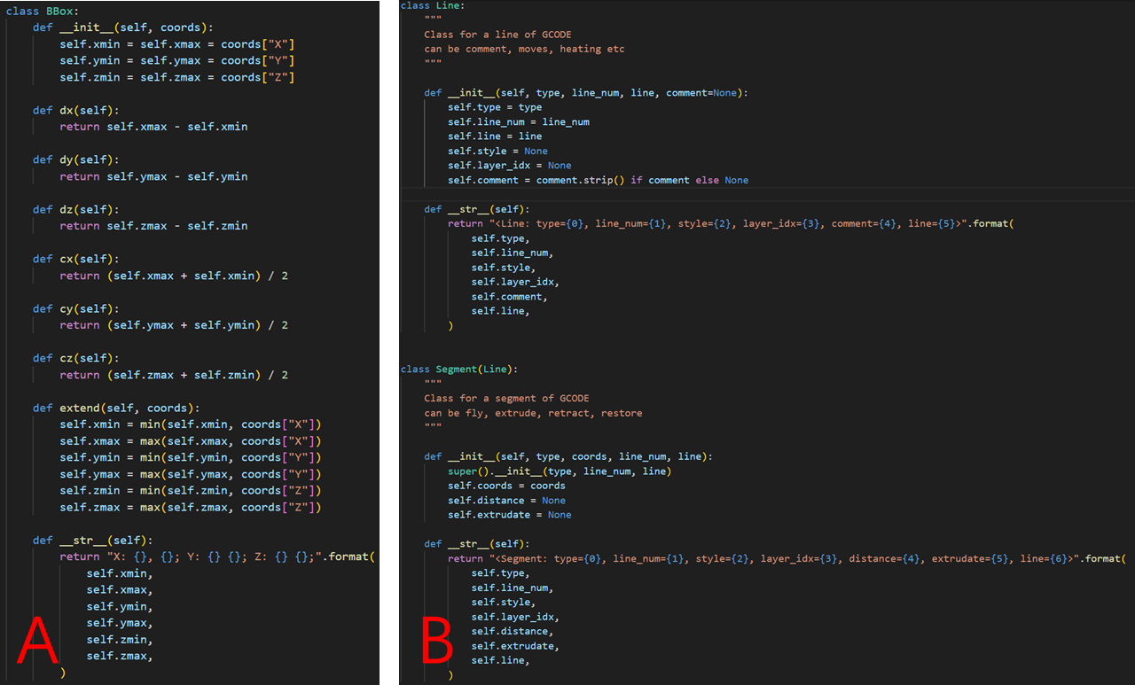
Figure 15. Python Code Class for Platform Settings and Line Drawing:
A. BBox for Bounding Box Representation; B. Line for G-code Line Drawing Representation.
In Figure 15 B, another Python class named Line is representing a line of G-code. There are four parameters in “Constructor”: The type of G-code line, comment, move, heating, etc.; The number of the line in the imported G-code files; The actual content of the GCODE line; “Comment” (optional) acts as an optional comment associated with the G-code lines. The constructor initializes instance variables with these parameters, and also initializes “style” and “layer_idx” to “None”. With the string method applied, the class of codes provides a string representation of “Line” object and returns a formatted string containing information about the type, line number, style, layer index, comment, and the content of the G-code lines.
Based on the practical additive manufacturing processes, we also create “Segment” and “Layer” class, which inherits from the “Line” class, and the former class of codes represents a segment of G-code that can be associated with actions like fly, extrude, retract, or restore. While the latter describes the renewal of the process in the next layer in 3D perspective. Due to the limited content of this report, we are not to analyze these parts in detail, and all the codes are in Appendix.
There is quite an extensive Python class named as “GcodeModel” with a variety of methods, acting as the main functional parts for the whole program and contributing to a comprehensive representation of a G-code model, with methods for handling different G-code commands, manipulating segments, and calculating metrics. And the related codes are attached in Appendix.
It initializes various attributes to store information about the G-code model, including the parser, relative and offset coordinates, flags for relative movement, a list of segments, layers, distances, extrudate, and a bounding box (BBox).
Firstly, writing to file (“write”) provides a method to write the G-code model to a output file. While Comment handling (“add_comment”) adds a comment line to the G-code model. Then the program comes to deal with the different types of G-codes on their categories (discussion on classification) --- “do_G1” handles G1 commands, which represent rapid/controlled moves; “do_G21” handles the G21 command to set units to millimeters; “do_G28” handles the G28 command for moving the nozzle or tool to its origin position; “do_G29” takes the G29 command for bed leveling for changing the layer and thickness; “do_G90” and “do_G91” aim to set absolute and relative coordinates respectively; “do_G92” deals with the G92 command to set the position without moving; “do_M82” and “do_M83” represent M82 and M83 commands to set extrusion to absolute or relative. “do_M104”, “do_M106”, “do_M109”, “do_M117”, “do_M140”, “do_M190” and “do_misc” stand for various unimplemented M commands, which can be found in related G-code manuals; “set_relative” sets the Boolean value for relative or absolute movement; “add_segment” and “insert_segment” adds or inserts a segment to the list of segments; “warn” and “error” provide methods for displaying warning and error messages.
Meanwhile, “GcodeModel” quotes many classes of codes which we have introduced, and makes them functionally integrated with the whole process: “classify_segments” applies intelligence to classify segments based on movement and extrusion; “split_layers” splits the segments into layers based on Z changes; “calc_metrics” calculates various metrics of the model, including distance, extrudate, and bounding box; “post_process” performs post-processing, including classifying segments, splitting layers, and calculating metrics.
The most significant step of this project is how to integrate the G-code parser with the extension we developed in Omniverse with the movements successfully assigned to each joint and link of the 3D printer. There are four joints of different types, as joint_door is a revolute joint and joint_head, joint_bed and joint_X axis are all prismatic joints. We assigned each joint with a specific speed according to the guide book from uPrint SE official website, so by applying one unit of time, we can have a small displacement of a certain joint since speed of each joint differ from each other.
To realize the match to the given G-code file, we made the displacement of each joint correspond to the G-code program, which allows each joint move continuously as the toolpath generated in Fusion 360, as shown in Figure 16.
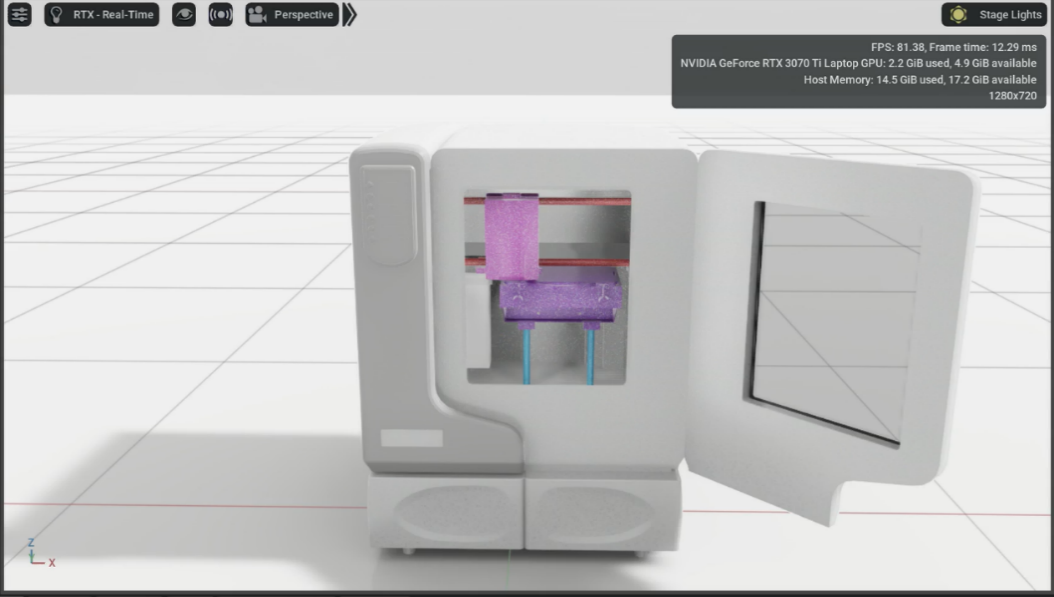
Figure 16. Joint Movements Based on the Generated G-code
To practically examinate the accuracy of the 3D printing simulation we developed in Omniverse, we will use a case study in the next chapter to check each step from the mode building to the simulation of joint displacements.
3.3 Case study: Simulation of Spur gear printing
Spur gears, the most prevalent kind of gear with straight teeth that run parallel to the axis of the gear, plays as one of the most important roles in the mechanical world, quietly conveying motion, and power in a plethora of machines. Consider them the gear family's dependable workhorses, spur gears maintain smooth operation in a variety of devices, including simple clocks and the transmission of your car, and they transfer rotational motion effectively and are simple to manufacture thanks to their simple design. Although spur gear may not be as ostentatious as other gears, they are unquestionably the foundation of many mechanical systems.
In this case testing the function and accuracy of the simulation through our G-code parser integrated extension in Omniverse. We used a spur gear as the sample which was 10 times scaled down from a 400-rpm gear wheel for industrial-use, with its pitch diameter at 732.5 mm, module at 12.2 mm, number of teeth rounded at 60, face width rounded at 18.3 mm, pressure angle in 14.5°, 15Hp, and thickness at 63.5 mm. And the modified parameters are showed in Figure 17.
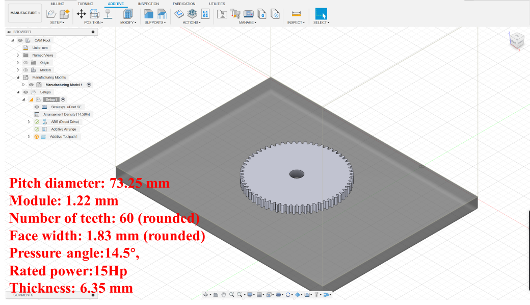
Figure 17. Spur Gear Sample in Fusion 360 with Its Parameters
According to the steps in chapter 3, we imported the CAD model to Fusion 360 and generated the toolpath (showed as Figure 18), based on the environment of uPrint SE 3D printer which we have completed the settings and saved as a pattern in Library, before we continued to Post-process (G-code file generation).The whole toolpath takes 1 hour, 24 minutes and 15 seconds to complete 42 layers with each increasing mostly 0.15 mm in height, and the G-code file had 196 892 lines due to the unavailability of the shortened omission for regular route.
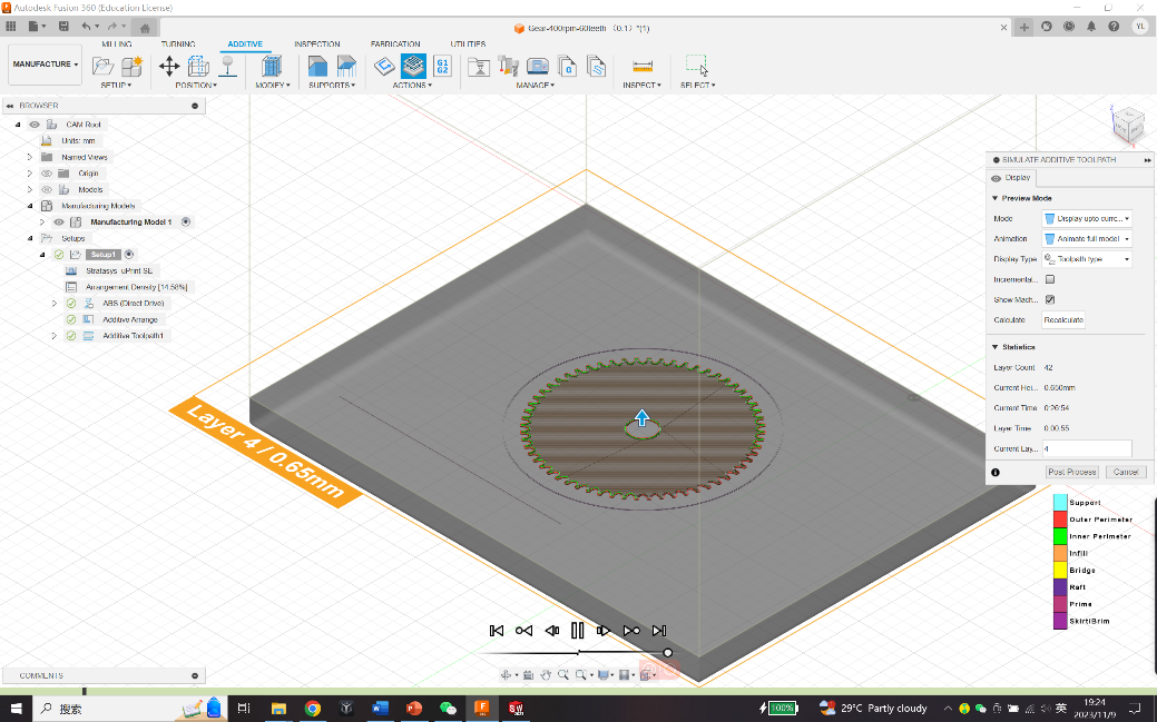
Figure 18. Toolpath Generation of Spur Gear with UPrint SE in Fusion 360
Next, we moved to Omniverse where the simulation took place. By following the instructions which we have mentioned in chapter 4, we succeeded in transferring the uPrint SE printer model file in URDF format which we generated from SolidWorks by assigning the joint-link relationships to the parts, and developing the extension in Omniverse Isaac Sim with the G-code parser which we programmed in VS Code embedded in.
The G-code file of spur gear was loaded in through the self-developed extension, and it may take a while for the G-code parser to read and analyze the G-code lines and sections after the “Run G-Code” button was clicked, as Figure 19 showed.
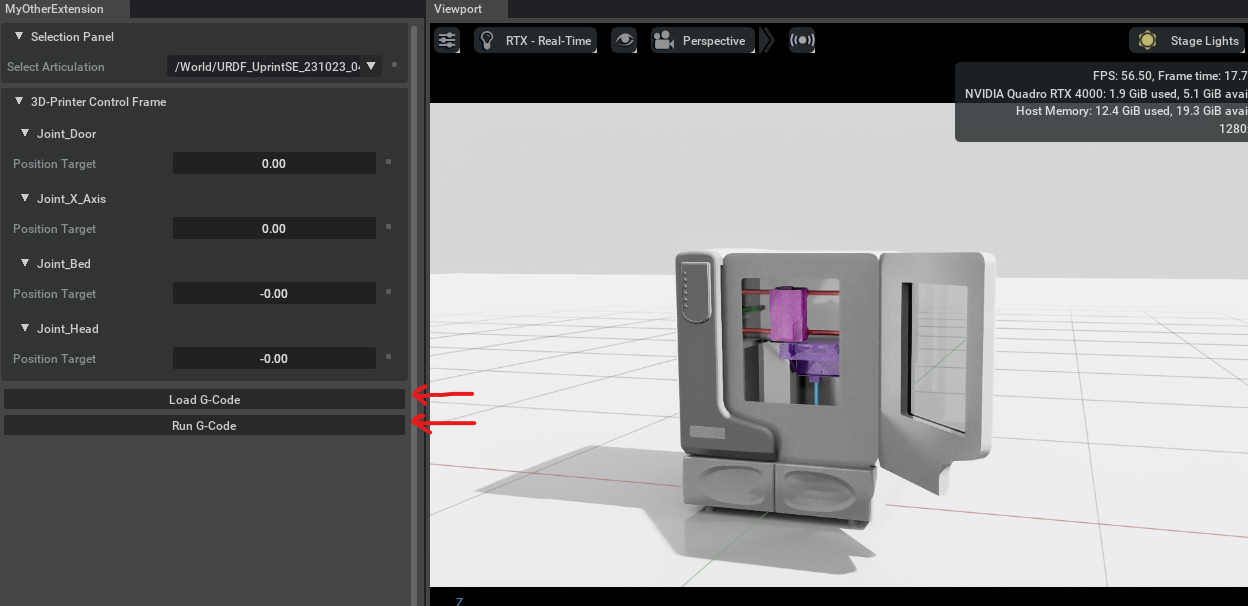
Figure 19. Simulation with Self-developed Extension for G-code in Omniverse
However, we noticed that it may take quite long periods of time to fully analyze the codes due to the huge volume of the G-code file which may consist of millions of lines. And it results from that the codes generated by Fusion 360 represents each single movements in the resolution and printing speed of the typical printer. In one hand, Fusion 360 does carefully work and takes each printing spot into consideration, and in the other hand, simplification of the G-code files is eagerly in needed which could reduce the processing time of loading and analyzing in the extension. By rewriting the G-code file by ourselves, and comparing the time the simplified G-code file took and the original one needed, we found the volume of the file do contribute to the processing time. Therefore, the scope of the future improvement on the extension loading and analyzing lies on the simplification of the imported G-code file.
From enduring perspective, to ensure the compatibility of the self-developed extension on different models of 3D printer, we need to add one more step as an interactive panel displayed when the extension is loaded in Omniverse to let the user type in the important parameters, like working space (BBox), printing speed and its resolution, so that the extension could learn the specific printing environment from different types of 3D printer we use.
4 Conclusions and future work
The future of smart manufacturing and beyond --- The manufacturing industry is undergoing a radical change driven by the rapid development of technology. This change is transforming the fundamental concept of production and the key factors of efficiency, sustainability, and competitiveness. The main force behind this change is the incorporation of Artificial Intelligence (AI) and Data Analytics into the heart of industrial processes, creating a new era of “Smart Manufacturing.” This change also affects many other real-world industries, offering a vision of a more efficient, sustainable, and insights-driven future.
From building the printing models in Fusion 360 with its G-code generated, modifying the codes in Visual Studio Code, and the converting CAD files into USD formations in Omniverse, we marched to the simulation of 3D printing process in Omniverse step by step, and with the creative developments in Digital twin applications.
The use of AI and data analytics in smart manufacturing brings many benefits that change the way production is done. Production lines can be monitored and controlled in real-time, maintenance can be predicted, quality can be optimized, and market demands can be met with agility. The outcome is a manufacturing system that has higher operational efficiency, lower downtime, lower costs, and, most importantly, the ability to deliver better products to consumers.
As this report has illustrated, the use of AI and data analytics in smart manufacturing goes beyond the manufacturing industry, and it provides viable answers for actual industries, each with its own special possibilities and challenges.
Our project is a ground-breaking attempt that combines the fields of artificial intelligence (AI) and data analytics with additive manufacturing (3D printing). Through the use of G-codes customized for Uprint SE 3D printer, we were able to explore the state-of-the-art NVIDIA Omniverse platform. We made great progress in this area with the simulation and virtual environment visualization of the 3D printer's operations.
But the trip doesn't end with simulation. With the help of the Omniverse platform—a precursor to digital twin systems— advancing in the field of augmented reality is more than promising. After being proven in robots and production lines, the idea is currently being used to simulate the actions of 3D printer in real time by coordinating data with cameras placed at crucial angles. And several issues we have come across during the exploration of simulation are eager to be solve, such as to simplify the generated G-code file to increase its readability helping the parser codes in the extension to load more quickly, to develop some operation system for 3D printer similar to ROS and Moveit for robotics which surely will boost the efficiency of integration an manipulation, and to further study on the compatibility of the self-developed extension to fit more 3D printers different in working space, printing speed, and resolution.
Additionally, the potential for predictive analytics, combined with machine learning, is enormously powerful when looking toward the future. Imagine a time when artificial intelligence (AI) and data analytics are fused by post-data analysis from manufacturing processes and trials, enabling accurate estimation of material requirements and the amount of time needed to print a new model. This is the frontier of smart manufacturing, where efficiency has no limits and data transforms into foresight.
The potential applications of this project in the real world are transcending the boundaries of manufacturing into a host of diverse industries. In the next section, we will investigate the creation of a realistic digital twin of the 3D printer, synchronized with real-time data, which has the power to revolutionize manufacturing processes, along with collaborative design in shared virtual environments, and customization and personalization of 3D printed product.
The project of simulating and visualizing the 3D printer using NVIDIA's Omniverse platform has many potential applications in the real-world industries, especially in the field of smart manufacturing. Some of the applications of this project are:
Digital twin is a virtual representation of a physical product or process that can be used to monitor, analyze, and optimize its performance.[36] By using NVIDIA's Omniverse platform, we are expecting to create a realistic and interactive digital twin of the 3D printer, which can be synchronized with the real-time data from the physical device. This can enable the manufacturers to remotely control, troubleshoot, and optimize the 3D printing process, as well as to test different scenarios and parameters without affecting the actual production. Not only in large industrial assembly lines like vehicles or airplane, digital twin could simulate the promising plan for new workflow to reflect the potential flaws and unproper settings with the integration of AI, but also in fabrication of advanced cellular materials, the digital twin could predict and provide the conclusions or printing paths including the dispersion of the powder, the collision of droplets, and so on, with AI learning algorithm and data analytics.
Collaborative design is a process that involves multiple stakeholders working together to create a product or solution that meets their needs and preferences. By using NVIDIA's Omniverse platform, the project can facilitate collaborative design among different users, who can access and modify the same 3D model in a shared virtual environment. This can enhance the communication, creativity, and innovation among the designers, as well as to reduce the time and cost of product development. BMW Group started global rollout of NVIDIA Omniverse in early March, 2023, which achieved the integrated network of each department in production workflow, and used Omniverse to create a overall digital twin thanks to the cloud system.
Customization and personalization are strategies that aim to tailor a product or service to the specific needs and preferences of individual customers. By using NVIDIA's Omniverse platform, the project can enable customization and personalization of 3D printed products, by allowing the customers to interact with and modify the 3D model in a virtual environment before printing. This can increase customer satisfaction, loyalty, and engagement, as well as to create unique and differentiated products. The group can build up sharing files in Nucleus, which is the file manage system embedded in Omniverse, allowing the CAD and USD files to use and edit in different applications and devices freely and simultaneously.
Apart from industrial applications, the achievements of this project can also be utilized in some other fields, like education and training, entertainment, and gaming, as well as further research and development.
Education and training are processes that aim to enhance the knowledge, skills, and competencies of learners or workers. By using NVIDIA's Omniverse platform, the project can provide a realistic and immersive learning experience for students or employees who want to learn about 3D printing or related topics. Even for the deep ocean or some other microscale world which may be create in digital twin environments. They can interact with and manipulate the 3D model in a virtual environment and observe the effects of their actions. This can improve their understanding, retention, and motivation, as well as to reduce the risks and costs of real explorations.
Entertainment and gaming are activities that provide fun, enjoyment, and relaxation to people, and NVIDIA's Omniverse platform is originally designed for that. The project can create a captivating and interactive entertainment or gaming experience for users who want to have fun with 3D printing and other industrial equipment which are strictly limited to the professionals, becoming a real worker to manipulate these robotics arms. They can create and customize their own products and models in a virtual environment and manufacture and print them in a simulated world. This can stimulate their creativity, curiosity, and excitement, as well as to provide them with unique and personalized products.
Further research and development are activities that aim to discover new knowledge, create new products, or improve existing ones. Just as mentioned above, we may be able to replicate the deep ocean or some other microscale world in digital twin environments, and we may get full use of these. By using NVIDIA's Omniverse platform, the project can enable a powerful and flexible research and development platform for researchers or developers who want to explore new possibilities or solutions. For additive manufacturing, they can experiment with different 3D models, parameters, algorithms, etc. in a virtual environment, and evaluate their performance, quality, feasibility, etc. This can accelerate the innovation process, as well as to generate new insights and outcomes.their solid emotional and financial supports, as well as the resilience they instilled in me. You have always been there for me.
References
[1]. Buchmeister, B., Palcic, I., & Ojstersek, R. (2019). Artificial intelligence in manufacturing companies and broader: An overview. In B. Katalinic (Ed.), DAAAM International Scientific Book (1st ed., Vol. 18, pp. 081–098). DAAAM International Vienna. https://doi.org/10.2507/daaam.scibook.2019.07
[2]. Zheng, P., Xu, H., Li, Y., & Yang, G. (2018). Smart manufacturing systems for Industry 4.0: Conceptual framework, scenarios, and future perspectives. Frontiers in Mechanical Engineering, 13(2), 137–150. https://doi.org/10.1007/s11465-018-0499-5
[3]. Wang, B., Tao, F., Fang, X., Liu, C., Liu, Y., & Freiheit, T. (2021). Smart manufacturing and intelligent manufacturing: A comparative review. Engineering, 7(6), 738–757. https://doi.org/10.1016/j.eng.2020.07.017
[4]. Davis, J., Asokan, S., & McLoughlin, J. (2015). Smart manufacturing. Annual Review of Chemical and Biomolecular Engineering, 6(1), 141–160. https://doi.org/10.1146/annurev-chembioeng-061114-123255
[5]. Zhao, Y., Gong, S., Gao, X., Ai, W., & Zhu, S.-C. (2022). VRKitchen2.0-IndoorKit: A tutorial for augmented indoor scene building in Omniverse. arXiv. https://doi.org/10.48550/arXiv.2206.11887
[6]. Kelleher, J. D., Namee, B. M., & D’Arcy, A. (2020). Fundamentals of machine learning for predictive data analytics: Algorithms, worked examples, and case studies (2nd ed.). MIT Press.
[7]. Tran, K. P. (2021). Artificial intelligence for smart manufacturing: Methods and applications. Sensors, 21(16), Article 16. https://doi.org/10.3390/s21165584
[8]. Nguyen, H. D., Tran, K. P., Zeng, X., Koehl, L., Castagliola, P., & Bruniaux, P. (2019). Industrial Internet of Things, big data, and artificial intelligence in the smart factory: A survey and perspective. In ISSAT International Conference on Data Science in Business, Finance and Industry (pp. 72–76). Da Nang, Vietnam. https://hal.science/hal-02268119
[9]. He, Z., Tran, K. P., Thomassey, S., Zeng, X., Xu, J., & Yi, C. (2022). Multi-objective optimization of the textile manufacturing process using deep-Q-network based multi-agent reinforcement learning. Journal of Manufacturing Systems, 62, 939–949. https://doi.org/10.1016/j.jmsy.2021.03.017
[10]. Huong, T. T., Nguyen, T. T., & Tran, T. H. (2021). Detecting cyberattacks using anomaly detection in industrial control systems: A Federated Learning approach. Computers in Industry, 132, Article 103509. https://doi.org/10.1016/j.compind.2021.103509
[11]. Frank, A. G., Dalenogare, L. S., & Ayala, N. F. (2019). Industry 4.0 technologies: Implementation patterns in manufacturing companies. International Journal of Production Economics, 210, 15–26. https://doi.org/10.1016/j.ijpe.2019.01.004
[12]. Alcácer, V., & Cruz-Machado, V. (2019). Scanning the Industry 4.0: A literature review on technologies for manufacturing systems. Engineering Science and Technology, an International Journal, 22(3), 899–919. https://doi.org/10.1016/j.jestch.2019.01.006
[13]. Lee, J., Singh, J., Azamfar, M., & Pandhare, V. (2020). Industrial AI and predictive analytics for smart manufacturing systems. In M. Soroush, M. Baldea, & T. F. Edgar (Eds.), Smart Manufacturing (pp. 213–244). Elsevier. https://doi.org/10.1016/B978-0-12-820027-8.00008-3
[14]. My, C. A. (2021). The role of big data analytics and AI in smart manufacturing: An overview. In R. Kumar, N. H. Quang, V. Kumar Solanki, M. Cardona, & P. K. Pattnaik (Eds.), Research in Intelligent and Computing in Engineering (pp. 911–921). Springer. https://doi.org/10.1007/978-981-15-7527-3_87
[15]. NVIDIA. (n.d.). NVIDIA Omniverse. Retrieved October 14, 2023, from https://www.nvidia.com/en-sg/omniverse/
[16]. NVIDIA. (n.d.). Omniverse USD Composer App. Retrieved October 14, 2023, from https://www.nvidia.com/en-sg/omniverse/apps/usd-composer/
[17]. SpringerLink. (n.d.). Leveraging NVIDIA Omniverse for In Situ Visualization. Retrieved October 14, 2023, from https://link.springer.com/chapter/10.1007/978-3-030-34356-9_48
[18]. Wesselhöft, M., Braun, P., & Kreutzfeldt, J. (2023). Comparing continuous single-agent reinforcement learning controls in a simulated logistic environment using NVIDIA Omniverse. Logistics Journal Proceedings, 2023(1). https://doi.org/10.2195/lj_proc_wesselhoeft_en_202310_01
[19]. Zhao, H. (2023). 3D modeling of factory scenarios for 5G evaluations. Retrieved October 14, 2023, from https://urn.kb.se/resolve?urn=urn:nbn:se:uu:diva-511243
[20]. Isoaho, J. (n.d.). Creating digital twin of electric vehicle battery. Retrieved October 14, 2023, from http://www.theseus.fi/handle/10024/806153
[21]. Wikipedia contributors. (2023, August 9). Fusion 360. Wikipedia, The Free Encyclopedia. Retrieved October 14, 2023, from https://en.wikipedia.org/w/index.php?title=Fusion_360&oldid=1169419188
[22]. Stratasys. (n.d.). uPrint | Stratasys™ support center. Retrieved October 14, 2023, from https://support.stratasys.com/en/printers/fdm-legacy/uprint
[23]. Popescu, D., Zapciu, A., Amza, C., Baciu, F., & Marinescu, R. (2018). FDM process parameters influence over the mechanical properties of polymer specimens: A review. Polymer Testing, 69, 157–166. https://doi.org/10.1016/j.polymertesting.2018.05.020
[24]. Apro, K. (2008). Secrets of 5-axis machining. Industrial Press Inc. ISBN 0-8311-3375-9. Available at https://books.google.com.sg/books?hl=en&lr=&id=Ws228Aht0bcC&oi=fnd&pg=PA13&dq=+Karlo+Apro+(2008).+Secrets+of+5-Axis+Machining.+Industrial+Press+Inc.+ISBN+0-8311-3375-9.&ots=7HAFmMUSgR&sig=a4dGrQYTTCygD4Sp4VjKrZnopzw&redir_esc=y#v=onepage&q&f=false
[25]. Latif, K., Adam, A., Yusof, Y., & Kadir, A. Z. A. (2021). A review of G code, STEP, STEP-NC, and open architecture control technologies based embedded CNC systems. International Journal of Advanced Manufacturing Technology, 114(9), 2549–2566. https://doi.org/10.1007/s00170-021-06741-z
[26]. Microsoft. (n.d.). Visual Studio Code - Code Editing. Redefined. Retrieved October 20, 2023, from https://code.visualstudio.com/
[27]. Applied Engineering Design. (n.d.). G-Code syntax - Visual Studio Marketplace. Retrieved October 20, 2023, from https://marketplace.visualstudio.com/items?itemName=appliedengdesign.vscode-gcode-syntax
[28]. Timmis, H. (2021). Modeling with Fusion 360. In Practical Arduino Engineering: End to End Development with the Arduino, Fusion 360, 3D Printing, and Eagle (pp. 57–127). Apress. https://doi.org/10.1007/978-1-4842-6852-0_3
[29]. Iancu, C., Iancu, D., & Stăncioiu, A. (2010). From CAD model to 3D print via ‘STL’ file format: MODELUL CAD IMPRIMAT 3D PRIN FORMATUL STL. Fiabilitate și Durabilitate / Reliability and Durability, 1, 73–80.
[30]. Formant. (n.d.). URDF. Retrieved November 7, 2023, from https://formant.io/urdf/
[31]. ROS Wiki. (n.d.). sw_urdf_exporter - ROS Wiki. Retrieved November 7, 2023, from http://wiki.ros.org/sw_urdf_exporter
[32]. ROS Wiki. (n.d.). sw_urdf_exporter/Tutorials/Export an Assembly - ROS Wiki. Retrieved November 7, 2023, from http://wiki.ros.org/sw_urdf_exporter/Tutorials/Export%20an%20Assembly
[33]. NVIDIA. (n.d.). Isaac Sim workflows — Omniverse IsaacSim latest documentation. Retrieved November 2, 2023, from https://docs.omniverse.nvidia.com/isaacsim/latest/introductory_tutorials/tutorial_intro_workflows.html#isaac-sim-extension-workflow
[34]. Deans, M. (n.d.). G-Code for CNC programming. Fusion 360 Blog. Retrieved November 7, 2023, from https://www.autodesk.com/products/fusion-360/blog/cnc-programming-fundamentals-g-code/
[35]. Sherline Products. (n.d.). G- and M-Codes for CNC. Retrieved November 7, 2023, from https://www.sherline.com/g-code/
[36]. Ghahramani, M., Qiao, Y., Zhou, M. C., O’Hagan, A., & Sweeney, J. (2020). AI-based modeling and data-driven evaluation for smart manufacturing processes. IEEE CAA Journal of Automatica Sinica, 7(4), 1026–1037. https://doi.org/10.1109/JAS.2020.1003114
Cite this article
Lu,Y. (2024). Simulation of 3D printing processes with G-code in Omniverse. Advances in Engineering Innovation,10,1-19.
Data availability
The datasets used and/or analyzed during the current study will be available from the authors upon reasonable request.
Disclaimer/Publisher's Note
The statements, opinions and data contained in all publications are solely those of the individual author(s) and contributor(s) and not of EWA Publishing and/or the editor(s). EWA Publishing and/or the editor(s) disclaim responsibility for any injury to people or property resulting from any ideas, methods, instructions or products referred to in the content.
About volume
Journal:Advances in Engineering Innovation
© 2024 by the author(s). Licensee EWA Publishing, Oxford, UK. This article is an open access article distributed under the terms and
conditions of the Creative Commons Attribution (CC BY) license. Authors who
publish this series agree to the following terms:
1. Authors retain copyright and grant the series right of first publication with the work simultaneously licensed under a Creative Commons
Attribution License that allows others to share the work with an acknowledgment of the work's authorship and initial publication in this
series.
2. Authors are able to enter into separate, additional contractual arrangements for the non-exclusive distribution of the series's published
version of the work (e.g., post it to an institutional repository or publish it in a book), with an acknowledgment of its initial
publication in this series.
3. Authors are permitted and encouraged to post their work online (e.g., in institutional repositories or on their website) prior to and
during the submission process, as it can lead to productive exchanges, as well as earlier and greater citation of published work (See
Open access policy for details).
References
[1]. Buchmeister, B., Palcic, I., & Ojstersek, R. (2019). Artificial intelligence in manufacturing companies and broader: An overview. In B. Katalinic (Ed.), DAAAM International Scientific Book (1st ed., Vol. 18, pp. 081–098). DAAAM International Vienna. https://doi.org/10.2507/daaam.scibook.2019.07
[2]. Zheng, P., Xu, H., Li, Y., & Yang, G. (2018). Smart manufacturing systems for Industry 4.0: Conceptual framework, scenarios, and future perspectives. Frontiers in Mechanical Engineering, 13(2), 137–150. https://doi.org/10.1007/s11465-018-0499-5
[3]. Wang, B., Tao, F., Fang, X., Liu, C., Liu, Y., & Freiheit, T. (2021). Smart manufacturing and intelligent manufacturing: A comparative review. Engineering, 7(6), 738–757. https://doi.org/10.1016/j.eng.2020.07.017
[4]. Davis, J., Asokan, S., & McLoughlin, J. (2015). Smart manufacturing. Annual Review of Chemical and Biomolecular Engineering, 6(1), 141–160. https://doi.org/10.1146/annurev-chembioeng-061114-123255
[5]. Zhao, Y., Gong, S., Gao, X., Ai, W., & Zhu, S.-C. (2022). VRKitchen2.0-IndoorKit: A tutorial for augmented indoor scene building in Omniverse. arXiv. https://doi.org/10.48550/arXiv.2206.11887
[6]. Kelleher, J. D., Namee, B. M., & D’Arcy, A. (2020). Fundamentals of machine learning for predictive data analytics: Algorithms, worked examples, and case studies (2nd ed.). MIT Press.
[7]. Tran, K. P. (2021). Artificial intelligence for smart manufacturing: Methods and applications. Sensors, 21(16), Article 16. https://doi.org/10.3390/s21165584
[8]. Nguyen, H. D., Tran, K. P., Zeng, X., Koehl, L., Castagliola, P., & Bruniaux, P. (2019). Industrial Internet of Things, big data, and artificial intelligence in the smart factory: A survey and perspective. In ISSAT International Conference on Data Science in Business, Finance and Industry (pp. 72–76). Da Nang, Vietnam. https://hal.science/hal-02268119
[9]. He, Z., Tran, K. P., Thomassey, S., Zeng, X., Xu, J., & Yi, C. (2022). Multi-objective optimization of the textile manufacturing process using deep-Q-network based multi-agent reinforcement learning. Journal of Manufacturing Systems, 62, 939–949. https://doi.org/10.1016/j.jmsy.2021.03.017
[10]. Huong, T. T., Nguyen, T. T., & Tran, T. H. (2021). Detecting cyberattacks using anomaly detection in industrial control systems: A Federated Learning approach. Computers in Industry, 132, Article 103509. https://doi.org/10.1016/j.compind.2021.103509
[11]. Frank, A. G., Dalenogare, L. S., & Ayala, N. F. (2019). Industry 4.0 technologies: Implementation patterns in manufacturing companies. International Journal of Production Economics, 210, 15–26. https://doi.org/10.1016/j.ijpe.2019.01.004
[12]. Alcácer, V., & Cruz-Machado, V. (2019). Scanning the Industry 4.0: A literature review on technologies for manufacturing systems. Engineering Science and Technology, an International Journal, 22(3), 899–919. https://doi.org/10.1016/j.jestch.2019.01.006
[13]. Lee, J., Singh, J., Azamfar, M., & Pandhare, V. (2020). Industrial AI and predictive analytics for smart manufacturing systems. In M. Soroush, M. Baldea, & T. F. Edgar (Eds.), Smart Manufacturing (pp. 213–244). Elsevier. https://doi.org/10.1016/B978-0-12-820027-8.00008-3
[14]. My, C. A. (2021). The role of big data analytics and AI in smart manufacturing: An overview. In R. Kumar, N. H. Quang, V. Kumar Solanki, M. Cardona, & P. K. Pattnaik (Eds.), Research in Intelligent and Computing in Engineering (pp. 911–921). Springer. https://doi.org/10.1007/978-981-15-7527-3_87
[15]. NVIDIA. (n.d.). NVIDIA Omniverse. Retrieved October 14, 2023, from https://www.nvidia.com/en-sg/omniverse/
[16]. NVIDIA. (n.d.). Omniverse USD Composer App. Retrieved October 14, 2023, from https://www.nvidia.com/en-sg/omniverse/apps/usd-composer/
[17]. SpringerLink. (n.d.). Leveraging NVIDIA Omniverse for In Situ Visualization. Retrieved October 14, 2023, from https://link.springer.com/chapter/10.1007/978-3-030-34356-9_48
[18]. Wesselhöft, M., Braun, P., & Kreutzfeldt, J. (2023). Comparing continuous single-agent reinforcement learning controls in a simulated logistic environment using NVIDIA Omniverse. Logistics Journal Proceedings, 2023(1). https://doi.org/10.2195/lj_proc_wesselhoeft_en_202310_01
[19]. Zhao, H. (2023). 3D modeling of factory scenarios for 5G evaluations. Retrieved October 14, 2023, from https://urn.kb.se/resolve?urn=urn:nbn:se:uu:diva-511243
[20]. Isoaho, J. (n.d.). Creating digital twin of electric vehicle battery. Retrieved October 14, 2023, from http://www.theseus.fi/handle/10024/806153
[21]. Wikipedia contributors. (2023, August 9). Fusion 360. Wikipedia, The Free Encyclopedia. Retrieved October 14, 2023, from https://en.wikipedia.org/w/index.php?title=Fusion_360&oldid=1169419188
[22]. Stratasys. (n.d.). uPrint | Stratasys™ support center. Retrieved October 14, 2023, from https://support.stratasys.com/en/printers/fdm-legacy/uprint
[23]. Popescu, D., Zapciu, A., Amza, C., Baciu, F., & Marinescu, R. (2018). FDM process parameters influence over the mechanical properties of polymer specimens: A review. Polymer Testing, 69, 157–166. https://doi.org/10.1016/j.polymertesting.2018.05.020
[24]. Apro, K. (2008). Secrets of 5-axis machining. Industrial Press Inc. ISBN 0-8311-3375-9. Available at https://books.google.com.sg/books?hl=en&lr=&id=Ws228Aht0bcC&oi=fnd&pg=PA13&dq=+Karlo+Apro+(2008).+Secrets+of+5-Axis+Machining.+Industrial+Press+Inc.+ISBN+0-8311-3375-9.&ots=7HAFmMUSgR&sig=a4dGrQYTTCygD4Sp4VjKrZnopzw&redir_esc=y#v=onepage&q&f=false
[25]. Latif, K., Adam, A., Yusof, Y., & Kadir, A. Z. A. (2021). A review of G code, STEP, STEP-NC, and open architecture control technologies based embedded CNC systems. International Journal of Advanced Manufacturing Technology, 114(9), 2549–2566. https://doi.org/10.1007/s00170-021-06741-z
[26]. Microsoft. (n.d.). Visual Studio Code - Code Editing. Redefined. Retrieved October 20, 2023, from https://code.visualstudio.com/
[27]. Applied Engineering Design. (n.d.). G-Code syntax - Visual Studio Marketplace. Retrieved October 20, 2023, from https://marketplace.visualstudio.com/items?itemName=appliedengdesign.vscode-gcode-syntax
[28]. Timmis, H. (2021). Modeling with Fusion 360. In Practical Arduino Engineering: End to End Development with the Arduino, Fusion 360, 3D Printing, and Eagle (pp. 57–127). Apress. https://doi.org/10.1007/978-1-4842-6852-0_3
[29]. Iancu, C., Iancu, D., & Stăncioiu, A. (2010). From CAD model to 3D print via ‘STL’ file format: MODELUL CAD IMPRIMAT 3D PRIN FORMATUL STL. Fiabilitate și Durabilitate / Reliability and Durability, 1, 73–80.
[30]. Formant. (n.d.). URDF. Retrieved November 7, 2023, from https://formant.io/urdf/
[31]. ROS Wiki. (n.d.). sw_urdf_exporter - ROS Wiki. Retrieved November 7, 2023, from http://wiki.ros.org/sw_urdf_exporter
[32]. ROS Wiki. (n.d.). sw_urdf_exporter/Tutorials/Export an Assembly - ROS Wiki. Retrieved November 7, 2023, from http://wiki.ros.org/sw_urdf_exporter/Tutorials/Export%20an%20Assembly
[33]. NVIDIA. (n.d.). Isaac Sim workflows — Omniverse IsaacSim latest documentation. Retrieved November 2, 2023, from https://docs.omniverse.nvidia.com/isaacsim/latest/introductory_tutorials/tutorial_intro_workflows.html#isaac-sim-extension-workflow
[34]. Deans, M. (n.d.). G-Code for CNC programming. Fusion 360 Blog. Retrieved November 7, 2023, from https://www.autodesk.com/products/fusion-360/blog/cnc-programming-fundamentals-g-code/
[35]. Sherline Products. (n.d.). G- and M-Codes for CNC. Retrieved November 7, 2023, from https://www.sherline.com/g-code/
[36]. Ghahramani, M., Qiao, Y., Zhou, M. C., O’Hagan, A., & Sweeney, J. (2020). AI-based modeling and data-driven evaluation for smart manufacturing processes. IEEE CAA Journal of Automatica Sinica, 7(4), 1026–1037. https://doi.org/10.1109/JAS.2020.1003114