


1. Introduction
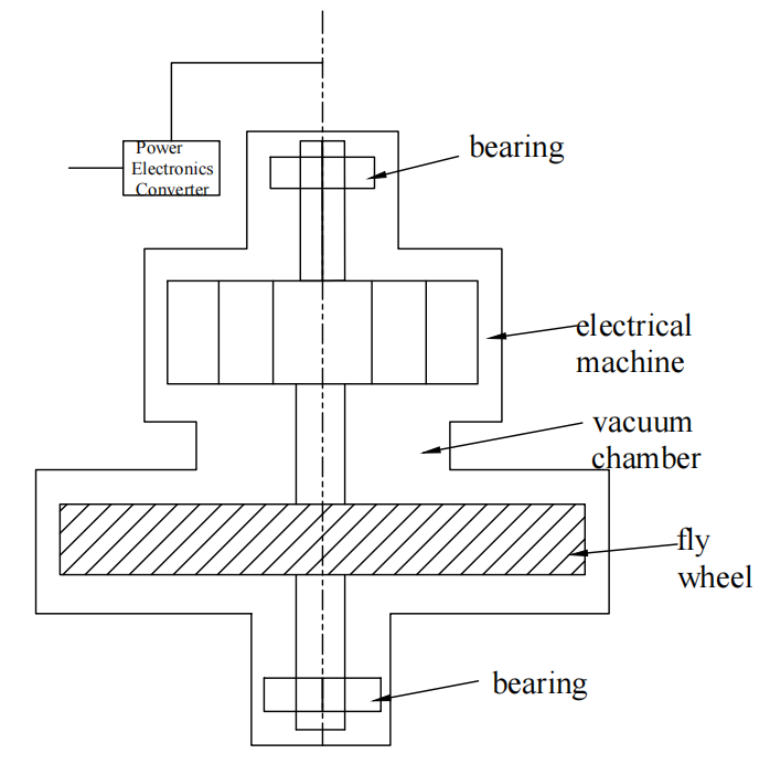
As an emerging physical energy storage technology, flywheel energy storage primarily consists of a flywheel rotor, bearing system, motor system, vacuum and cooling systems, and power converter, as shown in Figure 1 [1]. Its basic principle is to store energy through the conversion between mechanical energy and electrical energy by means of a motor. Due to advantages such as high instantaneous power output and fast response speed, it has been widely applied in fields such as aerospace, marine propulsion systems, industrial and Uninterruptible Power Supplies (UPS), and grid frequency regulation. Pi [2] systematically analyzed the energy storage capacity and power characteristics of flywheel energy storage systems, concluding that a single unit can achieve an energy storage capacity ranging from 0.5 to 100 kW∙h and a power output of 2 to 3000 kW.
At present, research on flywheel energy storage systems at home and abroad mainly focuses on composite material flywheel rotors, disturbance-resistant control systems, safety management of flywheel energy storage, magnetic suspension bearings, and high-speed motor design. Among these, the material and structural design of the flywheel rotor—key factors influencing both energy storage density and safety factor—have long been a central focus for researchers worldwide. From the perspective of flywheel rotor materials, rotors are generally categorized into two types: metallic flywheels and composite material flywheels. This paper reviews research on flywheel rotor materials over the past fifteen years, with particular attention to the performance advantages of composite and metallic materials, as well as the key aspects of structural simulation and analysis for different materials.
As an efficient and environmentally friendly electric energy storage device, the flywheel energy storage system is primarily composed of five major modules: the flywheel rotor, bearing system, motor/generator, power electronic converter, and vacuum enclosure. Among these, the flywheel rotor is the physical medium for energy storage; through high-speed rotation, it converts electrical energy into mechanical kinetic energy. The bearing system—typically magnetic or superconducting bearings—supports the rotor and reduces frictional losses. The motor/generator integrates bidirectional conversion functions, enabling two-way transformation between electrical and mechanical energy. The power electronic converter regulates the electrical parameters of energy input and output. The vacuum enclosure provides a low-resistance operating environment for the rotor, reducing aerodynamic drag. The working principle can be summarized as follows: during charging, electrical energy from the grid drives the motor via the power electronic converter, accelerating the rotor to a high-speed state of tens of thousands of revolutions per minute, thereby converting electrical energy into stored rotational kinetic energy. During discharging, the high-speed rotor transfers kinetic energy to the generator, which converts it back into electrical energy and feeds it into the grid or load through the converter.
Within the entire system, the rotor is undoubtedly the “heart” of the mechanism. As the direct carrier of stored energy, its mass distribution, material properties, geometric shape, and rotational stability directly influence key performance metrics: energy density (which is positively correlated with rotor mass and the square of angular velocity), conversion efficiency (limited by bearing losses, air drag, and electromagnetic losses), service life (determined by fatigue resistance and thermal management), and safety (dependent on suppressing vibration and deformation at high speeds). If the rotor is poorly designed or the material performance is inadequate, it can result in increased energy loss, uncontrolled speed fluctuations, or even structural failure—severely compromising overall system performance.
In view of this, the present study focuses on key scientific issues related to flywheel energy storage rotors and conducts in-depth research in two main areas: (1) multi-objective optimization of rotor materials, exploring the development and processing of novel composite materials—such as carbon fiber-reinforced polymers and metal matrix composites—that offer a combination of high specific strength, low eddy current loss, and fatigue resistance; and (2) innovative rotor structural design, employing topology optimization, shape refinement, and multi-physics coupling simulations to optimize mass distribution, support stiffness, and aerodynamic profile. These efforts aim to enhance energy storage density while reducing operational losses, thus providing theoretical and technical support for the engineering application of highly reliable, long-lifespan flywheel energy storage systems.
2. Mechanical properties of flywheel rotor materials
Due to the generally anisotropic nature of composite materials, their mechanical behavior is relatively complex. This leads to internal structural non-uniformity, and properties such as strength, stiffness, and coefficient of thermal expansion vary with direction. Therefore, the design and analysis of composite material rotors must differ fundamentally from those of metallic rotors. To analyze the differences between flywheel rotors made from various materials, Ma et al. [3] compared the energy storage density and total energy capacity of flywheel rotors composed of titanium alloy, 4340 alloy steel, and epoxy resin-carbon fiber composite. Under identical rotational speed and geometric dimensions, they examined the internal stress and deformation characteristics of each material during operation. Finite element analysis showed that the epoxy resin-carbon fiber composite rotor could withstand the highest rotational speed, exhibited the highest energy storage density, and had the lowest internal stress and deformation. The titanium alloy rotor demonstrated the highest total energy storage capacity. Although the 4340 alloy steel rotor could also achieve relatively high energy capacity, it exhibited significantly greater internal stress and deformation. These findings suggest that research on composite flywheel rotors primarily focuses on enhancing specific energy and reducing manufacturing costs. The performance parameters of typical composite flywheel materials are presented in Table 1.
|
Material type |
(GPa) |
Density(×10³ kg/m³) |
energy density (Wh/kg) |
|
carbon fiber T-1000 |
10.0 |
1.78 |
945.7 |
|
carbon fiber T-700 |
7.0 |
1.78 |
662.0 |
|
T700/5028 epoxy resin |
7.2 |
1.80 |
580~650 |
|
High-tension wound carbon fiber |
6.8~7.5 |
1.75~1.82 |
44.5~50 |
|
Three-ring interference carbon fiber |
6.5~7.2 |
1.76~1.80 |
40~129 |
|
T300 carbon fiber |
3.5 |
1.76 |
134~306 |
|
M40J carbon fiber |
4.4 |
1.77 |
150~280 |
|
Kevlar fiber |
3.8 |
1.45 |
441.1 |
|
S fiberglass |
4.8 |
2.52 |
320.6 |
|
E fiberglass |
3.5 |
2.54 |
231.9 |
In the field of high-speed flywheel energy storage, composite material flywheel rotors, due to their excellent specific strength and modulus characteristics, can achieve a rotational speed increase of 20% to 40% compared to traditional metal rotors. However, the higher rotational speeds introduce additional risks and technical challenges, particularly uneven stress distribution within the rotor that can cause damage and delamination, thereby limiting the maximum achievable speed. Against this background, to further understand the mechanical properties of composite materials, Song et al. [4] established a mechanical model of composite material energy storage flywheels based on finite element theory. They conducted tensile tests on carbon fiber composite rings of varying thicknesses and ring radii. Their results showed that carbon fiber composites exhibit significant thickness and scale effects. When the inner diameter of the ring is fixed, its radial tensile strength decreases linearly with increasing ring thickness; conversely, when the ring thickness is constant, the radial tensile strength increases with increasing inner diameter. Zong et al. [5] performed structural strength analysis on flywheel rotors made from carbon fiber laminates. Using section thickness (40 mm and 10 mm) as a variable, they simulated tensile and rotational loading on ring specimens, finding that rotors with larger section thickness are more prone to delamination failure. Furthermore, by varying the inner and outer diameters of the rings (60/70 mm and 120/130 mm), they established a damage model and measured ultimate loads of 222.2 kN and 308.0 kN for the two specimens, respectively. Regarding the strength of composite rotors, Zhang et al. [6] employed finite element methods to conduct modal analyses on flywheel rotors made from 35CrMo alloy steel and carbon fiber composite materials. They found that carbon fiber composite flywheel rotors exhibit higher rotor strength safety factors and speed safety margins, meeting the strength requirements of a 75 kW, 28,000 rpm embedded permanent magnet motor flywheel energy storage rotor.
Composite material flywheel rotors, owing to their high specific strength, lightweight characteristics, and design flexibility, significantly outperform metal rotors in terms of energy storage density and maximum rotational speed. However, the anisotropy inherent to composite materials results in complex nonlinear stress behaviors. The radial tensile strength exhibits a negative correlation with thickness, and the risk of delamination failure increases as the cross-sectional thickness grows. Additionally, composite flywheel rotors demonstrate a size effect, whereby, at the same thickness, increasing the inner diameter can enhance radial strength by approximately 38%.
3. Composite material flywheel rotor manufacturing process
3.1. Winding and curing process
Currently, two widely studied manufacturing processes are composite material winding and curing, and interference fit assembly with press-fitting forming. The winding and curing process mainly uses high-strength carbon fibers as reinforcement combined with epoxy resin as the binder to form a composite material. According to the mechanical requirements of the flywheel rotor, the material is wound at specific angles onto a mold. The curing process involves uniformly impregnating the fiber assembly with resin during or after winding to fill the gaps between fibers, followed by heat treatment to tightly bond the entire structure. The winding and curing process can be further classified into several mainstream methods: dry winding molding, semi-dry winding molding, and wet winding molding.
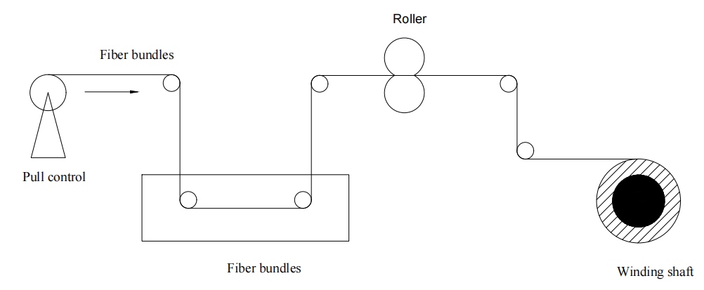
Dry winding molding uses prepreg yarns or prepreg tapes as raw materials, which have been pre-impregnated with resin. These materials are softened to a tacky state through heating on a winding machine and then wound onto the mandrel for shaping. Compared to dry winding, wet winding molding does not require pre-preparation of prepreg materials; instead, fiber bundles are directly impregnated with liquid resin in a resin bath and immediately wound. This eliminates intermediate steps such as prepreg drying and storage, significantly shortening the production cycle and enabling the formation of composite products with specific structures and properties by integrating the resin matrix and fiber reinforcement [7]. The process flow diagram of the wet winding technique is shown in Figure 2.
Song et al. [8] investigated a flywheel rotor with a composite rim structure formed by fiber winding on a metal hub. They developed a direct winding process of T800H carbon fiber composite rims onto a 7050 aluminum alloy hub, enabling the flywheel rotor to operate normally. Chen et al. [9] studied the effects of fiber winding tension on the deformation of composite flywheel rotors. Using various materials—including S6 glass fiber, T700SC and T800SC carbon fibers, E-8012 epoxy resin, and Al7075 aluminum alloy as the flywheel hub—they established a 1/8 model in ABAQUS to simulate the influence of Constant Tension Winding (CTW) and Variable Tension Winding (IPWVT) on rotor deformation and failure. The results indicated that deformation within the elastic range effectively characterizes the stress state of composite layers, and that variable tension winding reduces plastic deformation of the hub. When the relative thickness λ > 1.3, the influence of outer winding on the mandrel deformation diminishes, and curing relaxation is independent of tension. The magnitude of winding tension directly affects the structural strength and performance of the flywheel. Excessive tension may overstretch the fibers and degrade material properties, whereas insufficient tension leads to loose fiber bonding, increasing the risk of loosening at high rotational speeds and compromising the rotor’s integrity. To increase the maximum rotational speed achievable by rotors manufactured via winding processes, Hui et al. [10] employed an innovative high-tension winding technique to induce interference fit between the composite jacket and the hub. They analyzed the effects of winding tension and interference fit between the hub and shaft on compressive stresses at the interface of glass fiber and carbon fiber rotor materials under 30,000 RPM and varying operating temperatures. This method effectively increased the laminated composite stress by 30 to 60 N. Because traditional fiber-wound composite flywheels exhibit high circumferential strength but only about 1% of that in radial strength, they are highly susceptible to delamination caused by radial tensile stresses during high-speed rotation, limiting the increase of total stored energy. Although interference fits or tensioned winding processes can mitigate radial stresses, large-size flywheels are difficult to machine accurately, making it challenging to ensure manufacturing precision. Therefore, Tang et al. [11], based on the rule of mixtures to derive elastic constants, established mechanical equations for radial compressive stress in single-layer and multilayer flywheels and designed and fabricated a six-layer interleaved flywheel. This process achieves radial compressive stress to counteract centrifugal tensile stress, effectively preventing radial delamination. Meng [12] utilized a multi-ring interference-fit structure composed of an aluminum alloy hub and composite rim rings. By cooling the hub with liquid nitrogen and subsequently assembling the rings, thermal expansion generates a pre-compressive stress that offsets radial tensile stresses during high-speed rotation, thereby optimizing the fiber winding forming process and improving energy storage density. After optimization, the flywheel rotor achieved a total energy storage of 3.6 kWh and an energy density of 129 Wh/kg, representing a 49% increase over elastic design, with a maximum rotational speed of 42,038 rpm. Dai [13] developed a manufacturing process for a plain-woven laminated composite flywheel to address the delamination tendency of fiber winding processes. The woven structure consists of circumferential yarn bundles continuously woven as single fiber bundles, with radial yarn bundles arranged in a radial distribution to achieve radial reinforcement.
3.2. Interference fit assembly and press-fitting forming process
Interference fit assembly is currently a widely studied manufacturing process. To improve the overall strength and stiffness of the flywheel, thereby further increasing its energy storage density, the metal hub and composite rim can be assembled using an interference fit. Due to the tensile properties of composite materials, the interference fit generates a pre-tightening force at the contact interface between the two components, which enhances the overall mechanical performance of the flywheel. Tang et al. [14] designed a magnetically suspended outer rotor flywheel with a metal hub and three composite rings assembled via interference fit. Using a sequential quadratic programming method, the rotor was optimally designed, resulting in a 34.5% increase in both energy storage capacity and energy storage density. Since interference fit assembly relies on the pre-tightening force generated by the fit between components, the magnitude of the interference and the elastic moduli of the materials involved play decisive roles. Excessive interference can cause local stress concentrations in the composite parts, potentially leading to material cracking and significantly compromising the flywheel’s safety. Conversely, insufficient interference reduces the contact pressure and friction between the metal hub and composite rim; during high-speed operation, slight slip may occur at the contact interface, adversely affecting flywheel stability and reducing overall performance. Liang et al. [15] analyzed the interference fits of all mating components in a 10 kW·h magnetically suspended energy storage flywheel rotor under static and extreme rotational speeds. None of the components exceeded their material strength limits, and no separation occurred at the interference contact interfaces. Li et al. [16] developed design criteria and methods for the interference fit of multilayer jacketed motor rotors, ensuring sufficient contact pressure between rotor components under static and dynamic conditions and preventing delamination during high-speed rotation.
Tang et al. [17] established stress analysis models for rotors based on plane stress analytical methods and finite element methods, concluding that adding a metal hub, increasing the thickness of the composite outer ring, and enlarging the interference fit between the middle and outer rings can enhance the rotor’s strength, maximum rotational speed, and energy storage density.
4. Optimization design of composite material flywheel rotor structures
In composite flywheel rotors, to meet the stress demands of high-speed rotation, composite rims are assembled onto high-strength steel or titanium alloy hubs using interference fit methods. Due to the complex mechanical properties of composite materials, simple structural designs of composite flywheels significantly limit the full utilization of their material capabilities. This is especially true in systems where the flywheel is subjected to high-speed rotational centrifugal forces and complex stress fields. Single-layer laminate designs are prone to stress concentration and delamination failure. When the flywheel operates at a constant angular velocity, the mechanical equilibrium equation for the composite rim structure [13] is as follows:
In the equation, σr and σ0 denote the radial and circumferential stresses, respectively; ρ and ω represent the density and rotational speed, respectively.
In flywheel structures, the most significant factor affecting the radial and circumferential stresses in the composite rim is the interference fit magnitude between the rims. As the interference increases, the radial stress experienced by the composite rim, which is compressive stress, increases significantly, and the circumferential stress, typically tensile stress, also rises markedly. Additionally, an increase in the friction coefficient at the rim contact interface leads to localized stress concentration in the assembled rim, influencing the tendency for slip at the contact surface during rotation. Structural parameters such as the rim inner diameter, hub outer diameter, rim thickness, hub size and stiffness, and rim width also impact the stress levels in the rim.
Currently, the mainstream research direction focuses on simulation studies of multi-ring composite interference-fit structures. By varying parameters such as the layup sequence of composite flywheel materials, the number of material rings, and flywheel dimensions, simulation analyses are conducted to optimize the performance of the flywheel during operation. Initially, Kale et al. [18] developed a one-dimensional, plane-stress, axisymmetric flywheel model based on Krack’s description and designed a four-rotor flywheel composed of metal and composite rims with rim separation constraints. Comparative analysis revealed that multi-rim composite rotors with specific material sequences assembled by interference fit outperform single-rim composite flywheels and metal flywheels in terms of total and specific energy, while also offering advantages of lighter weight and higher operational speeds.
Currently, research on composite material structural design mainly focuses on simulation studies of flywheel rotor structures. Ren et al. [19] established a multilayer interference-fit composite material stress analysis model tailored to the structural characteristics of flywheels. They investigated the radial and circumferential stress distributions of carbon fiber T300, carbon fiber T800, and glass fiber rims operating at 15,000 rpm. Based on these stress characteristics, they concluded that an inner layer of low-cost glass fiber, a middle layer of carbon fiber T300, and an outer layer of higher-cost carbon fiber T800 produce the most uniform stress distribution with minimal gradient variation. However, this optimization method, which only varies the layup sequence, is relatively simple. To simplify the composite flywheel optimization problem while better considering material mechanical properties and improving energy storage density, Michael et al. [20]. proposed a zoning material selection principle of “low modulus-high strength material + high modulus-high strength material.” In constant stress regions, low-density, low-modulus but high-strength M46J/epoxy material is used, while in constant thickness regions, high-modulus T1000G/epoxy material is selected. This approach reduces stress non-uniformity caused by material self-weight and suppresses deformation of the composite during high-speed rotation, thereby increasing the maximum rotational speed. Liu et al. [21] selected T700/AG80 carbon fiber reinforced resin composites and employed a three-layer multi-ring fiber winding structure. They simplified the energy storage density optimization problem of the composite flywheel rotor into a nonlinear programming problem with multiple variables and a single objective. Using a particle swarm optimization algorithm, the optimized hub outer diameter was 170 mm; the interference fits between the hub and inner ring and between the inner and outer rings were both 0.3 mm; and the radial thicknesses of the inner and outer ring layers were 15 mm, resulting in a 22.8% improvement in energy storage density. Li et al. [22] used three-dimensional finite element methods to analyze the effect of the taper size at the contact surfaces of multilayer interference-fit composite rims and metal hubs on radial stress distribution in flywheel rotors. They found that the taper size has a minor effect on rim radial stress distribution and that changes in taper size correlate positively only with the magnitude of radial stress at axial edge locations of the rotor.
To accommodate varying performance requirements of composite flywheel energy storage rotors in different application scenarios and improve their robustness, Wen et al. [23] proposed a displacement-based optimization method for multi-ring flywheel structures. This method considers four performance indicators under different application conditions: energy per unit mass, energy per unit volume, energy per unit cost, and energy per unit mass cost, providing theoretical support for lightweight, low-cost, and high-reliability design of flywheel energy storage systems. In terms of applications, Pish [24] designed a robust composite flywheel for use in microgrids, achieving high energy density and long-term mechanical stability for microgrid systems.
5. Future development trends
5.1. Innovations in composite materials
The primary factor currently limiting the maximum rotational speed of flywheel energy storage systems remains the mechanical performance of composite materials. Traditional composite flywheels exhibit radial strength only about 1% of their circumferential strength. Moreover, due to the anisotropic nature of composite materials, stress distribution during rotation is non-uniform. When stresses generated during rotation exceed the maximum allowable stress of the composite, the rotor deforms under centrifugal forces, causing stress concentration in the hub–rim transition zone, and potentially leading to slip and delamination hazards. Therefore, continued exploration of novel composite materials is essential to improve reliability and stability under high-speed operation, reduce manufacturing costs, and further enhance the flywheel’s energy storage density and maximum rotational speed. The UT-CEM Laboratory in the United States developed a Carbon Nanotube (CNT)-doped epoxy resin by incorporating 0.5-1% CNTs, creating a CNT-modified resin capable of increasing interlaminar shear strength by 30-50% while reducing matrix creep rates. Rotational tests of the CNT-modified resin material demonstrated that after 1,000 hours of operation at 120,000 rpm, the interlaminar stress decay rate decreased from 25% to 8% in the CNT-reinforced system.
5.2. Manufacturing processes
Different manufacturing processes have their own advantages and disadvantages. For composite flywheels, the current mainstream manufacturing methods are winding curing and interference fit assembly. However, both face challenges such as difficulties in assembly precision and stress control, as well as relatively high process costs and long production cycles. In winding curing processes, controlling the winding tension is paramount. Insufficient winding tension may increase the risk of delamination in the flywheel rotor, whereas excessive tension can cause stresses that exceed the critical maximum stress of the composite material itself. Regarding interference fit assembly, accurately calculating the interference magnitude is crucial. If the interference is too small, the contact pressure and friction force between the metal hub and composite rim decrease, adversely affecting the flywheel’s stability. Conversely, excessive interference can induce localized high stresses in the composite rim, compromising the flywheel’s safety. Therefore, when designing interference fit assemblies, various factors influencing the interference magnitude must be considered. For example, the high temperatures generated during high-speed rotation can cause material expansion, affecting the interference at the rim contact interface. Consequently, exploring novel manufacturing techniques for flywheel rotors is a direct means to enhance structural safety and stability. An ideal manufacturing process should be simple, require minimal manufacturing equipment, maximize material utilization and process flexibility, and produce flywheels with high stability and low risk of failure.
5.3. Flywheel rotor structures
Currently, most domestic research on composite flywheel rotor structures focuses on static and dynamic simulations using software such as ANSYS and Abaqus, primarily employing finite element analysis to predict stress distributions under high-speed rotation. This simulation-heavy, practice-light approach is mainly due to the high experimental costs, manufacturing process barriers for flywheel rotors, and inherent safety risks. Consequently, most studies remain at the simulation stage. An effective flywheel structure should be capable of accommodating various real-world factors that reduce energy storage density. Additionally, it should implement a highly adaptable evaluation system tailored to different application conditions. Such a system would guide targeted rotor design and enable the analysis of discrepancies between simulated and actual operational conditions. By complementing mature simulations with practical experimentation, the structural design of flywheel rotors can be advanced toward large-scale applications in fields such as microgrids and rail transit.
6. Conclusion
As a core approach to efficient physical energy storage, flywheel energy storage technology critically depends on the stress analysis of rotor materials and structures to ensure high system reliability and energy density. This paper systematically reviews the research progress on the mechanical properties of flywheel rotor materials, manufacturing processes, and structural optimization, revealing the following key conclusions.
6.1. Breakthroughs and challenges in material performance
Composite materials, exemplified by T1000 carbon fiber achieving an energy storage density of 945.7 Wh/kg, significantly outperform traditional metals due to their high specific strength. However, anisotropy-induced radial stress concentration—where radial strength is only about 1% of circumferential strength—remains a bottleneck for increasing rotational speed. Novel materials such as Carbon Nanotube (CNT)-modified resins, which enhance interlaminar shear strength by 30–50% and suppress creep, offer new avenues for breaking speed limits, demonstrated by stable operation at 120,000 rpm over extended durations.
6.2. Refined control of manufacturing processes
In winding curing processes, tension control (e.g., variable tension winding IPWVT) and the design of interference fit magnitude in assembly directly govern rotor stress distribution. The wet winding process, favored for its efficiency, requires balancing winding tension and resin impregnation quality. Interference fit assembly depends on precise calculation of interference magnitude—excessive interference risks cracking, whereas insufficient interference may cause slippage. Optimization must integrate multiphysics coupling models.
6.3. Collaborative innovation in structural design
Multi-ring hybrid structures (e.g., layered glass fiber/carbon fiber designs) and topology optimization effectively balance stress distribution, leading to energy density improvements between 22.8% and 49% (e.g., optimized flywheels by Meng achieving 129 Wh/kg). Future work should deepen synergy across “materials-structure-process”: developing high-temperature-resistant, low-creep matrix materials; exploring additive manufacturing and other low-stress forming technologies; and employing deep learning for full life-cycle stress prediction.
6.4. Urgency of industry-academia-research integration
Current research remains simulation-centric (e.g., ABAQUS, ANSYS), with experimental validation limited by cost and safety risks. Future efforts should establish a closed loop of “simulation-pilot testing-engineering,” promoting large-scale deployment of flywheel energy storage in microgrids and rail transit applications, thereby supporting the construction of new power systems under the dual carbon goals.
References
[1]. Xue, F. Y., & Liang, S. Y. (2020). Development status and prospects of core technology for flywheel energy storage.Energy Conservation, 39(11), 119–122.
[2]. Pi, Z. H., Dai, X. J., Wei, D. J., & Xu, Y. (2019). Capacity analysis and design of flywheel energy storage system.Energy Storage Science and Technology, 8(4), 778–783.
[3]. Ma, X. Y., & Li, W. Y. (2024). Comparison of energy storage characteristics and finite element analysis of flywheel rotors made of different materials.Mechanical Design, 41(7), 21–27.
[4]. Song, J. P., Wang, J. W., Luo, H., Fan, X. B., & Gui, L. (2021). Tensile mechanical properties study of carbon fiber composite ring.Composite Materials Science and Engineering, (6), 65–71.
[5]. Zong, Y., Yin, Y., Xie, S. Y., & Yang, G. (2024). Structural simulation analysis of composite flywheel rotor.Ship Electrical Technology, 44(4), 61–64.
[6]. Zhang, Y. Z., & Li, L. (2023). Finite element analysis of strength and modal characteristics of flywheel energy storage rotor.Journal of Hunan Institute of Engineering (Natural Science Edition), 33(3), 16–21.
[7]. Li, Z., Jiang, T., Pei, Y. M., He, S. J., & Kong, D. Q. (2013). Research progress on composite flywheel energy storage rotor.Materials Review, 27(3), 64–69, 73.
[8]. Song, Y. G., Li, C., & Li, W. Y. (2013). Finite element simulation of composite flywheel rotor molding process.Mechanical Science and Technology, 32(10), 1456–1460.
[9]. Chen, X., Li, Y., Huan, D., Liu, H., Li, L., & Li, Y. (2022). Influence of filament winding tension on the deformation of composite flywheel rotors with H-shaped hubs.Polymers, 14(6), 1155.
[10]. Hui, P., Zu, L., Li, S. X., Wang, Y., & Zhou, F. (2018). Research on high-tension winding carbon fiber composite high-speed flywheel rotor.Composite Materials Science and Engineering, 2018(3), 5–12.
[11]. Tang, C. L., Dai, X. J., & Wang, Y. (2015). Mechanical design and rotation test of multilayer hybrid composite flywheel.Journal of Tsinghua University (Science and Technology), 55(3), 361–367.
[12]. Meng, Z. H. (2004). Structural and material optimization of composite flywheel rotors for electric vehicles [Master's thesis, Wuhan University of Technology].
[13]. Dai, X. J., Wei, K. P., & Wang, Y. (2019). Elastic parameter prediction and measurement of plain weave laminated composite flywheel.Journal of Composite Materials, 36(12), 2833–2842.
[14]. Tang, J. Q., Zhang, Y. B., & Zhao, L. B. (2013). Interference fit metal hub-composite flywheel rotor.Optics and Precision Engineering, 21(10), 2639–2647.
[15]. Liang, Z. H., Huang, Y. S., Zhang, F., Cai, X. K., Han, M., & Su, S. (2024). Rotor design of 10 kW·h magnetic suspension energy storage flywheel.Mechanical Design, 41(11), 152–160.
[16]. Li, S. T., Zhang, X. Q., Wang, C. C., Li, X., Su, S., & Peng, L. (2024). Interference fit analysis and assembly process of multi-layer jacketed motor rotor.Micro Motors, 57(11), 68–74.
[17]. Tang, J.-Q., Zhang, Y.-B., & Zhao, L.-B. (2013). Interference fit of metal hub-composite flywheel rotors.Optics and Precision Engineering, 21(10), 2639–2647.
[18]. Kale, V., & Secanell, M. (2018). A comparative study between optimal metal and composite rotors for flywheel energy storage systems.Energy Reports, 4, 576–585.
[19]. Ren, Z. Y., Zhang, S. W., Yang, L. P., & Huang, T. (2019). Study on stress influence law of material stacking sequence on energy storage flywheel.Composite Materials Science and Engineering, (1), 23–27.
[20]. Conteh, M. A., & Nsofor, E. C. (2016). Composite flywheel material design for high-speed energy storage.Journal of Applied Research and Technology, 14(3), 184–190.
[21]. Liu, C., Cai, X. J., An, Q. L., & Chen, M. (2022). Structural design optimization of composite flywheel rotor energy storage.Mechanical Design and Manufacturing, 380(10), 278–280, 284.
[22]. Li, W. T., Wang, G. N., Wang, T., Li, R. X., Wu, Q. B., Chen, Z. G., ... & Zhang, L. W. (2023). Finite element analysis of cylindrical composite flywheel rim.Mechanical Engineer, (10), 100–103, 106.
[23]. Wen, S., & Jiang, S. (2012). Optimum design of hybrid composite multi-ring flywheel rotor based on displacement method.Composites Science and Technology, 72(9), 982–988.
[24]. Pish, S., Pe, S. M., Hahne, J., Beno, J., & Hebner, R. (2023, August). Design and manufacture of robust composite flywheels for microgrids. In 2023 IEEE Electric Ship Technologies Symposium (ESTS) (pp. 66–71). IEEE.
Cite this article
Deng,B. (2025). A review of stress analysis on materials and structures for flywheel energy storage systems. Advances in Engineering Innovation,16(8),84-91.
Data availability
The datasets used and/or analyzed during the current study will be available from the authors upon reasonable request.
Disclaimer/Publisher's Note
The statements, opinions and data contained in all publications are solely those of the individual author(s) and contributor(s) and not of EWA Publishing and/or the editor(s). EWA Publishing and/or the editor(s) disclaim responsibility for any injury to people or property resulting from any ideas, methods, instructions or products referred to in the content.
About volume
Journal:Advances in Engineering Innovation
© 2024 by the author(s). Licensee EWA Publishing, Oxford, UK. This article is an open access article distributed under the terms and
conditions of the Creative Commons Attribution (CC BY) license. Authors who
publish this series agree to the following terms:
1. Authors retain copyright and grant the series right of first publication with the work simultaneously licensed under a Creative Commons
Attribution License that allows others to share the work with an acknowledgment of the work's authorship and initial publication in this
series.
2. Authors are able to enter into separate, additional contractual arrangements for the non-exclusive distribution of the series's published
version of the work (e.g., post it to an institutional repository or publish it in a book), with an acknowledgment of its initial
publication in this series.
3. Authors are permitted and encouraged to post their work online (e.g., in institutional repositories or on their website) prior to and
during the submission process, as it can lead to productive exchanges, as well as earlier and greater citation of published work (See
Open access policy for details).
References
[1]. Xue, F. Y., & Liang, S. Y. (2020). Development status and prospects of core technology for flywheel energy storage.Energy Conservation, 39(11), 119–122.
[2]. Pi, Z. H., Dai, X. J., Wei, D. J., & Xu, Y. (2019). Capacity analysis and design of flywheel energy storage system.Energy Storage Science and Technology, 8(4), 778–783.
[3]. Ma, X. Y., & Li, W. Y. (2024). Comparison of energy storage characteristics and finite element analysis of flywheel rotors made of different materials.Mechanical Design, 41(7), 21–27.
[4]. Song, J. P., Wang, J. W., Luo, H., Fan, X. B., & Gui, L. (2021). Tensile mechanical properties study of carbon fiber composite ring.Composite Materials Science and Engineering, (6), 65–71.
[5]. Zong, Y., Yin, Y., Xie, S. Y., & Yang, G. (2024). Structural simulation analysis of composite flywheel rotor.Ship Electrical Technology, 44(4), 61–64.
[6]. Zhang, Y. Z., & Li, L. (2023). Finite element analysis of strength and modal characteristics of flywheel energy storage rotor.Journal of Hunan Institute of Engineering (Natural Science Edition), 33(3), 16–21.
[7]. Li, Z., Jiang, T., Pei, Y. M., He, S. J., & Kong, D. Q. (2013). Research progress on composite flywheel energy storage rotor.Materials Review, 27(3), 64–69, 73.
[8]. Song, Y. G., Li, C., & Li, W. Y. (2013). Finite element simulation of composite flywheel rotor molding process.Mechanical Science and Technology, 32(10), 1456–1460.
[9]. Chen, X., Li, Y., Huan, D., Liu, H., Li, L., & Li, Y. (2022). Influence of filament winding tension on the deformation of composite flywheel rotors with H-shaped hubs.Polymers, 14(6), 1155.
[10]. Hui, P., Zu, L., Li, S. X., Wang, Y., & Zhou, F. (2018). Research on high-tension winding carbon fiber composite high-speed flywheel rotor.Composite Materials Science and Engineering, 2018(3), 5–12.
[11]. Tang, C. L., Dai, X. J., & Wang, Y. (2015). Mechanical design and rotation test of multilayer hybrid composite flywheel.Journal of Tsinghua University (Science and Technology), 55(3), 361–367.
[12]. Meng, Z. H. (2004). Structural and material optimization of composite flywheel rotors for electric vehicles [Master's thesis, Wuhan University of Technology].
[13]. Dai, X. J., Wei, K. P., & Wang, Y. (2019). Elastic parameter prediction and measurement of plain weave laminated composite flywheel.Journal of Composite Materials, 36(12), 2833–2842.
[14]. Tang, J. Q., Zhang, Y. B., & Zhao, L. B. (2013). Interference fit metal hub-composite flywheel rotor.Optics and Precision Engineering, 21(10), 2639–2647.
[15]. Liang, Z. H., Huang, Y. S., Zhang, F., Cai, X. K., Han, M., & Su, S. (2024). Rotor design of 10 kW·h magnetic suspension energy storage flywheel.Mechanical Design, 41(11), 152–160.
[16]. Li, S. T., Zhang, X. Q., Wang, C. C., Li, X., Su, S., & Peng, L. (2024). Interference fit analysis and assembly process of multi-layer jacketed motor rotor.Micro Motors, 57(11), 68–74.
[17]. Tang, J.-Q., Zhang, Y.-B., & Zhao, L.-B. (2013). Interference fit of metal hub-composite flywheel rotors.Optics and Precision Engineering, 21(10), 2639–2647.
[18]. Kale, V., & Secanell, M. (2018). A comparative study between optimal metal and composite rotors for flywheel energy storage systems.Energy Reports, 4, 576–585.
[19]. Ren, Z. Y., Zhang, S. W., Yang, L. P., & Huang, T. (2019). Study on stress influence law of material stacking sequence on energy storage flywheel.Composite Materials Science and Engineering, (1), 23–27.
[20]. Conteh, M. A., & Nsofor, E. C. (2016). Composite flywheel material design for high-speed energy storage.Journal of Applied Research and Technology, 14(3), 184–190.
[21]. Liu, C., Cai, X. J., An, Q. L., & Chen, M. (2022). Structural design optimization of composite flywheel rotor energy storage.Mechanical Design and Manufacturing, 380(10), 278–280, 284.
[22]. Li, W. T., Wang, G. N., Wang, T., Li, R. X., Wu, Q. B., Chen, Z. G., ... & Zhang, L. W. (2023). Finite element analysis of cylindrical composite flywheel rim.Mechanical Engineer, (10), 100–103, 106.
[23]. Wen, S., & Jiang, S. (2012). Optimum design of hybrid composite multi-ring flywheel rotor based on displacement method.Composites Science and Technology, 72(9), 982–988.
[24]. Pish, S., Pe, S. M., Hahne, J., Beno, J., & Hebner, R. (2023, August). Design and manufacture of robust composite flywheels for microgrids. In 2023 IEEE Electric Ship Technologies Symposium (ESTS) (pp. 66–71). IEEE.