


1. Introduction
The textile industry is one of the pillar industries in China, and improving the technological level of textile machinery contributes to the high-quality development of the entire textile sector. As one of the key devices in spinning, the cotton-feeding mechanism plays the role of delivering raw cotton fibers to subsequent processes. The stability of its operation and the uniformity of cotton feeding directly determine both yarn quality and production line efficiency. With the rapid development of textile production, higher requirements have been placed on the speed and precision of textile machinery. Since traditional cotton-feeding mechanisms cannot fully meet the needs of the textile industry, it is necessary to conduct in-depth studies of their internal mechanisms from the perspective of mechanical principles in order to optimize performance. Kinematic analysis is one of the most fundamental methods in mechanical engineering for studying the motion of mechanisms. By examining motion laws without considering external forces, it can identify design deficiencies and guide improvements in mechanism design and motion performance. Although kinematic analysis has been widely applied in mechanical equipment such as internal combustion engines and industrial robots to achieve optimization, its application to cotton-feeding mechanisms in textile machinery remains relatively limited. Existing studies in this area are mostly focused on material properties and control systems, without giving sufficient attention to how optimizing the kinematics of the mechanism can affect its motion performance.
2. Literature review
In the field of linkage mechanism research, different types of linkages have been widely applied in various engineering scenarios due to their distinctive motion characteristics, and related studies are both abundant and continually deepening. The crank-rocker mechanism, composed of a crank, connecting rod, rocker, and frame, enables the crank to perform full-rotation motion while the rocker executes reciprocating oscillation. In the case of automotive windshield wipers, a dynamic analysis of the wiper system shows that the motor drives the crank to rotate [1], which in turn drives the wiper arm to swing via the connecting rod, ensuring smooth and continuous wiping on the windshield and effectively safeguarding the driver’s field of vision. In radar antenna elevation mechanisms, based on actual radar engineering requirements, it is explained how the crank-rocker mechanism transmits crank rotation to rocker oscillation, thereby achieving precise adjustment of the antenna’s elevation angle to meet the needs of detecting targets in different airspaces [2]. In a double-crank mechanism, both links act as cranks capable of synchronized full-rotation motion. In aircraft cabin door actuation mechanisms, the use of a double-crank system converts the input of a rotary actuator into precise, synchronized motion at two or more output points, enabling large cabin doors to open and close with accurate trajectories free from interference [3]. In bionic legged robots, the double-crank mechanism is employed as a hip or knee joint. By adopting a parallelogram mechanism, the thigh can swing while keeping the body height unchanged, resulting in a more stable walking gait. In bionic fish propulsion systems, a double-crank mechanism has been studied to drive robotic fish tails. A single motor drives a set of double cranks, converting rotational motion into symmetrical side-to-side oscillation of the tail fin, simulating fish swimming and providing more efficient and stable thrust compared to the simpler crank-rocker mechanism. In a double-rocker mechanism, both links can only perform reciprocating oscillation. In aircraft landing gear retraction systems, the mechanism is designed so that when the landing gear is fully deployed, the connecting rod and rocker approach a collinear position [4]. By exploiting the self-locking property at this position, the system can withstand large impact loads without requiring the actuator to provide continuous high locking force, thereby greatly enhancing reliability. In aircraft aileron or multi-surface linkage systems, a single actuator can drive multiple control surfaces simultaneously [5]. Here, a double-rocker mechanism acts as a motion distributor, converting the oscillation of one input rocker into specific proportional oscillations of two or more output rockers, thereby enabling complex flight control logic. The crank-slider mechanism, consisting of a crank, connecting rod, and slider, also has diverse applications. In mechanical presses and stamping machines, replacing the traditional flywheel with a servo motor allows programmed control of the slider’s motion profile, enabling customized processes such as stamping, holding, and return, thereby significantly improving forming quality. In internal combustion engines, the high-speed reciprocating motion of pistons generates substantial inertial forces, which are the main source of vibration and noise. For a high-performance diesel engine, a multibody dynamic model of the crank-slider system was established to analyze the effect of second-order inertial forces on engine vibration [6]. By optimizing the balance shaft configuration, vibration amplitude was successfully reduced by 15%. Such research is critical for enhancing engine smoothness and Noise, Vibration, and Harshness (NVH) performance. In summary, different types of linkage mechanisms, by virtue of their motion characteristics, meet diverse engineering demands across their application domains. These studies provide a solid foundation for further optimization and innovation. However, there remains room for expansion in areas such as the study of complex systems involving multi-linkage coordination and the development of mechanisms adapted to higher-speed, higher-precision, and intelligent requirements.
3. Calculation of kinematic parameters and simulation analysis for the key sub-mechanisms of the cotton-feeding machine
As show in Figure 1, the intermittent take-up-roller driven clamp-type cotton-feeding machine was selected as the core research object. This device is the key cotton-conveying component in textile production, responsible for reliably delivering raw cotton fibers to subsequent spinning processes. The motion precision of its drive mechanisms (the slotted-wheel mechanism, the ratchet anti-reverse device, and the take-up roller assembly) directly affects the uniformity of cotton feed and the continuity of production, making it a representative and practically valuable case for kinematic analysis. Composition of the take-up roller drive mechanism: slotted-wheel mechanism; ratchet anti-reverse device; take-up roller assembly. Based on the structural composition of the drive mechanism and combined with the basic principles of planar-mechanism kinematics, a mathematical model was constructed. The first step was to decompose the three sub-mechanisms—the slotted-wheel mechanism, the ratchet anti-reverse device, and the take-up roller assembly—and to identify for each sub-mechanism the number of moving members, the types of kinematic pairs, and the connection relationships among components. The second step was to substitute the results into the planar-mechanism degree-of-freedom formula to compute the overall degree of freedom and verify whether the mechanism has determinate motion (i.e., degree of freedom = 1, matching the single input of the textile machine drive system), thereby laying the foundation for subsequent motion analysis.
Degree-of-freedom calculation is shown in Figure 1.
![Figure 1. Rolling roller mechanism [7]](https://file.ewadirect.com/press/media/markdown/document-image1_Pg7pfp8.png)
Planar mechanism degree-of-freedom formula:
Mechanism decomposition and parameter statistics: By disassembling the cotton-feeding machine drive mechanism, the core parameters of each sub-mechanism were tallied. In the slotted-wheel mechanism, the moving members are the drive pin wheel and the slotted wheel (2 total); lower pairs include the pin-wheel–frame revolute pair and the slotted-wheel–frame revolute pair (2 total); the higher pair is the meshing contact between the drive pin and the slotted wheel (1). In the ratchet anti-reverse device, the moving members are the ratchet wheel and the pawl (2 total); lower pairs include the ratchet-wheel–frame revolute pair and the pawl–frame revolute pair (2 total); the higher pair is the meshing contact between pawl and ratchet (1). In the take-up roller assembly, the moving members are the driving roller and the driven roller (2 total); lower pairs include the driving-roller–frame revolute pair and the driven-roller–spring translation/rev pair (2 total); there are no higher pairs. According to the statistics, the total number of moving members is n = 2 + 2 + 2 = 6, the total number of lower pairs is Pl = 2 + 2 + 2 = 6, and the total number of higher pairs is Ph = 1 + 1 = 2. Substituting these values into the planar mechanism degree-of-freedom formula yields:F = 3n − 2Pl − Ph. The calculation yields F = 3 × (6 − 1) − 2 × 6 − 2 = 15 − 12 = 1.
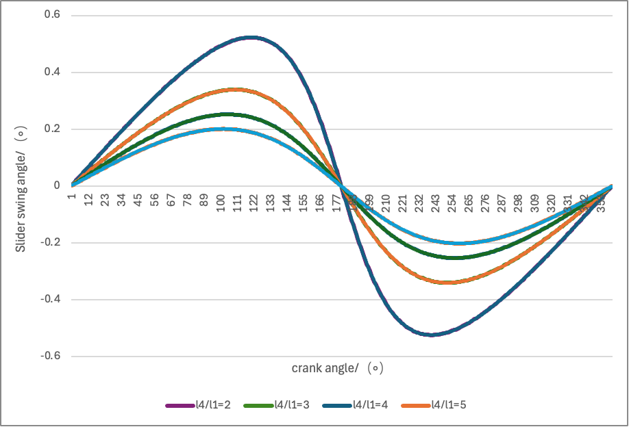
In addition to the basic planar-mechanism degree-of-freedom formula, and for the purpose of analyzing the motion characteristics of the cotton-feeding machine’s key subassemblies, we supplement the following core relations: Angular displacement of the clamp-plate pivot
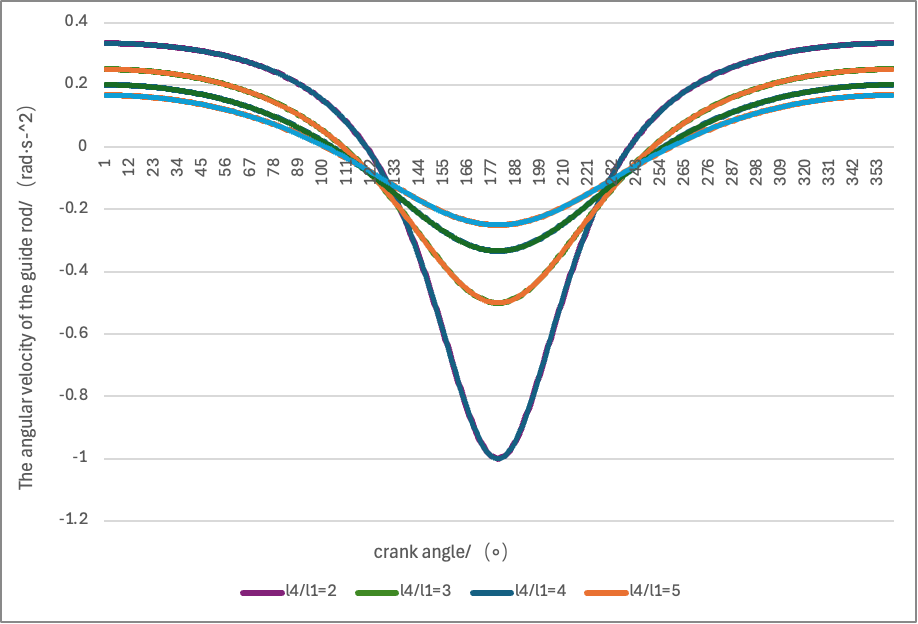
Angular velocity of the clamp-plate pivot:
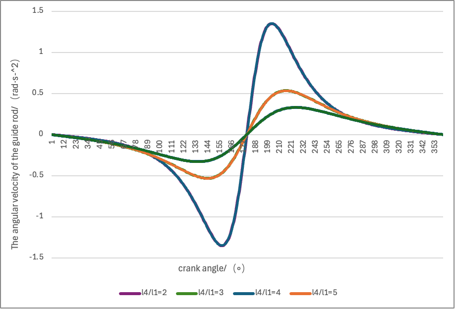
Angular acceleration of the clamp-plate pivot:
As show in Figure 2, Figure 3 and Figure 4: We also selected several different values of the link-length ratio l4/l1 to better characterize its influence, and drew the following three plots for visual inspection:
4. Conclusions
On this basis, analysis and experiments revealed two major technical difficulties in the present study. The first major difficulty is that the initial Degree-of-Freedom (DoF) estimates have a large error rate. Taking the intermittent take-up-roller–driven clamp-type cotton-feeding machine as an example, some kinematic pairs overlap or intersect, which can produce redundant constraints. For instance, if the pawl-to-frame revolute pair is mistakenly identified as a prismatic (sliding) pair when counting the lower pairs of the ratchet anti-reverse device, the total count of lower pairs will be wrong and the calculated DoF may be 2, whereas the correct value should be 1. When dealing with the driven-roller pressure-adjustment spring group, it is also difficult to determine which constraints are redundant, because in modeling it is hard to tell whether the constraint introduced by a spring is redundant; this ambiguity affects the accuracy of the DoF calculation. The second major difficulty lies in building combined-motion models for link-and-cam assemblies. In this study, the slotted-wheel and ratchet mechanisms both perform periodic intermittent motions, and the rotation of the take-up roller and the translation of the driven roller are mutually coupled. These interactions require consideration of the motion parameters of different sub-mechanisms; therefore the conventional approach of writing motion equations for each single mechanism and simply summing them cannot reflect the actual cooperative behavior and fails to produce an accurate system model. To resolve the DoF calculation issues, the complex mechanism was first decomposed into three modules—slotted wheel, ratchet, and rollers—and the moving members and kinematic pairs within each module were clearly marked. Then, following the textbook method for identifying redundant constraints in mechanical-principles literature, the spring constraints were analyzed; this procedure revealed the source of the counting error. To overcome the modeling difficulty, relevant chapters on DoF calculation from texts such as Mechanics of Machines and Fundamentals of Textile Machine Design were consulted, and examples from academic databases were reviewed to trace errors in the calculation process. Concurrently, different model formulations and iterative tests were used to continually revise and improve the models, ultimately producing a combined-motion model that approximates actual working conditions and exhibits improved simulation stability. The research findings show that the DoF of the intermittent take-up-roller clamp-type cotton-feeding machine drive system is 1—that is, it equals the number of input members—and the motion is determinate. As the link-length ratio
References
[1]. Yu, Z. (2015). Dynamic analysis of wiper system and prediction of return impact noise [Doctoral dissertation, Beijing Institute of Technology].
[2]. Niu, Y. S. (2001). Analysis and calculation of pitch mechanism of a vehicle-mounted radar antenna.Electronic Mechanical Engineering, (2), 4-7.
[3]. Guadaño, L. H., Valdés, R. M. A., & Nieto, F. J. S. (2014). Using aircraft as wind sensors for estimating accurate wind fields for air traffic management applications.Proceedings of the Institution of Mechanical Engineers, Part G: Journal of Aerospace Engineering, 228(14), 2681–2694. https: //doi.org/10.1177/0954410014524741
[4]. Burner, A. W., Liu, T., Garg, S., Bell, J. H., & Morgan, D. G. (1999). Unified model deformation and flow transition measurements.Journal of Aircraft, 36(5), 761-769.
[5]. Zhu, L. Y. (2007). A C-17 flight control system.Aircraft Design, (4), 1-6.
[6]. Leermakers, C. A. J., Berge, B. V. D., Luijten, C. C. M., Somers, L. M. T., & Albrecht, B. A. (2011). Gasoline-diesel dual fuel: Effect of injection timing and fuel balance.SAE Technical Paper, (1), 24-43.
[7]. Chen, G., & Sun, Z. H. (2020). Fundamentals of textile machinery design. China Textile Press Co., Ltd.
Cite this article
Han,Z. (2025). Research on performance optimization of intermittent cotton feeding machine based on kinematic analysis of mechanism. Advances in Engineering Innovation,16(9),69-74.
Data availability
The datasets used and/or analyzed during the current study will be available from the authors upon reasonable request.
Disclaimer/Publisher's Note
The statements, opinions and data contained in all publications are solely those of the individual author(s) and contributor(s) and not of EWA Publishing and/or the editor(s). EWA Publishing and/or the editor(s) disclaim responsibility for any injury to people or property resulting from any ideas, methods, instructions or products referred to in the content.
About volume
Journal:Advances in Engineering Innovation
© 2024 by the author(s). Licensee EWA Publishing, Oxford, UK. This article is an open access article distributed under the terms and
conditions of the Creative Commons Attribution (CC BY) license. Authors who
publish this series agree to the following terms:
1. Authors retain copyright and grant the series right of first publication with the work simultaneously licensed under a Creative Commons
Attribution License that allows others to share the work with an acknowledgment of the work's authorship and initial publication in this
series.
2. Authors are able to enter into separate, additional contractual arrangements for the non-exclusive distribution of the series's published
version of the work (e.g., post it to an institutional repository or publish it in a book), with an acknowledgment of its initial
publication in this series.
3. Authors are permitted and encouraged to post their work online (e.g., in institutional repositories or on their website) prior to and
during the submission process, as it can lead to productive exchanges, as well as earlier and greater citation of published work (See
Open access policy for details).
References
[1]. Yu, Z. (2015). Dynamic analysis of wiper system and prediction of return impact noise [Doctoral dissertation, Beijing Institute of Technology].
[2]. Niu, Y. S. (2001). Analysis and calculation of pitch mechanism of a vehicle-mounted radar antenna.Electronic Mechanical Engineering, (2), 4-7.
[3]. Guadaño, L. H., Valdés, R. M. A., & Nieto, F. J. S. (2014). Using aircraft as wind sensors for estimating accurate wind fields for air traffic management applications.Proceedings of the Institution of Mechanical Engineers, Part G: Journal of Aerospace Engineering, 228(14), 2681–2694. https: //doi.org/10.1177/0954410014524741
[4]. Burner, A. W., Liu, T., Garg, S., Bell, J. H., & Morgan, D. G. (1999). Unified model deformation and flow transition measurements.Journal of Aircraft, 36(5), 761-769.
[5]. Zhu, L. Y. (2007). A C-17 flight control system.Aircraft Design, (4), 1-6.
[6]. Leermakers, C. A. J., Berge, B. V. D., Luijten, C. C. M., Somers, L. M. T., & Albrecht, B. A. (2011). Gasoline-diesel dual fuel: Effect of injection timing and fuel balance.SAE Technical Paper, (1), 24-43.
[7]. Chen, G., & Sun, Z. H. (2020). Fundamentals of textile machinery design. China Textile Press Co., Ltd.