


1. Introduction
Power Electronic Transformers (PETs) are devices implemented through power electronic technologies and high-frequency transformers. Compared with traditional transformers, PETs offer multiple functions, including voltage transformation, electrical isolation, power regulation and control, and integration of renewable energy sources [1]. They also feature high controllability and the capability to regulate waveforms, power flows, and power quality, as well as to implement automatic protection control [2].
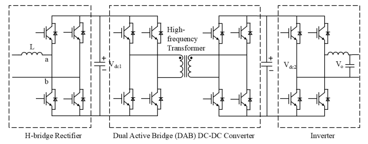
In recent years, PET technology has developed rapidly, with various topologies emerging successively. Figure 1 illustrates the three-level PET structure, which has attracted the greatest research attention among the various topologies. This topology can be divided into three parts: an H-bridge rectifier, a dual-active-bridge (DAB) DC–DC converter, and an inverter.
The various stages of a multi-level PET exhibit good independence, avoiding a direct AC/AC conversion stage and enhancing control flexibility [4,5]. This characteristic provides significant potential for applications involving the integration of diverse types of power sources, loads, and energy storage devices. Therefore, as PET topologies have gradually matured, research by domestic and international scholars has shifted toward optimizing control strategies for three-stage PETs [4].
This paper reviews and summarizes the key technical studies on control strategies for three-stage PETs, dividing the discussion into three parts: Section 1 introduces modulation techniques, including the control strategies for the input stage and the intermediate DAB stage; Section 2 presents voltage balancing and power balancing techniques; Section 3 covers port control technologies under multi-load integration scenarios; Section 4 summarizes the current development status of cascade PETs and outlines potential directions for optimizing their control strategies.
2. Modulation techniques for cascade power electronic transformers
Typically, cascade PETs are organized into three functional parts: an input stage, a middle conversion stage, and an output stage. The input stage, as the first stage of the PET, is primarily responsible for converting the AC grid input into the form of electrical energy required by the intermediate stage. At the input stage, frequently employed topologies are the Multilevel Cascaded H-Bridge (MLCHB) rectifier and the Modular Multilevel Converter (MMC). For the intermediate stage, the Dual Active Bridge (DAB) serves as a high-frequency isolated DC–DC converter, extensively adopted in PETs, EV chargers, renewable generation units, and energy storage applications. Its advantages include elevated efficiency, compact power density, and the ability to transfer energy bidirectionally.
Among input-stage topologies, the MLCHB has attracted research interest due to its excellent current harmonic performance, high-voltage capability, and highly modular structure. Compared with the basic CHB structure, the MLCHB increases the number of H-bridge units to achieve more output voltage levels, thereby expanding its application scenarios. MLCHBs are commonly used in high-voltage direct current (HVDC) transmission, high-power motor drives, and power quality improvement devices, offering advantages such as ease of implementation, high reliability, low harmonic distortion, and minimal waveform distortion [6]. MMC features a modular design in which each submodule can be independently controlled. Similar to MLCHB, MMCs are often applied in high-voltage scenarios and, as voltage-source converters for flexible DC transmission engineering, have attracted significant attention [7].
2.1. Input stage
For the input stage, the most common modulation methods are Phase-Shifted Carrier Pulse Width Modulation (PSC-PWM) and Space Vector Pulse Width Modulation (SVPWM). Both PSC-PWM and SVPWM can achieve effective control for MLCHB and MMC rectifiers. The following discussion focuses on these two input-stage modulation methods, providing a detailed review of control strategies under different topologies.
2.1.1. Phase-Shifted Carrier Pulse Width Modulation (PSC-PWM)
Phase-Shifted Carrier Pulse Width Modulation (PSC-PWM) is based on the carrier phase-shift method, in which multiple triangular carriers of identical amplitude but with phase shifts are compared with the modulation waveform to generate PWM signals that control each power unit separately, which are then superimposed to form a multilevel PWM waveform [8]. By using carrier phase-shift modulation, the phase of high-frequency current harmonics at the converter output can be altered, achieving a significant reduction in output-stage current harmonics [9,10]. Meanwhile, carrier phase-shift modulation allows submodules in a modular structure to synthesize a higher effective switching frequency at the AC side while operating at the same low switching frequency, thereby improving output waveform quality.
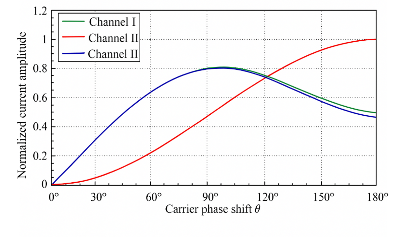
Reference [11] investigates a three-level H-bridge inverter, experimentally addressing the issue of abnormal neutral-line current increase when using PSC-PWM. A fifteen-phase three-level H-bridge inverter employs voltage pulse sequences to replace the reference voltage. Due to voltage asymmetry in the inverter bridge arms, alternating high-frequency common-mode voltages are generated between the stator windings of the load motor. Simultaneously, various distributed and parasitic capacitances in the motor system form closed common-mode loops. High-frequency common-mode voltage induces periodic charge motion across the parasitic capacitances through the common-mode loops, forming common-mode currents [11]. By calculating the circulating current amplitude, curves of three channels with respect to the carrier phase-shift angle θ were obtained (Fig. 2), showing that the neutral-line current increases sharply after applying the carrier phase shift.
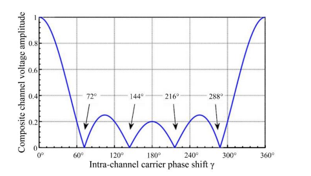
Analysis indicates that the root cause of the issue lies in the potential difference between the neutral points of each channel relative to ground. Circulating current amplitude can be suppressed by reducing the common-mode voltage amplitude. By calculating the expression for the neutral-point potential, the variation of neutral-point potential amplitude with the carrier phase-shift angle was obtained (Fig. 3). It was found that the amplitude reaches its minimum at a carrier phase-shift angle of 72°, thereby achieving suppression of the neutral-line current [11].
The Modular Multilevel Converter (MMC) is another common topology. Two main issues in the voltage balancing of submodule (SM) capacitors in MMCs are the reduction of switching frequency and the elimination of circulating currents. Reference [12] introduces an improved PSC-PWM scheme for MMCs, based on a Reduced Switching Frequency (RSF) voltage balancing algorithm.
In multilevel converters, PSC-PWM inherently mitigates lower-order harmonics. Yet, in its traditional form, each triangular carrier governs one submodule (SM), and inconsistencies in SM parameters often lead to imbalance in capacitor voltages. To address this issue, the Reduced Switching Frequency (RSF) scheme has been integrated into PSC-PWM, thereby enhancing voltage regulation. The overall modulation and balancing process is illustrated in Fig. 4, where two distinct frequencies are involved: fcr for the carrier frequency and fs for the sampling and control frequency.
The improved PSC-PWM method is illustrated in Fig. 5. According to the number of SMs N in each arm, the reference arm voltage is compared with NNN triangular carriers, each with a phase difference of 360°/N. Non represents the number of SMs that need to be switched on in each arm and serves as the output of the modulator.
SMs are selected based on the RSF algorithm. Switching pulses are generated by monitoring the SM capacitor voltages Uci ( i=1,2,…,N) and the arm currents icj or inj (j=1,2,…,N). To avoid excessively high switching frequencies, the conventional RSF algorithm has been improved, as shown in Fig. 5. The switching principle of the algorithm can be summarized as follows:
1. If additional submodules need to be switched on in the next control cycle, submodules that are currently in the ON state will not undergo any switching operation.
2. If some submodules that are currently in the ON state need to be turned off in the next control cycle, submodules that are currently in the OFF state will not be additionally switched on.
Compared with conventional methods, the proposed RSF voltage balancing algorithm significantly reduces the average switching frequency of devices and the total switching losses of the converter.
2.1.2. Space Vector Pulse Width Modulation (SVPWM)
Since the traditional method of generating PWM by comparing high-frequency triangular waves with the modulation waveform is more suitable for analog circuits and less conducive to digital implementation [13], SVPWM has been developed as a digital control alternative to SPWM. Reference [13] demonstrates, through an analysis of the voltage space vector principle, that SVPWM achieves the highest DC voltage utilization.
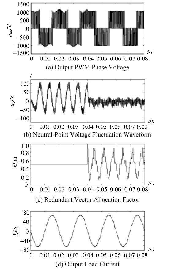
Based on the advantages of easy digital implementation and high voltage utilization, SVPWM is widely used as the modulation algorithm in voltage-source inverters. Reference [14] proposes a three-level SVPWM modulation method with neutral-point potential balancing functionality. In traditional SVPWM neutral-point control methods, the most common approach adjusts the dwell time of redundant small vectors through hysteresis control. The effectiveness of this scheme is closely related to the power factor: the lower the power factor, the less ideal the neutral-point control performance. By exploiting the characteristic that redundant small vectors appear in pairs—each pair generating the same line voltage but opposite-direction neutral-point currents—the traditional control scheme is improved. To verify the effectiveness of the algorithm, simulation experiments were conducted on a three-level inverter experimental platform using the TMS320LF2407A DSP as the core control chip, producing simulated waveforms for neutral-point voltage balancing. As shown in Fig. 7, before t=0.04, when neutral-point control was not applied, both the output PWM phase voltage amplitude and the neutral-point voltage fluctuation waveform exhibited significant variations. After applying the neutral-point algorithm, voltage fluctuations were effectively controlled [14].
2.2. Intermediate-stage DAB
There are generally two control methods for intermediate-stage DAB converters: DC voltage control and phase-shift control [15]. Phase-shift control includes Single Phase Shift (SPS), Dual Phase Shift (DPS), Triple Phase Shift (TPS), and Extended Phase Shift (EPS) methods.
DC voltage control of the DAB involves first converting DC to AC via a full-bridge inverter. The AC is then transferred through a high-frequency transformer and finally converted back to DC by a full-bridge rectifier. Since the RMS value of the AC output voltage of the full-bridge inverter can only be lower than the DC link voltage, this approach significantly limits the voltage regulation range [16].
In contrast, phase-shift control generates high-frequency square waves on the AC sides of the two full-bridge converters. When the magnetizing reactance is disregarded, the DAB circuit can be approximated as two current sources linked through an inductor. Varying the phase shift angle enables regulation of both the amount and direction of power [15] transfer [15]. This approach has been extensively adopted because it facilitates soft switching, exhibits low inertia, and [17] ensures rapid transient performance [17]. The typical modulation techniques applied under this scheme are single-, dual-, triple-, and extended-phase shift strategies.
The traditional Single Phase Shift (SPS) control method is characterized by its simple control structure; however, it suffers from circulating power and is not suitable for DAB control when the input and output voltages are mismatched [18,19]. To address this issue, numerous scholars have conducted research from different perspectives. Reference [20] proposes a Dual Phase Shift (DPS) method for three-level converters, with the phase shift applied on the primary side. Reference [21] presents a DPS control method in which only one bridge arm is phase-shifted, reducing return power. Under a given transmission efficiency, this approach results in lower current stress and conduction losses, thereby improving transmission efficiency. Reference [22] introduces a novel DPS, which adds an additional degree of freedom to the system by adjusting the timing sequence between diagonal semiconductor switch gate signals. Compared with traditional phase-shift control, this method exhibits superior dynamic and static performance and can also limit inrush current during startup. On this basis, Reference [23] establishes a mathematical model of current stress and conducts a detailed quantitative analysis, experimentally verifying the conditions for minimal current stress in all DPS modes, as well as the correctness and advantages of the optimal current control principles and implementation schemes. Triple Phase Shift (TPS) control achieves maximum control freedom at a constant switching frequency by separately controlling the duty cycles of the two full bridges and the phase shift between them. Consequently, both SPS and DPS can be interpreted as particular forms of TPS. In Reference [24], an optimized TPS-based modulation method was proposed, obtained via a unified framework that incorporates all feasible switching states. This approach reduces device current stress and ensures soft-switching across the full operating range, thereby providing a standardized strategy for TPS-controlled DABs.
3. Voltage and power balancing techniques for cascade power electronic transformers
For PETs with either Multilevel Cascaded H-Bridge (MLCHB) rectifier or Modular Multilevel Converter (MMC) topologies, their series-multi-module structure can lead to voltage imbalances if any single module exhibits overvoltage or undervoltage. This may cause uneven voltage distribution at the input or output stages, resulting in local under-voltage or over-voltage conditions, and in severe cases, output waveform distortion. Additionally, both converter types contain a large number of power devices, and inconsistencies in device parameters under synchronized control can also induce voltage drift. When different modules are controlled independently, the accumulation of voltage sampling or control delay errors can further contribute to voltage imbalance. Moreover, power imbalance in the intermediate-stage DAB is one of the causes of voltage imbalance [25]. Therefore, the study of voltage and power balancing control strategies remains a critical and challenging task for the practical application of PETs across various fields.
3.1. MMC
Since its introduction, the MMC has been widely recognized for its modularity and scalability. In recent years, with the increasing demand for long-distance power transmission, MMC has become the preferred topology in high-voltage direct current (HVDC) systems. However, MMC-HVDC faces challenges related to DC-side short circuits. For small-capacity transmission, DC circuit breakers can address this issue, but as capacity increases, the cost and manufacturing complexity of DC breakers rise sharply. Therefore, in widely applied MMC topologies, modified submodules (SMs) are used to handle DC short circuits [26]. Based on this premise, this paper introduces the capacitor voltage balancing control strategies for MMCs.
Most studies adopt direct capacitor voltage balancing control, in which the capacitor voltages within the rectifier bridge arms are first sorted. Based on the sorting results and the direction of the bridge-arm current, the SM switching states are toggled to ON at designated moments [27,28]. Direct capacitor voltage balancing control offers ideal dynamic performance; however, it does not consider switching frequency requirements, resulting in excessively high switching frequencies. Reference [29] optimizes the direct capacitor voltage balancing method. By comparing capacitor voltage levels, the SMs with higher voltages are identified during the bridge-arm current discharge period, increasing their likelihood of being switched ON in the next cycle, while correspondingly increasing the likelihood of switching other SMs OFF. During the charging period of the bridge-arm current, SMs with lower capacitor voltages are required to be switched ON in the next cycle, and SMs with voltages exceeding the lower voltage limit have an increased likelihood of being switched OFF in the next cycle. This method allows rapid adjustment of over-limit capacitor voltages while maintaining the switching states of modules within the safe voltage range, reducing switching losses without significantly increasing capacitor voltage ripple. However, this approach requires a large number of voltage sensors and sorting algorithms, resulting in a substantial data load that burdens the equipment. Reference [30] adopts a level-based control (NLC) approach to simplify the method in [29]. The SMs to be switched ON are sorted according to their number, and during the gate pulse generation stage, the switching state is determined with reference to the capacitor voltage, reducing the computational load by 60% [26]. The above are all active capacitor voltage balancing methods. In addition, passive methods also exist. Reference [31] proposes constructing auxiliary circuits for self-balancing of capacitor voltages. The auxiliary circuit, composed of diodes and inductors, allows the unbalanced energy of adjacent SM modules to be spontaneously transferred through the circuit. Furthermore, the auxiliary circuit has a low rated power, resulting in low losses and cost. Based on this, Reference [26] proposes a novel submodule with a negative output voltage level, enabling the MMC to handle DC short-circuit currents. In summary, the voltage balancing strategies for MMCs are continuously optimized with the goals of simpler computation and lower power consumption. At the same time, depending on the application, efforts are made to simultaneously address the challenges encountered in HVDC transmission systems.
3.2. MLCHB
The voltage and power balancing strategies for PETs with MLCHB topology can be directly realized through modulation techniques. Depending on the spatial positions of the triangular carriers in the modulation scheme, these can be divided into Carrier Disposition (CD) and Carrier Phase-Shift (CPS) methods. Among these modulation techniques, the PSC-PWM strategy has the advantage that the output power of each cascaded H-bridge unit is naturally balanced [32]. PSC-PWM also features low total harmonic distortion (THD), high effective switching frequency, and uniform distribution of power and semiconductor stress among SMs [33]. The IPD-PWM strategy is a variant of CPS-PWM. Under this modulation strategy, the THD of the output line voltage waveform is minimized; however, due to the differing switching times of each cascaded unit, the fundamental amplitude of the output voltage and the output power of each H-bridge unit also differ, resulting in uneven power distribution. Reference [34] proposes a hybrid multi-carrier PWM technique based on carrier reconstruction. The triangular carriers of the IPD-PWM strategy are reconstructed, increasing the number of switching function states from seven to eight (Fig. 8). Redundant switching states can be utilized and carrier positions vertically rearranged so that the voltage characteristics of each H-bridge are modified without altering the output levels. This adjustment promotes equalization of the average output power across cascaded units. Nevertheless, when the number of H-bridges grows, the balancing process becomes slower, and the method still fails to enhance DC-link voltage utilization.
Reference [35] proposes an IPD-TPWM strategy to address low DC-side voltage utilization and uneven output power among cascaded units. In this approach, the sinusoidal waveform of the conventional IPD-PWM strategy is replaced with a trapezoidal pulse-width modulation signal. By analyzing the relationship among DC voltage utilization, total harmonic distortion (THD), and the triangular measurement index δ\deltaδ, the optimal trapezoidal modulation waveform can be determined. The study further compares the output voltage waveforms, phase voltage spectral distributions, and THD values of each unit under the IPD-SPWM and IPD-TPWM strategies. The results demonstrate that the proposed strategy increases DC voltage utilization by up to 19.1% while maintaining power balance across the full modulation index range. However, a limitation of the study is that it does not compare the time required for achieving power balance between the two strategies.
4. Port control techniques for cascade power electronic transformers
The output ports of PETs are often directly connected to a load or integrated into a microgrid. In applications where the load is directly connected, such as locomotive traction systems or non-active distribution networks, providing voltage with stable frequency and amplitude is the primary task of the PET. Typical port-level control techniques comprise V/F regulation, droop-based control, virtual synchronous generator (VSG) methods, and variable-frequency schemes. Among these, droop control governs active and reactive power by imitating the behavior of synchronous machines operating in parallel. Initially introduced for uninterruptible power supply (UPS) systems [36], it has since evolved into a widely adopted solution for inverter parallelization. Reference [37] presents a control method for islanded microgrids or inverters operating in parallel with an infinite bus. The method simulates a voltage source with a complex finite output impedance by controlling the current flowing through a virtual impedance, which is caused by the voltage difference between the virtual AC source and the grid. This approach is equivalent to droop control realized through modified active and reactive power. It not only reduces voltage harmonics but also enables more efficient control of frequency and voltage when line resistance cannot be neglected.
In microgrid applications, droop control usually functions as the primary control in a hierarchical structure. Secondary control is then used to maintain frequency and voltage near their nominal values, as well as to achieve accurate reactive power, harmonic, and unbalanced power distribution [38].
However, in distributed generation (DG) applications, droop control cannot provide inertia support to the power system. This limitation led to the development of the Virtual Synchronous Generator (VSG) method. In the early VSG control techniques, VSG was primarily designed for energy storage systems rather than DGs, treating the energy storage as a dedicated frequency compensator [39,40]. In recent years, VSG control methods for DGs have gradually been developed. Reference [41] improves traditional VSG control by eliminating slow components and major nonlinear elements in the closed-loop system composed of the synchronous unit, inverter controller, and power system, which affect synchronization speed and accuracy, thereby constructing a new controller. A common issue with the above approaches is that they require a complete synchronous generator (SG) model in the computations, making the algorithm complex and typically consuming a large portion of processor capacity. Reference [42] extracts the basic elements of VSG and directly solves the rotor frequency through iteration of the swing equation, significantly reducing computational load.
Reference [43] compares the dynamic characteristics of droop control and VSG control, providing a comprehensive analysis of the differences between the two control schemes caused by the presence of the swing equation.
Reference [43] establishes small-signal models for both islanded operation mode and SG-connected mode. Using these models, the step response of frequency variations during load transients can be calculated.
During simulations in islanded mode, the results of droop control exhibit observable ripple, which in practical applications requires the use of filters to eliminate. Regarding frequency variations, DGs under VSG control respond more slowly, while DGs under droop control exhibit almost no inertia. The operating results in SG-connected mode are similar to those in islanded mode. The results indicate that distributed generators using droop control contribute greater inertia to the system compared to those using VSG control, while the parameters of the swing equation have no effect on the steady-state performance.
Next, the effects of delays in the governor and P-droop controllers are compared between the two control methods. When constructing the governor and P-droop controllers for both control schemes, parameter substitutions are required because the input and output directions are reversed in P–ω droop regulation. In VSG control, the output is active power and the input is frequency; in droop control, the input is active power and the output is frequency. Simulation results show that delays cause the system frequency under VSG control to change more rapidly, whereas the system frequency under droop control changes more slowly.
5. Conclusion
This paper discusses the current development status of cascade power electronic transformers (PETs) from three aspects: modulation techniques, voltage and power balancing strategies, and port control techniques. Currently, cascade PETs demonstrate broad application prospects in renewable energy integration, power transmission, and rail transportation due to their modularity, high-voltage adaptability, and excellent scalability. Although considerable progress has been made in recent research, cascade PETs still face multiple challenges in system stability, efficiency optimization, and fault-tolerant capability, such as inconsistencies among power module parameters, voltage imbalance, and complex control systems. Based on a comprehensive analysis of the development process and existing technologies of cascade PETs, their future development can be directed in the following areas:
(1) Topology optimization.The most common topologies are MMC and MLCHB, each with unresolved challenges. The modularity of MMC provides unparalleled advantages in high-voltage adaptability, production, application, maintenance, and scalability. However, the large number of cascaded modules results in a bulky system, limiting practical applicability. MLCHB enhances fault tolerance and offers flexible control methods through the addition of H-bridge units, but the system scale expands rapidly, increasing the coordination complexity. Both topologies face challenges of complex and cumbersome control algorithms.
(2) Intelligent control for voltage and power balancing.Most voltage and power balancing methods still rely on stabilizing output voltage waveforms through modulation techniques or by controlling the switching states of power devices. These methods often require substantial computational resources and, in the event of faults, can only mitigate losses by shutting down some or all modules. With the recent development of artificial intelligence, technologies such as digital twins and reinforcement learning can be introduced to partially replace conventional control algorithms, reducing computational demands on controllers.
(3) Innovation in power device materials.Cascade PETs contain numerous power devices, and their control precision and output stability heavily depend on these devices. Most PET failures result from overcurrent or overload of power devices. Future PETs can utilize wide-bandgap devices made of semiconductor materials such as SiC and GaN to replace traditional IGBTs, thereby improving conversion efficiency and switching frequency. At the same time, the development of high-performance magnetic materials is crucial. Currently, the most common core material is MnZn ferrite, which has medium permeability, is suitable for medium-frequency conversion, and is low-cost and mature in production. However, ferrite materials have low saturation flux density and large temperature drift, which severely limits their application in high-frequency transformers. Nanocrystalline alloys are currently the most suitable core materials for high-frequency transformers, offering very low high-frequency loss and enabling the same induced voltage in a smaller volume, thus increasing PET power density and reducing the overall size of PETs.
References
[1]. Li, Z. X., Gao, F. Q., Zhao, C., et al. (2018). A review of research on power electronic transformer technology. Proceedings of the Chinese Society for Electrical Engineering, 38(5), 1274–1289. https: //doi.org/10.13334/j.0258-8013.pcsee.172575
[2]. Li, X., Hao, R. X., You, X. J., et al. (2017). A DC voltage balancing control strategy for cascaded power electronic transformers. Transactions of China Electrotechnical Society, 32(2), 238–245. https: //doi.org/10.19595/j.cnki.1000-6753.tces.2017.02.027
[3]. Ronan, E. R., Sudhoff, S. D., Glover, S. F., & Galloway, D. L. (2000). Application of power electronics to the distribution transformer. In APEC 2000: Fifteenth Annual IEEE Applied Power Electronics Conference and Exposition (Vol. 2, pp. 861–867). New Orleans, LA, USA. https: //doi.org/10.1109/APEC.2000.822606
[4]. Xiao, F. (2018). Optimization control and application research of cascaded power electronic transformers (Master’s thesis, Hunan University).
[5]. Wang, S. S., Wang, Y. B., Lin, Y. F., et al. (2016). Voltage and power balancing control methods for cascaded power electronic transformers. Transactions of China Electrotechnical Society, 31(22), 92–99. https: //doi.org/10.19595/j.cnki.1000-6753.tces.2016.22.012
[6]. Wang, S. S., Zhou, X. X., Tang, G. F., et al. (2011). Overcurrent analysis of submodules under DC bipolar short-circuit in modular multilevel converter HVDC systems. Proceedings of the Chinese Society for Electrical Engineering, 31(1), 1–7. https: //doi.org/10.13334/j.0258-8013.pcsee.2011.01.001
[7]. Zhang, J. (2014). Study on diode clamped three-level inverter based on carrier modulation (Master’s thesis, Huazhong University of Science and Technology).
[8]. Li, Y. D., Gao, Y., & Hou, X. (2005). Current status and progress of PWM control technology for large-capacity multilevel converters. Power Electronics Technology, (5), 5–9.
[9]. Liu, Z., et al. (2022). Research on high frequency vibration reduction using carrier phase shifted PWM for 4-module 3-phase permanent magnet synchronous motor. IEEE Transactions on Industry Applications, 58(6), 7192–7200. https: //doi.org/10.1109/TIA.2022.3198630
[10]. Miyama, Y., et al. (2018). Vibration reduction by applying carrier phase-shift PWM on dual three-phase winding permanent magnet synchronous motor. IEEE Transactions on Industry Applications, 54, 5998–6004.
[11]. Long, Q. J., Hu, L. D., Lu, B., et al. (2025). Analysis and suppression of neutral line current abnormal increase in three-level H-bridge inverter considering high-frequency vibration of multiphase motors. Proceedings of the Chinese Society for Electrical Engineering, 1–15. https: //doi.org/10.13334/j.0258-8013.pcsee.242056
[12]. Tu, Q., Xu, Z., & Xu, L. (2011). Reduced switching-frequency modulation and circulating current suppression for modular multilevel converters. IEEE Transactions on Power Delivery, 26(3), 2009–2017. https: //doi.org/10.1109/TPWRD.2011.2115258
[13]. Xiong, J., Kang, Y., Zhang, K., et al. (1999). Comparative study of voltage space vector modulation and conventional SPWM. Power Electronics Technology, (1), 25–28.
[14]. Song, W. X., Chen, G. C., Wu, H., et al. (2006). Three-level space vector modulation with midpoint voltage balancing function and its implementation. Proceedings of the Chinese Society for Electrical Engineering, (12), 95–100.
[15]. Zhao, B., An, F., Song, Q., et al. (2021). Development and application of dual active bridge DC transformer. Proceedings of the Chinese Society for Electrical Engineering, 41(01), 288–298+418. https: //doi.org/10.13334/j.0258-8013.pcsee.201635
[16]. Chung, I.-Y., et al. (2009). Integration of a bi-directional DC–DC converter model into a large-scale system simulation of a shipboard MVDC power system. In 2009 IEEE Electric Ship Technologies Symposium (pp. 318–325). Baltimore, MD, USA. https: //doi.org/10.1109/ESTS.2009.4906531
[17]. Liu, D., & Li, H. (2006). A ZVS bi-directional DC–DC converter for multiple energy storage elements. IEEE Transactions on Power Electronics, 21(5), 1513–1517. https: //doi.org/10.1109/TPEL.2006.882450
[18]. De Doncker, R. W. A. A., Divan, D. M., & Kheraluwala, M. H. (1991). A three-phase soft-switched high-power-density DC/DC converter for high-power applications. IEEE Transactions on Industry Applications, 27(1), 63–73. https: //doi.org/10.1109/28.67533
[19]. Xie, Y., Sun, J., & Freudenberg, J. S. (2010). Power flow characterization of a bidirectional galvanically isolated high-power DC/DC converter over a wide operating range. IEEE Transactions on Power Electronics, 25(1), 54–66. https: //doi.org/10.1109/TPEL.2009.2024151
[20]. Zhang, Z., & Ruan, X. (2005). A novel double phase-shift control scheme for full-bridge three-level converter. In Twentieth Annual IEEE Applied Power Electronics Conference and Exposition (Vol. 2, pp. 1240–1245). Austin, TX, USA. https: //doi.org/10.1109/APEC.2005.1453162
[21]. Zhao, B., Yu, Q. G., & Sun, W. X. (2012). Analysis of bidirectional full-bridge DC–DC converter with double phase-shift control and its power backflow characteristics. Proceedings of the Chinese Society for Electrical Engineering, 32(12), 43–50. https: //doi.org/10.13334/j.0258-8013.pcsee.2012.12.008
[22]. Bai, H., & Mi, C. (2008). Eliminate reactive power and increase system efficiency of isolated bidirectional dual-active-bridge DC–DC converters using novel dual-phase-shift control. IEEE Transactions on Power Electronics, 23(6), 2905–2914. https: //doi.org/10.1109/TPEL.2008.2005103
[23]. Wang, Y. B., Wang, S. S., Feng, B., et al. (2015). Optimal current control of dual-active DC–DC converters based on double phase-shift control. Transactions of China Electrotechnical Society, 30(14), 488–496. https: //doi.org/10.19595/j.cnki.1000-6753.tces.2015.14.066
[24]. Huang, J., Wang, Y., Li, Z., & Lei, W. (2016). Unified triple-phase-shift control to minimize current stress and achieve full soft-switching of isolated bidirectional DC–DC converter. IEEE Transactions on Industrial Electronics, 63, 4169–4179.
[25]. Zheng, T., Wang, K., Zheng, Z. D., et al. (2022). Review on power electronic transformers based on MMC topology. Proceedings of the Chinese Society for Electrical Engineering, 42(15), 5630–5649. https: //doi.org/10.13334/j.0258-8013.pcsee.220315
[26]. Huang, J., Li, K., Ye, Y., Wang, X., & Han, W. (2024). Novel hybrid modular multilevel converter with capacitor voltages self-balancing and DC-fault blocking abilities for MMC-HVDC. In IECON 2024 - 50th Annual Conference of the IEEE Industrial Electronics Society (pp. 1–6). Chicago, IL, USA. https: //doi.org/10.1109/IECON55916.2024.10905097
[27]. Gemmell, B., Dorn, J., Retzmann, D., & Soerangr, D. (2008). Prospects of multilevel VSC technologies for power transmission. In 2008 IEEE/PES Transmission and Distribution Conference and Exposition (pp. 1–16). Chicago, IL, USA. https: //doi.org/10.1109/TDC.2008.4517192
[28]. Saeedifard, M., & Iravani, R. (2010). Dynamic performance of a modular multilevel back-to-back HVDC system. IEEE Transactions on Power Delivery, 25(4), 2903–2912. https: //doi.org/10.1109/TPWRD.2010.2050787
[29]. Guan, M., Xu, Z., & Chen, H. (2011). Control and modulation strategies for modular multilevel converter based HVDC system. In IECON 2011 - 37th Annual Conference of the IEEE Industrial Electronics Society (pp. 849–854). Melbourne, VIC, Australia. https: //doi.org/10.1109/IECON.2011.6119421
[30]. Meshram, P. M., & Borghate, V. B. (2015). A simplified nearest level control (NLC) voltage balancing method for modular multilevel converter (MMC). IEEE Transactions on Power Electronics, 30(1), 450–462. https: //doi.org/10.1109/TPEL.2014.2317705
[31]. Zheng, T., et al. (2021). A novel Z-type modular multilevel converter with capacitor voltage self-balancing for grid-tied applications. IEEE Transactions on Power Electronics, 36(2), 1399–1411. https: //doi.org/10.1109/TPEL.2020.2997991
[32]. Li, Y., Wang, Y., & Li, B. Q. (2016). Generalized theory of phase-shifted carrier PWM for cascaded H-bridge converters and modular multilevel converters. IEEE Journal of Emerging and Selected Topics in Power Electronics, 4(2), 589–605. https: //doi.org/10.1109/JESTPE.2015.2476699
[33]. Sekiguchi, K., Khamphakdi, P., Hagiwara, M., & Akagi, H. (2014). A grid-level high-power BTB (back-to-back) system using modular multilevel cascade converters without common DC-link capacitor. IEEE Transactions on Industry Applications, 50(4), 2648–2659. https: //doi.org/10.1109/TIA.2013.2290867
[34]. Ye, M., Chen, L., Kang, L., Li, S., Zhang, J., & Wu, H. (2019). Hybrid multi-carrier PWM technique based on carrier reconstruction for cascaded H-bridge inverter. IEEE Access, 7, 53152–53162. https: //doi.org/10.1109/ACCESS.2019.2912216
[35]. Ye, M., Ren, W., Chen, L., Wei, Q., Song, G., & Li, S. (2019). Research on power-balance control strategy of CHB multilevel inverter based on TPWM. IEEE Access, 7, 157226–157240. https: //doi.org/10.1109/ACCESS.2019.2950064
[36]. Chandorkar, M. C., Divan, D. M., & Adapa, R. (1993). Control of parallel connected inverters in standalone AC supply systems. IEEE Transactions on Industry Applications, 29(1), 136–143. https: //doi.org/10.1109/28.195899
[37]. De Brabandere, K., Bolsens, B., Van den Keybus, J., Woyte, A., Driesen, J., & Belmans, R. (2007). A voltage and frequency droop control method for parallel inverters. IEEE Transactions on Power Electronics, 22(4), 1107–1115. https: //doi.org/10.1109/TPEL.2007.900456
[38]. Micallef, A., Apap, M., Spiteri-Staines, C., Guerrero, J. M., & Vasquez, J. C. (2014). Reactive power sharing and voltage harmonic distortion compensation of droop controlled single-phase islanded microgrids. IEEE Transactions on Smart Grid, 5(3), 1149–1158. https: //doi.org/10.1109/TSG.2013.2291912
[39]. Delille, G., Francois, B., & Malarange, G. (2012). Dynamic frequency control support by energy storage to reduce the impact of wind and solar generation on isolated power system's inertia. IEEE Transactions on Sustainable Energy, 3(4), 931–939. https: //doi.org/10.1109/TSTE.2012.2205025
[40]. Torres L., M. A., Lopes, L. A. C., Morán T., L. A., & Espinoza C., J. R. (2014). Self-tuning virtual synchronous machine: A control strategy for energy storage systems to support dynamic frequency control. IEEE Transactions on Energy Conversion, 29(4), 833–840. https: //doi.org/10.1109/TEC.2014.2362577
[41]. Zhong, Q.-C., Nguyen, P.-L., Ma, Z., & Sheng, W. (2014). Self-synchronized synchronverters: Inverters without a dedicated synchronization unit. IEEE Transactions on Power Electronics, 29(2), 617–630. https: //doi.org/10.1109/TPEL.2013.2258684
[42]. Alipoor, J., Miura, Y., & Ise, T. (2015). Power system stabilization using virtual synchronous generator with alternating moment of inertia. IEEE Journal of Emerging and Selected Topics in Power Electronics, 3(2), 451–458. https: //doi.org/10.1109/JESTPE.2014.2362530
[43]. Liu, J., Miura, Y., & Ise, T. (2016). Comparison of dynamic characteristics between virtual synchronous generator and droop control in inverter-based distributed generators. IEEE Transactions on Power Electronics, 31(5), 3600–3611. https: //doi.org/10.1109/TPEL.2015.2465852
Cite this article
Wu,X. (2025). Cascade Control Strategies for Power Electronic Transformers. Applied and Computational Engineering,180,46-62.
Data availability
The datasets used and/or analyzed during the current study will be available from the authors upon reasonable request.
Disclaimer/Publisher's Note
The statements, opinions and data contained in all publications are solely those of the individual author(s) and contributor(s) and not of EWA Publishing and/or the editor(s). EWA Publishing and/or the editor(s) disclaim responsibility for any injury to people or property resulting from any ideas, methods, instructions or products referred to in the content.
About volume
Volume title: Proceedings of CONF-MCEE 2026 Symposium: Advances in Sustainable Aviation and Aerospace Vehicle Automation
© 2024 by the author(s). Licensee EWA Publishing, Oxford, UK. This article is an open access article distributed under the terms and
conditions of the Creative Commons Attribution (CC BY) license. Authors who
publish this series agree to the following terms:
1. Authors retain copyright and grant the series right of first publication with the work simultaneously licensed under a Creative Commons
Attribution License that allows others to share the work with an acknowledgment of the work's authorship and initial publication in this
series.
2. Authors are able to enter into separate, additional contractual arrangements for the non-exclusive distribution of the series's published
version of the work (e.g., post it to an institutional repository or publish it in a book), with an acknowledgment of its initial
publication in this series.
3. Authors are permitted and encouraged to post their work online (e.g., in institutional repositories or on their website) prior to and
during the submission process, as it can lead to productive exchanges, as well as earlier and greater citation of published work (See
Open access policy for details).
References
[1]. Li, Z. X., Gao, F. Q., Zhao, C., et al. (2018). A review of research on power electronic transformer technology. Proceedings of the Chinese Society for Electrical Engineering, 38(5), 1274–1289. https: //doi.org/10.13334/j.0258-8013.pcsee.172575
[2]. Li, X., Hao, R. X., You, X. J., et al. (2017). A DC voltage balancing control strategy for cascaded power electronic transformers. Transactions of China Electrotechnical Society, 32(2), 238–245. https: //doi.org/10.19595/j.cnki.1000-6753.tces.2017.02.027
[3]. Ronan, E. R., Sudhoff, S. D., Glover, S. F., & Galloway, D. L. (2000). Application of power electronics to the distribution transformer. In APEC 2000: Fifteenth Annual IEEE Applied Power Electronics Conference and Exposition (Vol. 2, pp. 861–867). New Orleans, LA, USA. https: //doi.org/10.1109/APEC.2000.822606
[4]. Xiao, F. (2018). Optimization control and application research of cascaded power electronic transformers (Master’s thesis, Hunan University).
[5]. Wang, S. S., Wang, Y. B., Lin, Y. F., et al. (2016). Voltage and power balancing control methods for cascaded power electronic transformers. Transactions of China Electrotechnical Society, 31(22), 92–99. https: //doi.org/10.19595/j.cnki.1000-6753.tces.2016.22.012
[6]. Wang, S. S., Zhou, X. X., Tang, G. F., et al. (2011). Overcurrent analysis of submodules under DC bipolar short-circuit in modular multilevel converter HVDC systems. Proceedings of the Chinese Society for Electrical Engineering, 31(1), 1–7. https: //doi.org/10.13334/j.0258-8013.pcsee.2011.01.001
[7]. Zhang, J. (2014). Study on diode clamped three-level inverter based on carrier modulation (Master’s thesis, Huazhong University of Science and Technology).
[8]. Li, Y. D., Gao, Y., & Hou, X. (2005). Current status and progress of PWM control technology for large-capacity multilevel converters. Power Electronics Technology, (5), 5–9.
[9]. Liu, Z., et al. (2022). Research on high frequency vibration reduction using carrier phase shifted PWM for 4-module 3-phase permanent magnet synchronous motor. IEEE Transactions on Industry Applications, 58(6), 7192–7200. https: //doi.org/10.1109/TIA.2022.3198630
[10]. Miyama, Y., et al. (2018). Vibration reduction by applying carrier phase-shift PWM on dual three-phase winding permanent magnet synchronous motor. IEEE Transactions on Industry Applications, 54, 5998–6004.
[11]. Long, Q. J., Hu, L. D., Lu, B., et al. (2025). Analysis and suppression of neutral line current abnormal increase in three-level H-bridge inverter considering high-frequency vibration of multiphase motors. Proceedings of the Chinese Society for Electrical Engineering, 1–15. https: //doi.org/10.13334/j.0258-8013.pcsee.242056
[12]. Tu, Q., Xu, Z., & Xu, L. (2011). Reduced switching-frequency modulation and circulating current suppression for modular multilevel converters. IEEE Transactions on Power Delivery, 26(3), 2009–2017. https: //doi.org/10.1109/TPWRD.2011.2115258
[13]. Xiong, J., Kang, Y., Zhang, K., et al. (1999). Comparative study of voltage space vector modulation and conventional SPWM. Power Electronics Technology, (1), 25–28.
[14]. Song, W. X., Chen, G. C., Wu, H., et al. (2006). Three-level space vector modulation with midpoint voltage balancing function and its implementation. Proceedings of the Chinese Society for Electrical Engineering, (12), 95–100.
[15]. Zhao, B., An, F., Song, Q., et al. (2021). Development and application of dual active bridge DC transformer. Proceedings of the Chinese Society for Electrical Engineering, 41(01), 288–298+418. https: //doi.org/10.13334/j.0258-8013.pcsee.201635
[16]. Chung, I.-Y., et al. (2009). Integration of a bi-directional DC–DC converter model into a large-scale system simulation of a shipboard MVDC power system. In 2009 IEEE Electric Ship Technologies Symposium (pp. 318–325). Baltimore, MD, USA. https: //doi.org/10.1109/ESTS.2009.4906531
[17]. Liu, D., & Li, H. (2006). A ZVS bi-directional DC–DC converter for multiple energy storage elements. IEEE Transactions on Power Electronics, 21(5), 1513–1517. https: //doi.org/10.1109/TPEL.2006.882450
[18]. De Doncker, R. W. A. A., Divan, D. M., & Kheraluwala, M. H. (1991). A three-phase soft-switched high-power-density DC/DC converter for high-power applications. IEEE Transactions on Industry Applications, 27(1), 63–73. https: //doi.org/10.1109/28.67533
[19]. Xie, Y., Sun, J., & Freudenberg, J. S. (2010). Power flow characterization of a bidirectional galvanically isolated high-power DC/DC converter over a wide operating range. IEEE Transactions on Power Electronics, 25(1), 54–66. https: //doi.org/10.1109/TPEL.2009.2024151
[20]. Zhang, Z., & Ruan, X. (2005). A novel double phase-shift control scheme for full-bridge three-level converter. In Twentieth Annual IEEE Applied Power Electronics Conference and Exposition (Vol. 2, pp. 1240–1245). Austin, TX, USA. https: //doi.org/10.1109/APEC.2005.1453162
[21]. Zhao, B., Yu, Q. G., & Sun, W. X. (2012). Analysis of bidirectional full-bridge DC–DC converter with double phase-shift control and its power backflow characteristics. Proceedings of the Chinese Society for Electrical Engineering, 32(12), 43–50. https: //doi.org/10.13334/j.0258-8013.pcsee.2012.12.008
[22]. Bai, H., & Mi, C. (2008). Eliminate reactive power and increase system efficiency of isolated bidirectional dual-active-bridge DC–DC converters using novel dual-phase-shift control. IEEE Transactions on Power Electronics, 23(6), 2905–2914. https: //doi.org/10.1109/TPEL.2008.2005103
[23]. Wang, Y. B., Wang, S. S., Feng, B., et al. (2015). Optimal current control of dual-active DC–DC converters based on double phase-shift control. Transactions of China Electrotechnical Society, 30(14), 488–496. https: //doi.org/10.19595/j.cnki.1000-6753.tces.2015.14.066
[24]. Huang, J., Wang, Y., Li, Z., & Lei, W. (2016). Unified triple-phase-shift control to minimize current stress and achieve full soft-switching of isolated bidirectional DC–DC converter. IEEE Transactions on Industrial Electronics, 63, 4169–4179.
[25]. Zheng, T., Wang, K., Zheng, Z. D., et al. (2022). Review on power electronic transformers based on MMC topology. Proceedings of the Chinese Society for Electrical Engineering, 42(15), 5630–5649. https: //doi.org/10.13334/j.0258-8013.pcsee.220315
[26]. Huang, J., Li, K., Ye, Y., Wang, X., & Han, W. (2024). Novel hybrid modular multilevel converter with capacitor voltages self-balancing and DC-fault blocking abilities for MMC-HVDC. In IECON 2024 - 50th Annual Conference of the IEEE Industrial Electronics Society (pp. 1–6). Chicago, IL, USA. https: //doi.org/10.1109/IECON55916.2024.10905097
[27]. Gemmell, B., Dorn, J., Retzmann, D., & Soerangr, D. (2008). Prospects of multilevel VSC technologies for power transmission. In 2008 IEEE/PES Transmission and Distribution Conference and Exposition (pp. 1–16). Chicago, IL, USA. https: //doi.org/10.1109/TDC.2008.4517192
[28]. Saeedifard, M., & Iravani, R. (2010). Dynamic performance of a modular multilevel back-to-back HVDC system. IEEE Transactions on Power Delivery, 25(4), 2903–2912. https: //doi.org/10.1109/TPWRD.2010.2050787
[29]. Guan, M., Xu, Z., & Chen, H. (2011). Control and modulation strategies for modular multilevel converter based HVDC system. In IECON 2011 - 37th Annual Conference of the IEEE Industrial Electronics Society (pp. 849–854). Melbourne, VIC, Australia. https: //doi.org/10.1109/IECON.2011.6119421
[30]. Meshram, P. M., & Borghate, V. B. (2015). A simplified nearest level control (NLC) voltage balancing method for modular multilevel converter (MMC). IEEE Transactions on Power Electronics, 30(1), 450–462. https: //doi.org/10.1109/TPEL.2014.2317705
[31]. Zheng, T., et al. (2021). A novel Z-type modular multilevel converter with capacitor voltage self-balancing for grid-tied applications. IEEE Transactions on Power Electronics, 36(2), 1399–1411. https: //doi.org/10.1109/TPEL.2020.2997991
[32]. Li, Y., Wang, Y., & Li, B. Q. (2016). Generalized theory of phase-shifted carrier PWM for cascaded H-bridge converters and modular multilevel converters. IEEE Journal of Emerging and Selected Topics in Power Electronics, 4(2), 589–605. https: //doi.org/10.1109/JESTPE.2015.2476699
[33]. Sekiguchi, K., Khamphakdi, P., Hagiwara, M., & Akagi, H. (2014). A grid-level high-power BTB (back-to-back) system using modular multilevel cascade converters without common DC-link capacitor. IEEE Transactions on Industry Applications, 50(4), 2648–2659. https: //doi.org/10.1109/TIA.2013.2290867
[34]. Ye, M., Chen, L., Kang, L., Li, S., Zhang, J., & Wu, H. (2019). Hybrid multi-carrier PWM technique based on carrier reconstruction for cascaded H-bridge inverter. IEEE Access, 7, 53152–53162. https: //doi.org/10.1109/ACCESS.2019.2912216
[35]. Ye, M., Ren, W., Chen, L., Wei, Q., Song, G., & Li, S. (2019). Research on power-balance control strategy of CHB multilevel inverter based on TPWM. IEEE Access, 7, 157226–157240. https: //doi.org/10.1109/ACCESS.2019.2950064
[36]. Chandorkar, M. C., Divan, D. M., & Adapa, R. (1993). Control of parallel connected inverters in standalone AC supply systems. IEEE Transactions on Industry Applications, 29(1), 136–143. https: //doi.org/10.1109/28.195899
[37]. De Brabandere, K., Bolsens, B., Van den Keybus, J., Woyte, A., Driesen, J., & Belmans, R. (2007). A voltage and frequency droop control method for parallel inverters. IEEE Transactions on Power Electronics, 22(4), 1107–1115. https: //doi.org/10.1109/TPEL.2007.900456
[38]. Micallef, A., Apap, M., Spiteri-Staines, C., Guerrero, J. M., & Vasquez, J. C. (2014). Reactive power sharing and voltage harmonic distortion compensation of droop controlled single-phase islanded microgrids. IEEE Transactions on Smart Grid, 5(3), 1149–1158. https: //doi.org/10.1109/TSG.2013.2291912
[39]. Delille, G., Francois, B., & Malarange, G. (2012). Dynamic frequency control support by energy storage to reduce the impact of wind and solar generation on isolated power system's inertia. IEEE Transactions on Sustainable Energy, 3(4), 931–939. https: //doi.org/10.1109/TSTE.2012.2205025
[40]. Torres L., M. A., Lopes, L. A. C., Morán T., L. A., & Espinoza C., J. R. (2014). Self-tuning virtual synchronous machine: A control strategy for energy storage systems to support dynamic frequency control. IEEE Transactions on Energy Conversion, 29(4), 833–840. https: //doi.org/10.1109/TEC.2014.2362577
[41]. Zhong, Q.-C., Nguyen, P.-L., Ma, Z., & Sheng, W. (2014). Self-synchronized synchronverters: Inverters without a dedicated synchronization unit. IEEE Transactions on Power Electronics, 29(2), 617–630. https: //doi.org/10.1109/TPEL.2013.2258684
[42]. Alipoor, J., Miura, Y., & Ise, T. (2015). Power system stabilization using virtual synchronous generator with alternating moment of inertia. IEEE Journal of Emerging and Selected Topics in Power Electronics, 3(2), 451–458. https: //doi.org/10.1109/JESTPE.2014.2362530
[43]. Liu, J., Miura, Y., & Ise, T. (2016). Comparison of dynamic characteristics between virtual synchronous generator and droop control in inverter-based distributed generators. IEEE Transactions on Power Electronics, 31(5), 3600–3611. https: //doi.org/10.1109/TPEL.2015.2465852