


1. Introduction
In recent years, more and more new concepts and new products like 5th generation mobile networks communication technology has been implemented. Lower latency and higher transmission rates have made the interconnection of everything possible. As the front-end device of the receiver, the noise, bandwidth, gain and other indicators of the low-noise amplifier Low-Noise Amplifier have also increased the requirements. Therefore, it is necessary to summarize Low-Noise Amplifier-related technologies and applications so far, which will help researchers and companies summarize past experiences and explore possible innovation directions.
This paper analyzes and summarizes the development and application of low-noise amplifiers. Firstly, the author introduces the background and significance of the topic, and explains the importance of Low-Noise Amplifier in today’s radio frequency field. Next, the author introduces the types and principles, main performance indicators and basic circuit structure of basic amplifiers. The author also introduces the five important performance indicators of low-noise amplifiers: noise figure, impedance matching, linearity, stability and gain, including the physical meaning, application significance and measurement indicators of these indicators. After that, the author analyzes the application scenarios of low-noise amplifiers. Combining the performance characteristics of low-noise amplifiers and the performance requirements in different fields, the design and application cases in the fields of radio astronomy, navigation systems and 5th generation mobile networks communications are introduced. At last, the author draws a conclusion of this paper, as well as introduces future challenges and prospects.
2. Low Noise Amplifier
2.1. Typical Amplifier
2.1.1. Classification. Transistor amplifiers can be divided into bipolar junction transistors and field-effect transistors, or known as unipolar transistors. When a bipolar transistor is working, the internal current is formed by two kinds of carriers, electrons and holes. When a unipolar transistor is working, only electrons move inside to form current. Field effect transistors can be divided into Junction Field-Effect Transistor and Insulated Gate Field-Effect Transistor. Among the latter, Metal Oxide Semiconductor Field-Effect Transistor is currently widely used in various circuits.
2.1.2. Characteristics. There are many performance indicators of amplifiers, and the indicators considered when applied in different fields are also different. There are eight main parameters to consider when designing an amplifier: gain, linearity, noise, power consumption, input and output impedance, speed, voltage swing, and power supply voltage. In practical applications, these characteristics have a mutually restrictive relationship, which results in amplifier design often being a comprehensive optimization problem. Sometimes it is necessary to rely on intuition and experience to get a better solution.
2.1.3. Circuits. For commonly used Complementary Metal Oxide Semiconductor transistors, there are four basic circuit structures: common-source, common-gate, source follower, and Cascode is shown in figure 1, which can provide different characterisitics and design trade-off. Therefore, designers will choose different circuits according to their needs [1]. On the basis of these structures, more circuit forms can be formed by adding or reducing loads, changing load types, changing bias methods, or connecting multiple circuit structures to each other.
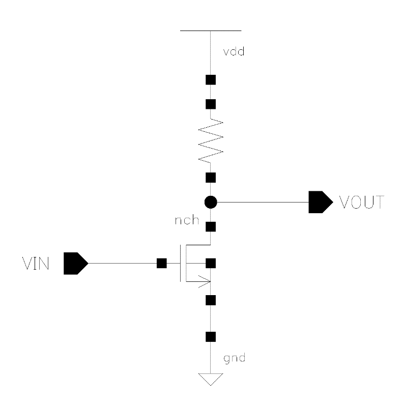
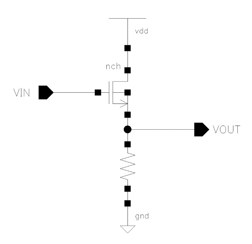
(a) (b)

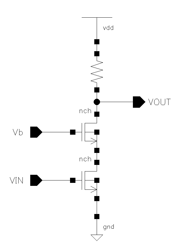
(c) (d)
Figure 1. Common-source, common-gate, source follower, and Cascode circuit [1].
2.2. Characteristics Analysis of Low-Noise Amplifier
As a first-stage amplifier in the receiver, Low-Noise Amplifier’s various performances will have a direct impact on the communication quality of the receiver. Generally speaking, the most critical performance indicators of Low-Noise Amplifier include gain, isolation, noise figure, linearity and stability. Other indicators include return loss, power consumption, chip area and power capacity, etc. During the progress of design, various indicators are interconnected and restrict each other, and the use of different processes will also show obvious performance differences [2]. Therefore, an in-depth understanding of each indicator is very helpful for Low-Noise Amplifier design.
Noise Figure. The Signal to Noise Ratio worsens because of the generated noise, after the signal transfers through the amplifier. The multiple by which the Signal to Noise Ratio decreases is defined as the noise figure:
\( {N_{f}}=\frac{{S_{in}}/{N_{in}}}{{S_{out}}/{N_{out}}} \) (1)
In the equation, Sin and Nin respectively refer to the signal and noise power at the input end of the low-noise amplifier; while Sout and Nout respectively refer to the two characteristics at the output end of the low-noise amplifier [3].
With the advancement of microwave transistor process technology, the noise figures of field effect transistors Metal Oxide Semiconductor Field-Effect Transistor and high electron mobility transistors High Electron Mobility Transistor continue to decrease. It is not convenient to apply the noise figure expression method when it is small, so people use the equivalent noise temperature instead. It means the temperature the resistance of the signal source should be at, when it can produce the same amount of noise output power generated by the actual amplifier. The relationship between the equivalent noise temperature and the noise figure is as follows:
\( F=1+\frac{{T_{e}}}{T} \) (2) \( {T_{e}}=T({N_{f}}-1) \) (3)
In the formula, T is the ambient temperature, usually taken as 293K.
2.2.1. Impedance Matching. The Low-Noise Amplifier is often the module placed in the first stage in the receiver, so the input terminal is connected to the antenna terminal or the radio frequency filter output terminal. If the ports do not match, the signal output by the antenna terminal or radio frequency filter output terminal Reflection will occur at the input end of the Low-Noise Amplifier, affecting the signal power received and deteriorating the system performance. Therefore, the input matching of the Low-Noise Amplifier is a very neccesary indicator [4].
In the receiver, the downstream module of the low-noise amplifier is a mixer. Generally, the input impedance of the mixer is very large, so there is no need to match the output of the low-noise amplifier.
Voltage Standing Wave Ratio can be used to determine whether the impedance matches. When measuring the input and output ports of an amplifier, its standing wave ratio must be less than a specific value. Voltage Standing Wave Ratio of the input and output ports of the system is:
\( {VSWR_{in}}=\frac{1+|{Γ_{in}}|}{1-|{Γ_{in}}|} \) (4) \( {VSWR_{out}}=\frac{1+|{Γ_{out}}|}{1-|{Γ_{out}}|} \) (5)
Γin and Γout are the reflection coefficients respectively.
2.2.2. Linearity. In receivers, the nonlinearity produced by circuit components has a very obvious impact on communication quality. Linearity is often used to describe the circuit’s large signal processing capabilities.
For an amplifier, its power gain means the ratio of output power to input power. When output power increases, the amplifier’s transfer function becomes nonlinear, that is, the output power is lower than expected from the small signal gain. This characteristic causes distortion in the amplified signal. The output power that causes the gain to drop to 1dB below the linear gain is called the 1dB compression point.
Another phenomenon caused by nonlinearity is intermodulation: when the low-noise amplifier is in the nonlinear region, cross-combination frequencies are generated between the frequency spectrum components of the microwave signal, resulting in cross-interference.
In order to qualitatively measure cross-interference, the harmonic components generated by the two sinusoidal signal spectral components are usually used for quantitative analysis. We generally care about third-order intermodulation. If two sinusoidal signals with similar frequencies are added to the amplifier, their angular frequencies are ω1 and ω2 respectively, the ratio of the third-order intermodulation power P3 to the power P1 of ω1 or ω2 is called the third-order intermodulation coefficient.
2.2.3. Stability. When designing a Low-Noise Amplifier, the stability and non-oscillation of the circuit is the prerequisite for the realization of all other indicators. The Low-Noise Amplifier is usually at the forefront of the receiving system. Its input terminal is connected to the external environment. The source impedance often changes randomly. Under certain operating frequencies and terminal conditions, the radio frequency circuit may produce “self-excitation”, causing the amplifier to Not working properly or even damaged [5].
Therefore, achieving unconditional stability at any source impedance and at any frequency is a design premise. Only in an unconditionally stable state, other performance indicators of the amplifier are meaningful. The conditions for judging the absolute stability of the circuit are:
\( k=\frac{1-{|{S_{11}}|^{2}}-{|{S_{22}}|^{2}}+{|Δ|^{2}}}{2|{S_{12}}||{S_{21}}|} \gt 1 \) (6)
\( |∆|=|{S_{11}}{S_{22}}-{S_{12}}{S_{21}}| \lt 1 \) (7)
In the formula, \( k \) is the stability coefficient, \( ∆ \) is the auxiliary decision factor, \( {S_{11}}{S_{22}}{S_{12}}{S_{21}} \) is the \( S \) parameter of the amplifier. The above two conditions are usually required to be established at the same time to ensure that the circuit is in an absolutely stable state. The situation where the conditions are not met is called a potentially unstable state, in which self-oscillation may occur when the amplifier operates.
2.2.4. Gain. In the radio frequency receiving system, the gain of the low-noise amplifier is an extremely critical indicator. A higher gain can more effectively suppress the noise of the subsequent stage circuit and facilitate the optimization of the noise performance of the receiver.
At lower frequencies, the load impedance of the low-noise amplifier is usually higher. At this time, the voltage is often regarded as the carrier of the signal, so the voltage gain can be used to characterize the circuit gain. When the frequency is higher, the load impedance of the low-noise amplifier drops significantly. At this time, the amplifier output current is larger, so power gain is often used to characterize the gain of the Low-Noise Amplifier. Generally speaking, power gain is divided into three types, namely working power gain, conversion power gain and utilization power gain.
When the input end of the two-port network meets conjugate matching, the network can obtain the maximum power from the signal source. At this time, the ratio of the actual power PL of the load and the available power Pa of the signal source equals to the conversion power gain, which can be expressed as:
\( {G_{T}}=\frac{{P_{L}}}{{P_{a}}} \) (8)
3. Application Scenario Analysis
Low-noise amplifiers is important as the front-end component of receivers in the radio frequency field because of their excellent noise performance. Regarding the application scenarios of broadband low-noise amplifiers, the author of this article selected three directions of radio astronomy, navigation systems, and (5G) communications for analysis.
3.1. Radio Astronomy
The Low-Noise Amplifier is a vital part of the receiver front-end circuit. Under the premise of a certain Signal to Noise Ratio, for a receiver in the field of radio astronomy, bandwidth and noise are the most critical indicators that affect its sensitivity. In astronomical observations, weak signals often need to be amplified and processed, so radio telescopes require receivers with good noise performance. As the first-stage active device of the receiver, the Low-Noise Amplifier can linearly amplify small signals while suppressing the impact of subsequent-stage noise on the entire machine. Its low noise figure and high gain can effectively reduce system noise temperature and improve system sensitivity. The operating frequency of the Low-Noise Amplifier directly determines the observation frequency range, allowing it to maintain good performance while receiving more valuable astronomical signals.
So as to improve the low-noise performance of amplifiers, current research in different process directions mainly includes GaAs Pseudomorphic High Electron Mobility Transistor, Complementary Metal Oxide Semiconductor, GaN etc. Among them, the modified high electron mobility Complementary Metal Oxide Semiconductor transistor made on Gallium Arsenide and phosphide steel (Indium Phosphide) substrate materials is widely used. The noise performance can be effectively improved without reducing the reflection coefficient performance [6]. Its technical advantage lies in its ultra-high electron mobility, ultra-high resistivity and high temperature resistance, which allow it to withstand higher operating frequencies. However, due to its high manufacturing and tape-out costs, immaturity of the substrate wafer, and low hole mobility, its large-scale commercialization has been delayed. However, due to its high manufacturing and tape-out costs, immaturity of the substrate wafer, and low hole mobility, its large-scale commercialization has been delayed.
In addition, although amplifiers with traditional discrete device structures can meet noise performance requirements, they are unable to meet ultra-wideband technical specifications due to their relatively large circuit size. With the development of Monolithic Microwave Integrated Circuit, microwave circuit components such as transistors, capacitors and inductors can be integrated into monolithic circuits, greatly reducing the circuit volume and meeting the performance requirements of ultra-wideband circuits [7].
Radio astronomy telescope receivers require good noise performance to detect weak radio signals, and the superior performance of low-noise amplifiers can effectively improve the sensitivity of the system. Liu Wenhao and others used a two-stage common source structure to study the matching network, gain, flatness and bias voltage of the low-noise amplifier and designed a broadband high-speed amplifier in the 1.2~2.2GH that is used in the astronomical observation band. Gain low-noise amplifier, compared with similar Low-Noise Amplifier, has good noise figure, smaller input and output reflection coefficient, wider bandwidth and higher gain. Its operating frequency of 1.2~2.2GHz is an important observation frequency band for radio astronomy, covering observations of neutral hydrogen, pulsars, molecular spectral lines, etc [8].
Another research direction is ultra-wideband low-noise amplifiers, which are helpful for telescopes to detect and process valuable astronomical signals in a wider frequency range. Pan Beijun and others selected the latest 70nm gate length GaAs monolithic microwave integrated circuit technology from French Ommic Semiconductor Company and adopted a dual-power 4-stage amplification circuit structure to research and discuss the design process of a 4~40GHz ultra-wideband low-noise amplifier. The designed frequency bands completely cover C (4~12GHz), X (8~12.4GHz), Ku (12.4~18GHz), K (20~26.5Hz), and Ka (26.5~40GHz) [9].
3.2. Navigation Systems
Due to the long transmission distance between the satellite and the ground, the large free space loss, and considering the effects of atmospheric attenuation, the power of the received satellite signal is weak. In view of this characteristic, the satellite receiver must have high sensitivity performance to handle the characteristics of the weak satellite signal, which requires a minimized front-end noise figure. Therefore, the Low-Noise Amplifier is a vital component in a navigation system receiver. Additionally, the frequency bands currently used by satellite navigation systems (the Global Positioning System, Global Navigation Satellite System, the Galileo Positioning System, and BeiDou Navigation Satellite System) are limited to the L1, L2 and L5 frequency band, which makes it less efficient than the field of radio astronomy., the navigation system receiver does not require a wide bandwidth but requires the ability to operate in multiple frequency bands. Since the degree of commercialization in the navigation system field is higher than that in the radio astronomy field, cost factors will be taken into consideration more when designing compared with the latter. In addition, the receiver is also required to have a high dynamic range to avoid receiving large signals. causing the receiver to be overloaded.
Deng Shuzhen and others designed a single-channel dual-frequency low-noise amplifier. The working range covers the L1 and L2 frequency band of the four major satellite navigation systems, achieving low noise coefficient, high gain, good stability, miniaturization, and low cost. advantage. They matched the input impedance in the first-stage amplifier circuit and minimized the use of front-stage components; the high-gain characteristics were obtained through the cascade of three-stage amplifiers, and the use of capacitors and inductors for splitters and combiners was not conducive to miniaturization and cost savings. , by introducing post-stage L1 and L2 band-pass filters to filter out-of-band interference signals and improve the anti-interference capability of the radio frequency front-end [10].
In view of the low signal power of the navigation system and the noise-sensitive environment, Xiao Lei designed a low-noise amplifier using a 110nm process based on the design requirements of the GPS system and operating at 1.575GHz with high gain and low noise coefficient. Its design uses off-chip matching inductors to reduce the internal area of the chip. At the same time, a planar spiral inductor is used as the load inductor. This chip has good gain, noise figure and input-output matching indicators at the selected operating frequency, which can meet the performance requirements of the GPS system [11].
3.3. 5G Communications
5G communication is based on previous generations of communication technology and integrates millimeter wave technology, multiple antenna input and output, carrier aggregation, beam forming and micro base stations and other technologies. It solves the problem that the information transmission rate is greater than the channel capacity. At the same time, the opposite high-frequency band is used, so that the base station can be bypassed for direct transmission. Lower latency and higher transmission rates make the Internet of Everything possible. 5th generation mobile networks communication brings new growth points and new challenges to the development of radio frequency front-end. On the one hand, the current highest frequency of the 4G- Long term Evolution band carrier is around 2.6GHz, and the corresponding available bandwidth is around 100Mz. The 5th generation mobile networks base station radio frequency front-end module More frequency bands need to be processed: On the other hand, the difficulty of base stations processing high-frequency signals will increase significantly, and the communication system’s requirements for low-noise amplification and switching performance in the radio frequency front-end will also increase significantly.
Shang Kunpeng designed a 5.15~5.85GHz low-noise amplifier based on the 0.25um GaAs Pseudomorphic High Electron Mobility Transistor process. Taking into account the isolation of the common source output, as well as the parasitic capacitance and power loss issues, the Cascode structure was finally used as the main structure of the circuit. And based on the noise and gain index requirements, the input and output matching networks are designed. This amplifier has good gain, linearity and noise performance indicators, enabling overall good performance in the selected 5th generation mobile networks communication frequency band. In addition, the author also designed another width low-noise amplifier applied in 4~6GHz. In terms of structural design, by expanding the bandwidth and adding Bypass mode, the dual-mode and broadband amplification performance of the chip is realized. Among them, the use of part of the circuit structure in Bypas mode not only achieves good performance indicators, but also relatively reduces the layout area. This chip achieves good gain, gain coefficient and dynamic range indicators in the selected frequency band, partially realizing the high-performance requirements for radio frequency front-end units in the 5th generation mobile networks communication era [12].
4. Conclusion
In this paper, the author first put forward the performance requirements of low-noise amplifiers due to technological development in today’s era, and explained the significance of the topic. Secondly, the types and principles, main indicators and basic circuit structure of basic amplifiers are introduced. Then it introduces several main performance indicators of low-noise amplifiers in depth, and partially shows the design ideas of low-noise amplifiers. Finally, combined with the characteristics of low-noise amplifiers and the requirements of different fields, three application scenarios of Low-Noise Amplifier are analyzed and summarized: radio astronomy, navigation systems and 5th generation mobile networks communications.
With the further development of radio frequency technology in the future, the performance of existing Low-Noise Amplifiers needs to be improved. Take 5th generation mobile networks communication as an example. In order to improve transmission performance, 5th generation mobile networks communication incorporates higher frequencies into the spectrum range. Therefore, the radio frequency front-end module of the base station needs to process more frequency bands, and the difficulty in processing high-frequency signals will increase significantly. This is a big challenge for low-noise amplifier.
It can be seen that the upper limit of the Low-Noise Amplifier field needs to be continuously expanded, and there are currently many breakthrough technologies in the world. Modified high electron mobility transistors on GaAs and InP substrate materials can effectively improve noise performance and are currently used in many Low-Noise Amplifier applications. In addition, Monolithic Microwave Integrated Circuit integrates microwave circuit components such as transistors into a single-chip circuit, greatly reducing the size of the circuit and balancing circuit performance and cost. In the future, further development of these two technologies will continue to improve Low-Noise Amplifier performance.
References
[1]. L. Vimalan and S. Devi, “Performance Analysis of Various Topologies of Common Source Low Noise Amplifier (CS-LNA) at 90nm Technology,” 2018 3rd IEEE International Conference on Recent Trends in Electronics, Information & Communication Technology (RTEICT), Bangalore, India, 2018, pp. 1687-1691.
[2]. M. M. Joshi, R. Mathew, P. Sarkar, A. Dutt, S. Tiwari and P. Nigam, “Performance Analysis of Radio Frequency (RF) Low Noise Amplifier (LNA) with various Transistor Configurations,” 2020 5th International Conference on Devices, Circuits and Systems (ICDCS), Coimbatore, India, 2020, pp. 88-91.
[3]. A. Luongo, S. D’Amico, M. Inversi and A. Malvasi, “Noise Figure Analysis in Current Mode Direct Conversion Receivers,” 2023 18th Conference on Ph.D Research in Microelectronics and Electronics (PRIME), Valencia, Spain, 2023, pp. 321-324.
[4]. B. Mindan and L. Hong, “The Analysis of Impedance Matching Problem in radio frequency Circuit Design,” 2010 International Forum on Information Technology and Applications, Kunming, China, 2010, pp. 350-353.
[5]. C. -C. Huang, H. -Y. Chang and C. -C. Chiong, “Stability Evaluation of a Broadband Multi-Stage Low Noise Amplifier using Nonlinear Analysis,” 2019 IEEE International Symposium on Radio-Frequency Integration Technology (RFIT), Nanjing, China, 2019, pp. 1-3,.
[6]. J. Park, J. Kim and J. -G. Kim, “A Ka-band low noise amplifier in 0.15μm GaAs E-mode pHEMT technology,” 2018 International SoC Design Conference (ISOCC), Daegu, Korea (South), 2018, pp. 255-256.
[7]. M. Sarkar, P. Banerjee and A. Majumder, “Design of broadband MMIC low noise amplifier at W band using GaAs pHEMTs,” 2017 International Conference on Innovations in Electronics, Signal Processing and Communication (IESC), Shillong, India, 2017, pp. 194-198.
[8]. Liu Wenhao, Jiang Peng, Liu Hongfei, et al. “Development of Broadband Low-Noise Amplifiers in the 1.2-2.2 GHz Range. “ Acta Astronomica Sinica, 2022, 63(01), pp. 32-41.
[9]. Pan Beijun, Chen Maozheng, Wang Haohui, et al. “Design of Ultra-Broadband Low-Noise Amplifiers for Radio Astronomy in the 4-40 GHz Range. “ Acta Astronomica Sinica, 2022, 63(04), pp. 52-60.
[10]. Deng Shuzhen, Lin Fumin, Zhou Dongyue, et al. “Development of Single-Channel Dual-Frequency Low-Noise Amplifiers for Precise Satellite Navigation. “ Electronic Devices, 2023, 46(03), pp. 619-623.
[11]. Xiao Lei. “Design of Single-Chip Low-Noise Amplifiers in the GPS Frequency Band. “ Integrated Circuit Applications, 2022, 39(02), pp. 10-12.
[12]. Shang Kunpeng. “Research and Design of Low-Noise Amplifiers for the radio frequency Front-End Receiver Path in 5th generation mobile networks Communication. “ Guangdong University of Technology, 2023.
Cite this article
Cai,D. (2024). Systematic analysis of the principles and application scenarios of Low-Noise Amplifier. Applied and Computational Engineering,48,106-113.
Data availability
The datasets used and/or analyzed during the current study will be available from the authors upon reasonable request.
Disclaimer/Publisher's Note
The statements, opinions and data contained in all publications are solely those of the individual author(s) and contributor(s) and not of EWA Publishing and/or the editor(s). EWA Publishing and/or the editor(s) disclaim responsibility for any injury to people or property resulting from any ideas, methods, instructions or products referred to in the content.
About volume
Volume title: Proceedings of the 4th International Conference on Signal Processing and Machine Learning
© 2024 by the author(s). Licensee EWA Publishing, Oxford, UK. This article is an open access article distributed under the terms and
conditions of the Creative Commons Attribution (CC BY) license. Authors who
publish this series agree to the following terms:
1. Authors retain copyright and grant the series right of first publication with the work simultaneously licensed under a Creative Commons
Attribution License that allows others to share the work with an acknowledgment of the work's authorship and initial publication in this
series.
2. Authors are able to enter into separate, additional contractual arrangements for the non-exclusive distribution of the series's published
version of the work (e.g., post it to an institutional repository or publish it in a book), with an acknowledgment of its initial
publication in this series.
3. Authors are permitted and encouraged to post their work online (e.g., in institutional repositories or on their website) prior to and
during the submission process, as it can lead to productive exchanges, as well as earlier and greater citation of published work (See
Open access policy for details).
References
[1]. L. Vimalan and S. Devi, “Performance Analysis of Various Topologies of Common Source Low Noise Amplifier (CS-LNA) at 90nm Technology,” 2018 3rd IEEE International Conference on Recent Trends in Electronics, Information & Communication Technology (RTEICT), Bangalore, India, 2018, pp. 1687-1691.
[2]. M. M. Joshi, R. Mathew, P. Sarkar, A. Dutt, S. Tiwari and P. Nigam, “Performance Analysis of Radio Frequency (RF) Low Noise Amplifier (LNA) with various Transistor Configurations,” 2020 5th International Conference on Devices, Circuits and Systems (ICDCS), Coimbatore, India, 2020, pp. 88-91.
[3]. A. Luongo, S. D’Amico, M. Inversi and A. Malvasi, “Noise Figure Analysis in Current Mode Direct Conversion Receivers,” 2023 18th Conference on Ph.D Research in Microelectronics and Electronics (PRIME), Valencia, Spain, 2023, pp. 321-324.
[4]. B. Mindan and L. Hong, “The Analysis of Impedance Matching Problem in radio frequency Circuit Design,” 2010 International Forum on Information Technology and Applications, Kunming, China, 2010, pp. 350-353.
[5]. C. -C. Huang, H. -Y. Chang and C. -C. Chiong, “Stability Evaluation of a Broadband Multi-Stage Low Noise Amplifier using Nonlinear Analysis,” 2019 IEEE International Symposium on Radio-Frequency Integration Technology (RFIT), Nanjing, China, 2019, pp. 1-3,.
[6]. J. Park, J. Kim and J. -G. Kim, “A Ka-band low noise amplifier in 0.15μm GaAs E-mode pHEMT technology,” 2018 International SoC Design Conference (ISOCC), Daegu, Korea (South), 2018, pp. 255-256.
[7]. M. Sarkar, P. Banerjee and A. Majumder, “Design of broadband MMIC low noise amplifier at W band using GaAs pHEMTs,” 2017 International Conference on Innovations in Electronics, Signal Processing and Communication (IESC), Shillong, India, 2017, pp. 194-198.
[8]. Liu Wenhao, Jiang Peng, Liu Hongfei, et al. “Development of Broadband Low-Noise Amplifiers in the 1.2-2.2 GHz Range. “ Acta Astronomica Sinica, 2022, 63(01), pp. 32-41.
[9]. Pan Beijun, Chen Maozheng, Wang Haohui, et al. “Design of Ultra-Broadband Low-Noise Amplifiers for Radio Astronomy in the 4-40 GHz Range. “ Acta Astronomica Sinica, 2022, 63(04), pp. 52-60.
[10]. Deng Shuzhen, Lin Fumin, Zhou Dongyue, et al. “Development of Single-Channel Dual-Frequency Low-Noise Amplifiers for Precise Satellite Navigation. “ Electronic Devices, 2023, 46(03), pp. 619-623.
[11]. Xiao Lei. “Design of Single-Chip Low-Noise Amplifiers in the GPS Frequency Band. “ Integrated Circuit Applications, 2022, 39(02), pp. 10-12.
[12]. Shang Kunpeng. “Research and Design of Low-Noise Amplifiers for the radio frequency Front-End Receiver Path in 5th generation mobile networks Communication. “ Guangdong University of Technology, 2023.