


1.Introduction
In order to meet the capacity demand of 5G network, the millimeter-wave communication system has attracted great attention. The millimeter wave frequency band is not too accurately defined, usually the 30-200 MHz frequency electromagnetic wave, become the millimeter wave[1].Compared with the current 2G/3G/4G/5G band, millimeter wave band has a large number of available spectrum resources, which can effectively alleviate the low frequency spectrum crowding, so as to meet people's demand for high-speed communication, so millimeter wave technology has become a research hotspot. In [2] proposed a new type of high-performance millimeter-wave antenna with differential patch low cross-polarization, high aperture efficiency and high gain characteristics. The bandwidth can be extended to 60GHz and achieve 5 dBi higher than the general patch antenna; In [3]proposed a low-cost high-order mode cavity backslot array antenna using empty substrate integrated waveguide, which is applied to the n260 band of 5G. The slot array is excited by an empty substrate integrated waveguide cavity covering the n260 frequency band range and achieves high gain effect[4]; In [5]proposed a method to achieve a millimeter-wave antenna covering the n257 frequency band through gap coupling, but its small size is not suitable for application to cellular mobile devices. At present, the surface of the antenna is etched, slotted and gradually tted Structure, multi-layer coupling feeding and other technologies are important technologies to improve the isolation degree[6]. In [7]is orthogonal, making the isolation in the working bandwidth below-15dB; Therefore, millimeter wave technology combined with MIMO technology makes ultra-high-speed wireless communication possible, and the design of millimeter wave MIMO antenna has certain significance.
This paper presents a four-unit MIMO millimeter-wave antenna oriented to the 5G n260 frequency band. The size of the antenna is 10mm×5mm×0.508mm, and the working bandwidth of the antenna is 36.76-41.33GHz. By placing each antenna unit and adding floor branches vertically, the isolation degree of each port is below-20dB, the envelope correlation coefficient (ECC) of the antenna is less than 0.02, and the total reflection coefficient(TARC)is less than 0, satisfying the working performance of MIMO antenna.
2.Antenna design
2.1.Antenna unit design
The cell structure diagram of the antenna is shown in Figure Figure 1. The antenna is composed of three parts of feed micro strip line, radiation unit and medium substrate, using the feeding mode of the coplanar waveguide is adopted the substrate is the design of millimeter wave antenna high quality substrate material, radiation unit is obtained by the rectangular shear transformation, the overall size of the antenna unit is 5mm×5mm×0.508mm, meet the conditions of antenna miniaturization.
|
|
|
Figure 1. Structure diagram of the antenna unit |

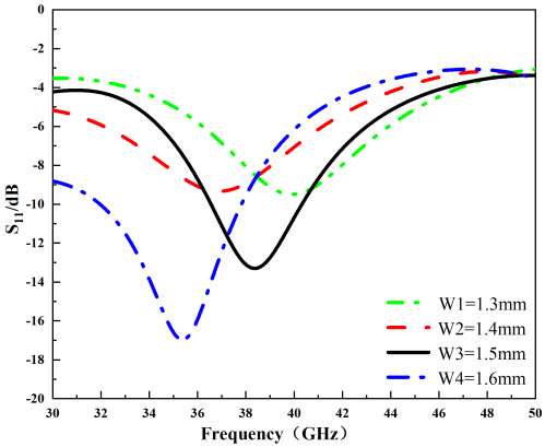
By optimizing the various parameters of the antenna, it is found that the patch and the center feed distance W1 will affect the bandwidth of the antenna. The antenna simulation results are shown in Figure 2. As can be seen from the figure, when W1=1.5mm, the reflection coefficient of the antenna is less than -10dB working bandwidth is 36.54-40.73GHz), fully covering the 5G communication n260 frequency band.
|
|
|
Figure 2. Simulation diagram of\( {S_{11}} \)changing with W1 |
2.2.Binary antenna structure design
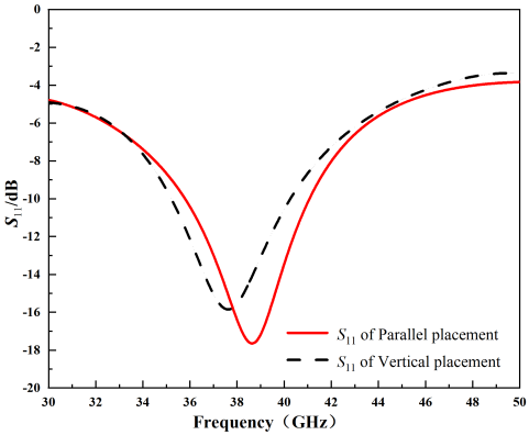
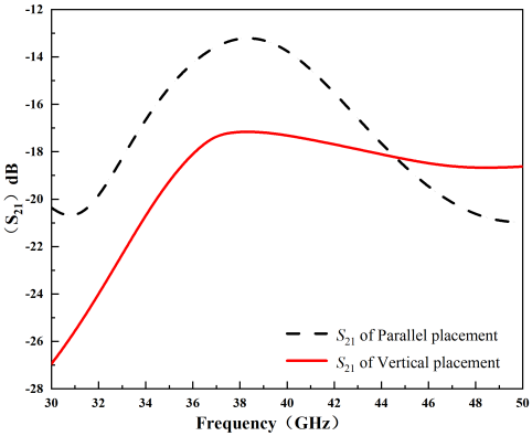
The design idea of the binary MIMO antenna is shown in Figure 3. First, the two antenna units placed in parallel as shown in figure 3 (a), the antenna size is 26mm×5mm×0.508mm, antenna working bandwidth is 35.83-40.23GHz, adjacent isolation is -14dB, the effect can not meet the performance requirements of MIMO antenna, therefore, in order to reduce the isolation, reduce the coupling between the two antennas, the two antennas orthogonally vertical, as shown in Figure 3 (b), the time of the antenna size is 10mm×10mm×0.508mm, the working bandwidth is 35.2-40. 27GHz, isolated at less than -16dB.
|
Figure 3. Structural diagram of the binary antenna MIMO |

The simulation optimization results are shown in Figure 4, although the vertical placement mode makes the working bandwidth of the antenna to change, it can also cover the 5G n260 frequency band range, and improve the antenna isolation degree, which meets the better performance of MIMO antenna.
|
|
|
|
Parallel placement |
Vertical placement |
|
Figure 4. The effect of two different placement modes on the S-parameters |
|
2.3.Design of the quelement antenna structurally
On the basis of the binary MIMO antenna, the antenna array is further expanded to design a four-element MIMO antenna structure. The antenna still adopts the Roogers4352 plate with relative dielectric constant of 3.2 and loss angle tangent of 0.0018, which is consistent with the medium substrate material of the unit antenna. The antenna design idea is shown in Figure 5.
|
Figure 5. Four-element MIMO antenna structure |

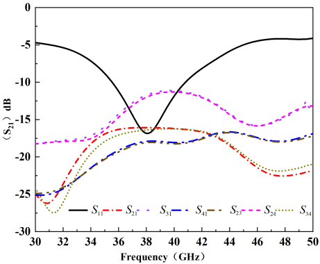
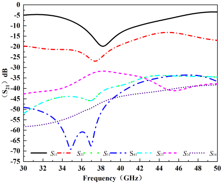
In order to further reduce the interference between antennas and improve the isolation degree, the placement form of the quad antenna is changed. The antenna structure and antenna dimension are shown in Figure 5 (b), and the reference value of the size is shown in Table 1. Figure 6 (b) shows the S parameter of the antenna after orthogonal placement. It can be seen from the figure, the working bandwidth range of the orthogonal imitation antenna is 36.76-41.33GHz. When the antenna still fully covers the n260 frequency band, the isolation degree of each port of the antenna is below-15dB.
|
|
|
||
|
Method 1 |
Method 2 |
||
|
Figure 6. Two kinds of arrangement S-parameters of the quad-element MIMO antenna |
|||
|
Table 1. MIMO antenna size parameter (mm) |
|||
|
L |
10 |
W1 |
0.6 |
|
W |
12 |
W2 |
0.6 |
|
L1 |
1.2 |
W3 |
1.5 |
|
L2 |
3 |
W4 |
0.8 |
3.Analysis of the results of the simulation experiments
3.1.Radiation direction diagram
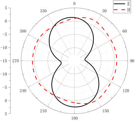
Figure 7 shows the simulation direction diagram of the far-field E and H planes at the central frequency 38.4GHz of the antenna. It can be seen from the figure that the radiation characteristics of the antenna in the n260 frequency band range are good. It can be seen that the E surface is approximately "8" and the H surface is approximately round, indicating that the antenna has certain omnidirectional radiation characteristics.
|
|
|
Figure 7. Radiation direction plot at the central frequency |
3.2.Diversity characterization
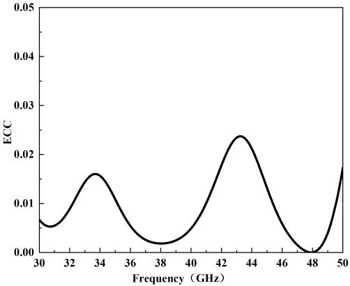
To ensure channel correlation in MIMO communication, we quantified the performance of antenna diversity using the envelope correlation coefficient (ECC) As specified, the MIMO antenna elements must meet the ECC <0.5 criteria to achieve a higher diversity between the MIMO antenna elements.
For the dual-port MIMO antennas, the ECC can be represented by the following formula:
\( ECC=\frac{{|S_{12}^{*}{S_{12}}+S_{21}^{*}{S_{22}}|^{2}}}{(1-{|{S_{11}}|^{2}}-{|{S_{21}}|^{2}})(1-{|{S_{22}}|^{2}}-{|{S_{12}}|^{2}})} \)(1)
Moreover, the ECC value of the antenna is shown in Figure 8, which is less than 0.05 in the working frequency band and meets the standard requirement of less than 0.5.
|
|
|
Figure 8. Simulated results of ECC |
The proposed MIMO antennas are comprehensively compared with several antennas previously reported in Table 2 in terms of size, isolation, operating frequency, and ECC.
Table 2. A slightly more complex table with a narrow caption.
|
Ref. |
Bandwidth(GHz) |
Isolation(dB) |
Size(mm3) |
|
[5] |
24-68.6 |
-19 |
10.1×12 |
|
[6] |
33.7-36.5 |
-40 |
40×40 |
|
[7] |
23.1-35 |
-19 |
13×13 |
|
Proposed |
36.76-41.73 |
-20 |
10×12 |
4.Conclusion
The antenna feeding method designed in this article is a coplanar waveguide method, which has the advantage of smaller size; Based on the traditional unit antenna, an antenna suitable for the n260 frequency band is generated, and then transformed into a binary and quaternary MIMO antenna on this basis, so that its working bandwidth fully covers the 5G n260 frequency band, with a relative bandwidth of 12.7% and a working range of 36.76-41.73GHz. By changing the placement of the quaternary antenna, the isolation degree of each port of the antenna is ultimately below -20dB, and good directionality is maintained, Suitable for the application and expansion of MIMO antennas.
References
[1]. Guo J N, Si Y f, Song R g, and Zu H R 2023 High-Conductivity MXene Film-Based Millimeter Wave Antenna for 5G Applications J. Cryst. 13 L7;
[2]. Elham E, Safieddin S and Serioja T 2019 Design and analysis of a millimetre-wave high gain antenna J. IET Microwaves, Antennas & Propagation. 1586-92;
[3]. QI H H, LI X P ans ZHU H 2021 Low-cost high-order-mode cavity backed slot array antenna using empty substrate integrated waveguide for the 5G n260 band J. Fro. pp 609-614.
[4]. Feng B, Lai J, Chung K L, Chen T Y, Liu Y and Sim C Y 2020 Communication A Compact Wideband Circularly Polarized Magneto-Electric Dipole Antenna Array for 5G Millimeter-Wave Applications J. IEEE. p 68;
[5]. Karamzadeh S, Rafiei V and Kartal M 2020 Beam steering fabry perot array antenna for mm-wave application J. Pro. pp 81-89;
[6]. Wang W X, YAN G Z and Xiong X. Design and development of a miniature low power RF transmitter J. Measurement & Control Technology, 23(1), pp 22-24;
[7]. Chae, S 2007 Analysis of mutual coupling, correlations, and TARC in WiBro MIMO array antenna IEEE. chapter 6, pp 122–125
Cite this article
Nan,J.;Wang,Y.;Zheng,L.;Zhao,L. (2024). A millimeter-wave MIMO antenna applied to the n260 frequency band. Applied and Computational Engineering,52,263-269.
Data availability
The datasets used and/or analyzed during the current study will be available from the authors upon reasonable request.
Disclaimer/Publisher's Note
The statements, opinions and data contained in all publications are solely those of the individual author(s) and contributor(s) and not of EWA Publishing and/or the editor(s). EWA Publishing and/or the editor(s) disclaim responsibility for any injury to people or property resulting from any ideas, methods, instructions or products referred to in the content.
About volume
Volume title: Proceedings of the 4th International Conference on Signal Processing and Machine Learning
© 2024 by the author(s). Licensee EWA Publishing, Oxford, UK. This article is an open access article distributed under the terms and
conditions of the Creative Commons Attribution (CC BY) license. Authors who
publish this series agree to the following terms:
1. Authors retain copyright and grant the series right of first publication with the work simultaneously licensed under a Creative Commons
Attribution License that allows others to share the work with an acknowledgment of the work's authorship and initial publication in this
series.
2. Authors are able to enter into separate, additional contractual arrangements for the non-exclusive distribution of the series's published
version of the work (e.g., post it to an institutional repository or publish it in a book), with an acknowledgment of its initial
publication in this series.
3. Authors are permitted and encouraged to post their work online (e.g., in institutional repositories or on their website) prior to and
during the submission process, as it can lead to productive exchanges, as well as earlier and greater citation of published work (See
Open access policy for details).
References
[1]. Guo J N, Si Y f, Song R g, and Zu H R 2023 High-Conductivity MXene Film-Based Millimeter Wave Antenna for 5G Applications J. Cryst. 13 L7;
[2]. Elham E, Safieddin S and Serioja T 2019 Design and analysis of a millimetre-wave high gain antenna J. IET Microwaves, Antennas & Propagation. 1586-92;
[3]. QI H H, LI X P ans ZHU H 2021 Low-cost high-order-mode cavity backed slot array antenna using empty substrate integrated waveguide for the 5G n260 band J. Fro. pp 609-614.
[4]. Feng B, Lai J, Chung K L, Chen T Y, Liu Y and Sim C Y 2020 Communication A Compact Wideband Circularly Polarized Magneto-Electric Dipole Antenna Array for 5G Millimeter-Wave Applications J. IEEE. p 68;
[5]. Karamzadeh S, Rafiei V and Kartal M 2020 Beam steering fabry perot array antenna for mm-wave application J. Pro. pp 81-89;
[6]. Wang W X, YAN G Z and Xiong X. Design and development of a miniature low power RF transmitter J. Measurement & Control Technology, 23(1), pp 22-24;
[7]. Chae, S 2007 Analysis of mutual coupling, correlations, and TARC in WiBro MIMO array antenna IEEE. chapter 6, pp 122–125