


1. Introduction
With the development of human society and the progress of science and technology, people's travel has become more and more convenient. The aircraft in the whole process plays a very important role. Thanks to the aircraft, people can quickly and arbitrarily reach any destination they would like to go without the limitation of distance and time. Therefore, aircraft have played an irreplaceably important role in the contemporary transportation system. There are different classifications of airplanes, which can be divided into two categories depending on their functions – civilian airplanes and military airplanes. Civilian airplanes make it easier for people's daily lives, which is about traveling through countries and regions and efficient goods-delivery systems. Besides, fighters, early-warning airplanes, jet fighters, and bombers can be recognized as military airplanes, which aim to protect the airspace safety of a country and the integrity of the motherland. Importantly, different from the civilian airplane, the development of military-aimed airplanes is closely related to defence science and technology and national security.[1]
In terms of the structure of airplane, the main difference between a jet fighter and a civil airplane is that the aircraft is defined as a fighter because of its ability to mount weapons, fire control system and to carry both air and ground combat weapons. Secondly, because of its fuselage structure and the special characteristics of the engine, fighter jets can do things that other common aircraft cannot do, which can be illustrated with an example of flying at a speed of more than Mach 1.5 [2]. Besides, to adapt to aerial combat and ground strikes, jet fighters will remove a lot of redundant loading. For example, the pilot's seat is equipped with a rocket ejection device, which turns the comfortable seat for pilots into an escape pod. The ability to provide a huge horsepower of the engine and special structural designs allowed the fighter's fuselage to withstand huge overloads, as well as a certain degree of bullet-proof, waterproof, and fireproof capabilities.
During the latter period of World War II, the United States began to step into the process of the development of new jet fighters. The traditional propeller aircraft in the speed has always been hard, and the height of the aircraft is also a problem [1]. The emergence of jet fighters basically solved the existing problem, The operational principle is that when gas jet nozzles, the jet pushes air backwards, and during the same time the aircraft is pushed forwards by the reverse force. In this way, the stability of the jet fighter can be greatly improved, based on which the speed and mounting capacity are correspondingly enhanced as well.
Early jet fighters - for the second generation and third generation of aircraft, most of the second generation of aircraft were United States of America's F-4 and the Soviet Union MiG series, and most of the third generation in the United States were F-16. YF-16 is the most F-16 prototype. During this development, the fuselage structure of F-16A, F-16B, F-16 block 10, and F-16 block 15 were the following optimized type, which aimed to achieve better aerodynamic effects. The subsequent F-16 block 20 and F-16C/D F-16 block 40/50 were upgraded for radar systems and engine replacements, which purpose was to achieve continuous firepower enhancement and performance upgrades.
This paper analyses in detail the performance of airframe and engine of F-16. Then a comparison of its performance with traditional Soviet fighters of the same period. Specifically, the characteristics and functions of the F-16 have been deeply investigated, which aims to show the superiority of the F-16. Lastly, through this study, the prospects, and personal suggestions for the future development of new jet fighters were stated.
2. F-16 and energy maneuver theory
In the second generation of aircraft, the U.S. Army's F-4 Phantom and the Soviet Union's MiG series of aircraft have been in the dominant stage ref. However, the problem of the U.S. Army's F4 was gradually exposed in the Vietnam battle, which was mainly because the aircraft became extremely heavy when meeting the powerful mounting capacity at the maximum of 15,983 LBS ref. In contrast, this problem did not occur to the MiG and other light fighters. Therefore, in terms of the dogfighting ability, the F4 almost lost its competitivity [3]. In the late 1960s, the U.S. military advocated the official start of the development of the third generation of aircraft [4]. They believed that the determinations of victory in aerial combat were height, speed, firepower, and manoeuvre, which is also known as the most famous energy manoeuvre theory.
Therefore, inspired by the failure of the second generation of ghosts and monsters, the development of the third generation of aircraft began, which adhered to the four major concepts. In January 1972, the U.S. Air Force formally put forward the development of a new fighter aircraft program, the purpose of which was to validate the use of new technologies in the fighter, rather than determine on the development on one specific model. At that time, its main technical requirements were the maximum flight speed of Mach 2, with a lift of 18,000 meters. Under this condition, the fighter could accelerate from Mach 0.9 to Mach 1.5 within one minute at an altitude of 9,000 meters [4]. The other technique developed at the same time is that the aircraft with characteristics of small size, lightweight, and cheap could remain the overload with 3 – 4 G at the speed of Mach 0.9 in the altitude of 12,000 meters, which was a breakthrough at that time [4].
2.1. Motorization, structural characteristics of the airframe
To meet the bidding requirements for the third-generation aircraft, General Electric Company produced the YF-16 prototype in December 1973. After a one-year test, the YF-16 has successfully conducted the first flight test in 1974. After this big success, a series of F-16 aircraft with advanced cross-generation performances formally began their service. This impressive invention broke many traditional restrictions on the fighter, which not only the fire control capacity had been greatly improved, but also the overall shape as well as excellent performance almost behaved the same level as the fourth generation.
The overall weight of F-16 aircraft is 9,295 kg, and its overall length is 15 meters with the length of wing structure of 9.96 meters [5]. To reduce the overall weigh, the component of the structural material of F-16 is 80.6% of traditional aluminium alloy, 7.6% of alloy steel, 2.8% of composite material, 1.5% of titanium alloy and 7.5% of other materials, respectively. Also, 60% of the structural parts inside the aircraft are alloy plates, which can efficiently make the fighter lighter [5].
Besides, to decrease the manufacturing cost, F-16 was designed to minimize the use of special materials. The fuselage adopts a conventional structure consisting of spacer frames and longitudinal beams, with the forward process separation surfaces behind the cockpit and the aft separation surfaces ahead of the drogue. The F-16 adopts a semi-monocoque structure with a short and stubby fuselage profile, which is connected to the wing by the formation of a wing-fuselage. This design effectively makes the fuselage and the wing rounded and smooth, which reduces resistance and improves the ratio of lift-to-resistance. With the rational design, the stiffness is greatly increased, and the fuselage volume is improved by 9%. It is also noticed that the overall weight of the fuselage is reduced by 258 kg, which is also good for reducing the radar reflection area.[6]
2.2. Comparison of F-16 wind tunnel test data and contemporary aircraft
The information of the F-16 has been fully disclosed, so we can use the aerodynamic data of the F-16 aircraft from the low-speed static and dynamic (force oscillations) wind tunnel tests conducted in the wind tunnel facility by Ames and Langley Research Centres in National Aeronautics and Space Administration (NASA) [7].Through the analysis of the data from the wind tunnel tests, it is shown that the aircraft needs leading edge flaps to increase directional stability at large angles of approach, in which way to increase the lift. Therefore, the leading-edge manoeuvring flaps and trailing edge flap ailerons can reach up to 35°/s and change the wing curve degree according to the live aerodynamic requirements. The leading-edge flap improves directional stability and maintains lift at large angles of approach, which reduces jitter. This lifting device allows the F-16 to adopt a small wing with a short wingspan, in which way reduces the weight of 222 kg for the F-16.
Secondly, as shown in the data, the angle of attack and slip angle of F-16 are -20° ≤ a ≤ 90° and -30° ≤ b ≤ 30°, respectively, where the parameter a represents the angle of attack which is the angle between the oncoming airflow and the aircraft when the aircraft makes a significant climb or manoeuvring turn. The parameter b represents the angle of sideslip when the aircraft performs a turn concerning its original track and is divided into a left-slip and a right slip. For a fighter, the larger the angle of attack allows the fighter to obtain better combat advantages. The measured slip angle is one of the important data that can be used to allow pilots to determine the attitude of the aircraft [8]. Compared with the third-generation aircraft developed by the former Soviet Union, taking the MiG 29 and Su-27 as examples, the initial aim to design Su-27 was to counterbalance the heavy fighter, such as F-15, of United States. Therefore, no matter in aerodynamic or in air, the Su27 was uncompetitive. The Su27 has an empty weight of 16,380 kg, and the overall length is 21.9 m with a height of 5.93 m. The wing length is 14.7 m, and the wing area is 62 m2. Compared with the data of F-16, the Su27 with 1.63 ton is almost double, making it no longer a rival to the F-16. Moreover, compared with the wing area of the F-16 (27 m2), its oversized wing area is not capable of good slewing performance in dog fighting.
2.3. Altitude, speed, and engine
In John Boyd theory of energy manoeuvring, the higher the specific excess power (SEP) results in the better performance. SEP refers to the residual power of a fighter, which is also recognized as the stored energy [9]. The entire stored energy is determined by the thrust. So, a good engine is a key to providing a good thrust. Taking the most classic F-16A as an example, its empty weight is 7,230 kg, and the engines used in F-16A are F-100-PW-200, as shown in Fig. 3. The static thrust of F100-PW-200 is shown in Figure 1.
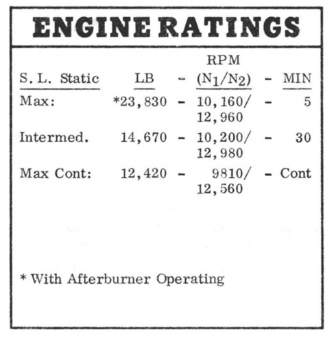
Figure 1. Thrust gravity diagram of the F-16 engine [8].
2.4. Comparison of F-16 engine performance and contemporaneous aircraft
When evaluating the performance of the aircraft, we can use the SEP calculation method to carry out the calculation of different loads in different situations, in which way to optimize the accuracy of the data of the aircraft engine. SEP refers to the energy left in the aircraft in a specific condition of the aircraft, and he is calculated by the equation (1), where T = the thrust of the aircraft, D = the drag force on the aircraft, V = speed, G = weight.
\( SEP=(T-D)*V/G \) (1)
As the data shown that the F100-PW-200 added thrust is about 10,795 kg [10]. According to the climb rate data of the F-16A and the SAC files [11] of the F-16A Blocks 1-10 and F-16A Block 15, the SEP values of the F-16A wingtip carrying two Rattlesnake missiles in 20,880 LBS. of weight for 1G level flight can be calculated. At Mach 0.8 at sea level, the SEP of the F-16A aircraft in this state is 900 ft/s (275 m/s), and at Mach 1 at sea level, the SEP is 600 ft/s (183 m/s) (Figure 2). Besides, when the F100-PW-200 thrust of the F-16 aircraft carries two wingtip AIM-9Js, the drag coefficients are 0.019 and 0.039 at Mach 0.8 and Mach 1, respectively (based on flight test data). Based on the equation D = 0.5 × CD × p × S × V2 together with a reference area of 27.87 m2 and an air density of 1.225 g/m2 at sea level, it can be calculated that the drag for Mach 0.8 and at Mach 1 are 23996 N and 76960 N [10], respectively. According to equation (1), the mass is 20880 LBS equivalent to 9459 kg. Taking SEP and drag into account, the F100-PW-200 thrust can be calculated as 12012 kg and 12944 kg at the speed at Mach 0.8 and Mach 1, respectively. Meantime, the F100 -PW-200 thrust can be estimated as 12,478 kg at Mach 0.9. Besides, the drag coefficient of the F-16 clean configuration at Mach 0.9 is about 0.017[12]. Taking all these parameters into consideration, with the weight of 8,375 kg, the SEP of the F-16A Block 15 fighter at Mach 0.9 at sea level can be estimated at around 355 m/s.
Compared with MiG-29 which were invented at the same period with the air weight of 12,800 kg, by the employment of the same calculation, the maximum added thrust of RD-33 is about 8,300 kg, which is much lower than that of F100-PW-200. At the same time, the SEP of a MiG-29 equipped with two R73 is 325 m/s [13], which is not good as the result mentioned above for F-16 (SEP = 355 m/s), showing the superior performance of F-16 at that time.
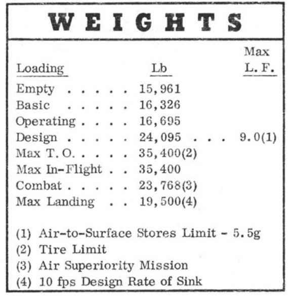
Figure 2. F-16A empty weight [8].
2.5. Firepower, load capacity vs. contemporaneous aircraft
The F-16A has nine weapon mounting points (as shown in Figure 3), and two of them are AIM air-to-air missile mounting points located on the wing tips of the aircraft. The other six weapon mounting points are on the wings which can support a variety of weapon choices, such as AIM-7 air-to-air medium-range radar missile, AIM-9 close-range fighting missile, AIM-120 air-to-air radar missile, AGM-65 air-to-ground missiles, and AGM-88 air-to-ground anti-radiation missiles, AGM-84 air-to-ground anti-ship bombs, AGM-119 anti-ship missiles, etc [14]. In addition, F-16 can also mount the AGM-154 joint outer defence area (JOADA) weapons CBU-87/89/97 cluster bombs, GBU-39 small-diameter bombs, MK-80 series of unguided bombs, pave the way series of guided bombs, joint direct attack (JDAT) bombs, and the B61 nuclear bomb.
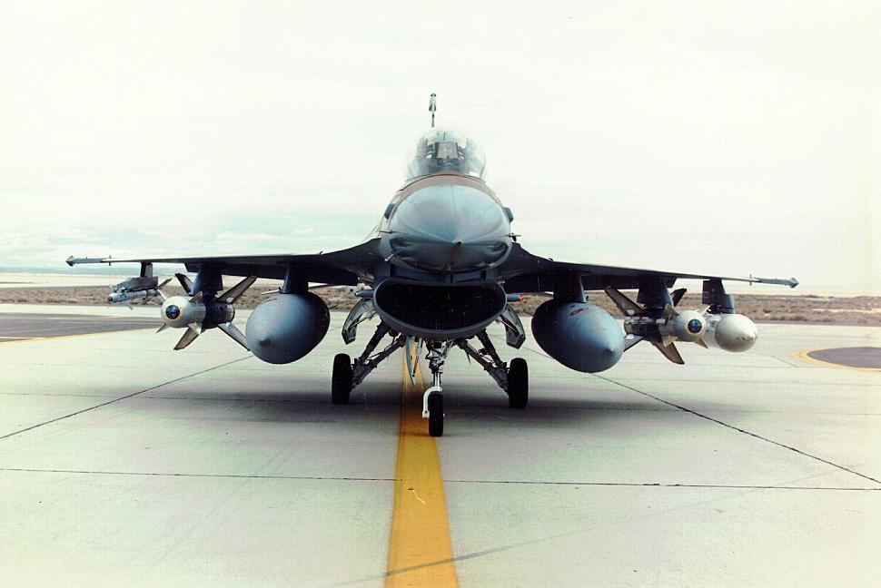
Figure 3. Nine of payload points of F-16.
It is known that the empty weight of F-16 is 15,961 LBS, and its maximum take-off weight is 35,400 LBS. Therefore, taking into account of the weight of the pilots, guns, and 1,000 kg of fuel, the maximum mounting capacity of F-16 is 16,600 LBS based on the 18,800 LBS as the base weight of aircraft. In other words, when the F-16 does not need a secondary fuel tank for long-distance flight, the maximum mounting capacity can reach 16,600 LBS. So, when the F-16 is deployed in a conventional air-to-air armament configuration (two AIM 9l and two AIM 120 with the weight of 190 and 335 LBS, respectively [15, 16]), the conventional air-to-air armament payload is 1050 LBS. It only accounts for 1050 LBS of the maximum take-off weight of 16,600 LBS, which means that the remaining mounting capability of the F-16 is 15550 LBS. When two wing mount points are occupied by two AIM 120, the F-16 will have four weapon drop points remaining, each of which can load 5,000 LBS of mounting capacity. This can be used to mount laser-guided bombs as well as secondary fuel tanks. Compared with the MiG 29 of the same era, which has a maximum take-off weight of 44,000 LBS, and the aircraft has a take-off weight of 33,000 LBS in normal mounting [5]. Through the calculation, mounting capacity of MiG 29 is 11,000 LBS, which is only 66% of that of F-16.
3. Conclusion
In this study, the F-16 fighter has been detailed investigated, which shows that F-16 has obvious advantages over contemporary fighters in aircraft manoeuvrability. Its own lighter body weight and smaller wing area make the F-16 have better rotation performance and air combat advantages. Secondly, the F-16 has the strongest thrust engine of its generation, which contributes to gaining a good SEP value and making the air superiority F-16 of more obvious. Finally, its maximum payload of 16,600 LBS made its ground strike capability significantly superior to that of contemporary fighters. Therefore, through comparative study, the conclusion obtained in this paper can be more conducive to explaining that the development of future fighters should be more inclined to adapt to the multi-role of fighters, rather than giving up other advantages for a specific purpose. In conclusion, the appearance of the F-16 laid the foundation for all advanced fighter aircraft in the future. But until now, the F-16 is still in service in many countries thanks to its excellent performance and practical applications. To sum up, this study provides the comprehensive understanding of the performance of F-16 fighter, which will contribute to the optimization and development of the next generation of fighters in future.
References
[1]. Sekehravani, E. A., Babulak, E., & Masoodi, M. Flying object tracking and classification of. military versus nonmilitary aircraft. Bulletin of Electrical Engineering and Informatics, 2020, 9(4), 1394–1403.
[2]. Ahmed, Amr, Paraskevas, Ioannis, Barbarosou, & Maria. Military aircrafts' classification based. on their sound signature. Aircraft Engineering and Aerospace Technology: An International Journal 2016, 88(1),66–72.
[3]. Pavlovic P. and Pavlovic N. Performance in Practice: Phantom versus MiG-21- How to do split-S in MiG-21 within 3,000ft: Unexploited low speed maneuverability. The Aeronautical Journal, 2010, 114(1155), 339.
[4]. Bongers, Anelí, & Torres, José L. Technological change in U.S. jet fighter aircraft. Research. Policy, 2014, 43(9), 1570–1581.
[5]. USA, Department of Navy. F-16 Flight Manual.
[6]. Triantafyllou T, Nikolaidis T, Diakostefanis M, Pilidis P. Numerical simulation of the airflow over a military aircraft with active intake. Proceedings of the Institution of Mechanical Engineers, Part G. Journal of Aerospace Engineering, 2016, 231(8), 1369–1390.
[7]. Oort E. V., Chu Q. P., Mulder J. A. Robust Model Predictive Control of a Feedback Linearized F-16/MATV Aircraft Model. American Institute of Aeronautics and Astronautics, 2006, 6318.
[8]. Evangelou L., Self A., Allen J., Lo S. Trimmed deep stall on the F-16 Fighting Falcon. The Aeronautical Journal, 2001,105(1054), 679–683.
[9]. Frans P.B. Osinga. Science, Strategy, and War: The Strategic Theory of John Boyd. 2007 ISBN 0–203–08886–7.
[10]. Camm, Frank, and T. K. G. Jr. The Development of the F100-PW-220 and F110-GE-100 Engines: Case Study of Risk Assessment and Risk Management. 1993. 1–91
[11]. F-16A block 15 falcon SAC - March 1984 Scribd.
[12]. Porcher, C. E. The F-16 Common Engine Bay. ASME International Gas Turbine Conference & Exhibit, 1985, 1–8.
[13]. Russia, Air Force Department, Mig29 pilot textbook.
[14]. Fan Hui Tao, Cui Hao, and Tian Guang. Overview of air-to-air Missile Development in 70 Years. Aviation Weapons, 2016, 10(1), 4–12
[15]. AIM-120 AMRAAM (no date) Air Force. Available at: https://www.af.mil/About-Us/Fact Sheets/Display/Article/104576/aim-120-Amram/ (Accessed: 25 August 2023).
[16]. AIM-9 Sidewinder (no date) Air Force. Available at: https://www.af.mil/About-Us/Fact Sheets/Display/Article/104557/aim-9-sidewinder/ (Accessed: 25 August 2023).
Cite this article
Zhaxi,Z. (2024). Research on airframe structure, engine performance, weapon mounting capability of F-16. Applied and Computational Engineering,56,265-271.
Data availability
The datasets used and/or analyzed during the current study will be available from the authors upon reasonable request.
Disclaimer/Publisher's Note
The statements, opinions and data contained in all publications are solely those of the individual author(s) and contributor(s) and not of EWA Publishing and/or the editor(s). EWA Publishing and/or the editor(s) disclaim responsibility for any injury to people or property resulting from any ideas, methods, instructions or products referred to in the content.
About volume
Volume title: Proceedings of the 4th International Conference on Materials Chemistry and Environmental Engineering
© 2024 by the author(s). Licensee EWA Publishing, Oxford, UK. This article is an open access article distributed under the terms and
conditions of the Creative Commons Attribution (CC BY) license. Authors who
publish this series agree to the following terms:
1. Authors retain copyright and grant the series right of first publication with the work simultaneously licensed under a Creative Commons
Attribution License that allows others to share the work with an acknowledgment of the work's authorship and initial publication in this
series.
2. Authors are able to enter into separate, additional contractual arrangements for the non-exclusive distribution of the series's published
version of the work (e.g., post it to an institutional repository or publish it in a book), with an acknowledgment of its initial
publication in this series.
3. Authors are permitted and encouraged to post their work online (e.g., in institutional repositories or on their website) prior to and
during the submission process, as it can lead to productive exchanges, as well as earlier and greater citation of published work (See
Open access policy for details).
References
[1]. Sekehravani, E. A., Babulak, E., & Masoodi, M. Flying object tracking and classification of. military versus nonmilitary aircraft. Bulletin of Electrical Engineering and Informatics, 2020, 9(4), 1394–1403.
[2]. Ahmed, Amr, Paraskevas, Ioannis, Barbarosou, & Maria. Military aircrafts' classification based. on their sound signature. Aircraft Engineering and Aerospace Technology: An International Journal 2016, 88(1),66–72.
[3]. Pavlovic P. and Pavlovic N. Performance in Practice: Phantom versus MiG-21- How to do split-S in MiG-21 within 3,000ft: Unexploited low speed maneuverability. The Aeronautical Journal, 2010, 114(1155), 339.
[4]. Bongers, Anelí, & Torres, José L. Technological change in U.S. jet fighter aircraft. Research. Policy, 2014, 43(9), 1570–1581.
[5]. USA, Department of Navy. F-16 Flight Manual.
[6]. Triantafyllou T, Nikolaidis T, Diakostefanis M, Pilidis P. Numerical simulation of the airflow over a military aircraft with active intake. Proceedings of the Institution of Mechanical Engineers, Part G. Journal of Aerospace Engineering, 2016, 231(8), 1369–1390.
[7]. Oort E. V., Chu Q. P., Mulder J. A. Robust Model Predictive Control of a Feedback Linearized F-16/MATV Aircraft Model. American Institute of Aeronautics and Astronautics, 2006, 6318.
[8]. Evangelou L., Self A., Allen J., Lo S. Trimmed deep stall on the F-16 Fighting Falcon. The Aeronautical Journal, 2001,105(1054), 679–683.
[9]. Frans P.B. Osinga. Science, Strategy, and War: The Strategic Theory of John Boyd. 2007 ISBN 0–203–08886–7.
[10]. Camm, Frank, and T. K. G. Jr. The Development of the F100-PW-220 and F110-GE-100 Engines: Case Study of Risk Assessment and Risk Management. 1993. 1–91
[11]. F-16A block 15 falcon SAC - March 1984 Scribd.
[12]. Porcher, C. E. The F-16 Common Engine Bay. ASME International Gas Turbine Conference & Exhibit, 1985, 1–8.
[13]. Russia, Air Force Department, Mig29 pilot textbook.
[14]. Fan Hui Tao, Cui Hao, and Tian Guang. Overview of air-to-air Missile Development in 70 Years. Aviation Weapons, 2016, 10(1), 4–12
[15]. AIM-120 AMRAAM (no date) Air Force. Available at: https://www.af.mil/About-Us/Fact Sheets/Display/Article/104576/aim-120-Amram/ (Accessed: 25 August 2023).
[16]. AIM-9 Sidewinder (no date) Air Force. Available at: https://www.af.mil/About-Us/Fact Sheets/Display/Article/104557/aim-9-sidewinder/ (Accessed: 25 August 2023).