


1. Introduction
Following the European energy crisis, countries worldwide have focused on the development and application of clean energy sources, such as solar energy [1]. In the research of solar energy application technology, increasing solar energy utilization efficiency has become a new focus. Besides researching new types of solar photovoltaic panels [2], improving the reception efficiency of solar radiation by solar photovoltaic panels is also an important direction [3, 4]. Depending on the number of rotation axes, solar tracking can be divided into single-axis and dual-axis tracking. Due to limited upgrade space for single-axis tracking technology and lower photoelectric conversion efficiency compared to dual-axis tracking [5-7], the primary research direction both domestically and internationally is dual-axis tracking [8].
To date, there are many automated dual-axis solar trackers that work based on various algorithms. The current mainstream solar tracking control algorithms include photoelectric tracking and sun path trajectory tracking [9]. Photoelectric tracking relies on photoelectric sensor components to generate feedback signals to the processor based on the intensity variation of sunlight incident on the solar panel. The processor then runs a program to adjust the angle of the solar photovoltaic panel for tracking. This method belongs to closed-loop real-time tracking and can track the sun's movement at any time [10]. However, it has limitations, such as inability to track during overcast or low-light conditions, lower accuracy in light [11], and the high cost of high-precision light sensors. Sun path trajectory tracking is based on the trajectory of the sun and the Earth's movement, using the equatorial coordinate system or the horizontal coordinate system to describe the sun's orientation relative to the Earth [12]. However, the sun's trajectory is highly influenced by seasonal and time changes, leading to accumulated errors in device operation that cannot be eliminated, requiring precise geographic location and accurate time sources [13]. The use of the BeiDou Satellite Navigation System (BDS) can offer higher accuracy and security than GPS in the Asia-Pacific region [14].
Existing tracking devices have limited consideration for environmental factors such as weather, and those that do consider weather factors often use a large number of sensors for weather condition detection [15]. This approach is costly and imposes significant limitations on detection accuracy and coverage. To address these issues, this device utilizes a control scheme that combines sun path tracking with photoelectric tracking. It uses Internet of Things (IoT) technology to acquire real-time weather data from the internet and predict future weather conditions. This approach not only enhances detection accuracy and coverage but also provides the device with the ability to sense extreme weather conditions. The foldable design facilitates transportation and equips the device to handle extreme weather conditions. During operation, the device uploads critical parameters to a server, which monitors device operation and issues alarms in case of anomalies, thereby reducing the cost of manual inspections and regular maintenance when the device is deployed on a large scale.
2. Device Overall Design
This device controls the mechanical structure through a control unit. The control unit communicates with a server via an IoT module, obtaining critical information and transmitting device operating parameters. Operators can access relevant parameters of the device's operation and control it through a PC or a mobile terminal. The process is illustrated in Figure 1.
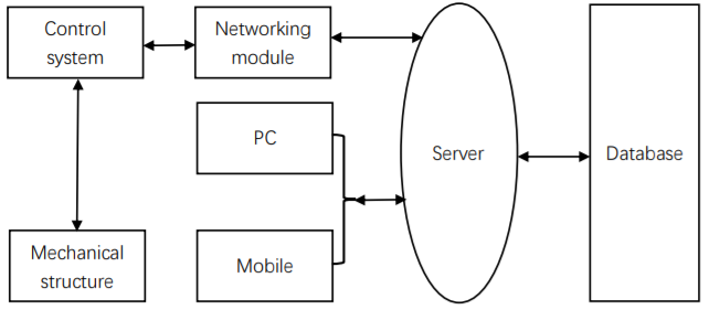
Figure 1. Overall Workflow.
2.1. Device Structure Design
This device consists of a solar panel folding structure, a dual-axis rotation structure, and an automatic cleaning structure. The overall design model is shown in Figure 2. The device uses a dual-axis rotation mechanism to control the pitch and azimuth angles of the device. It utilizes a folding mechanism to automatically retract the solar photovoltaic panel and a cleaning mechanism to remove debris accumulated on the solar panel.
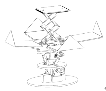
Figure 2. Overall Design
2.1.1. Folding Structure Design. The folding structure is used to automatically retract the photovoltaic panel to protect it from external factors. It covers the photovoltaic panel with an enclosure to shield it from such influences. This mechanism uses an electric motor to change the direction of power transmission by reversing the gear, which controls the rack engaged with the gear to move up and down along a slide rail. This, in turn, moves the frame with the photovoltaic panel, extending the device's lifespan and increasing the utility of the photovoltaic panel. The structure is schematically shown in Figure 3 and a simplified structure diagram in Figure 4.
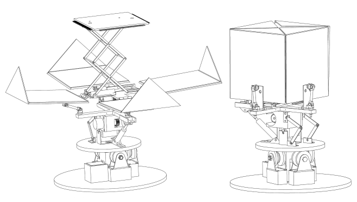
Figure 3. Schematic of Folding State
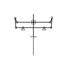
Figure 4. Schematic of the Rod Structure.
The long and short rods of the solar panel opening and closing mechanism primarily endure bending stress during operation, resulting in elastic deformation. The rods of the solar panel opening and closing mechanism are all made of 9000r resin material, seamless cylindrical shape with a diameter of Φ6. It has been verified that the allowable bending stress for this material is in the range of 70-140 MPa. Based on the force conditions of the solar panel opening and closing mechanism's rods (considering the weight of the panels and support rods), their maximum stress angle is treated as that of a cantilever beam.
\( Cylindrical section factor:\frac{{I_{c}}}{A}=\frac{64}{{d^{2}}}\ \ \ (1) \)
\( {Maximum bending stress: σ_{max}}=\frac{{M_{max}}}{W}\ \ \ (2) \)
Using the principle of conservation, the maximum bending stress experienced by the long rod of the solar panel opening and closing mechanism is calculated to be 7.734375×10³ Pa. Mechanical simulations have shown that the maximum bending stress is 5.878×10³ Pa, which is significantly lower than the minimum allowable bending stress of 70 MPa. Therefore, it can be concluded that both the structure and the materials are sufficient to meet the requirements of the solar panel opening and closing.
2.1.2. Cleaning Structure Design. The cleaning structure lifts a flat surface equipped with brushes to clean debris on the inner side of the solar panel. To achieve this, a pure shear mechanism is used for lifting the flat surface. An air cylinder provides the power for the shear mechanism to move up and down along the Z-axis, as shown in Figure 5. The air cylinder is horizontally fixed on the flat surface of the shear mechanism, and the shear mechanism's main shaft is fixed to the air cylinder. The air cylinder provides thrust to move the cleaning surface along the Z-axis. This approach using the air cylinder push rod in the shear mechanism provides the device with functionality, compact size, higher power, and smoother device movement without sudden speed increases, as well as a greater stroke.
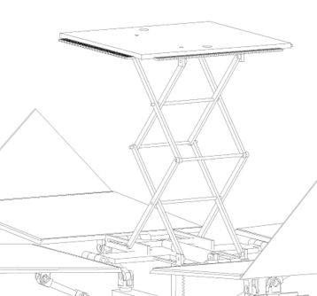
Figure 5. Shear Lifting Mechanism.
2.1.3. Dual-Axis Rotation Structure Design. The dual-axis rotation mechanism consists of pitch adjustment mechanism (Figure 6) and azimuth adjustment mechanism (Figure 7).
The pitch adjustment mechanism is powered by a servo motor that controls the opening and closing mechanism connected to the top to achieve high-angle solar tracking. To prevent the device from dropping in case of a power failure and potentially damaging the photovoltaic panel or exceeding specified limits of displacement, damping rods and limiting connecting rods are added to the pitch mechanism connection seat. The limiting connecting rod stops the movement when the device reaches the limit position. After a power failure, the pneumatic damper controls the movement of the cross bracket, increasing safety.
To ensure smooth and precise control of the device's azimuth angle, the azimuth adjustment mechanism uses a stepper motor to drive the worm for power to control the device's azimuth angle. The worm is fixed to the main rotation shaft, which is only coupled at the bottom and top with the main shaft. To stabilize the device when changing azimuth angles, three fixed wheels are added to the bottom of the azimuth adjustment mechanism to secure the upper plane, ensuring stability during changes in device azimuth angle.
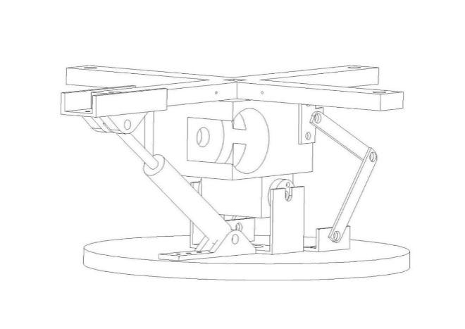
Figure 6. Pitch Adjustment Structure.
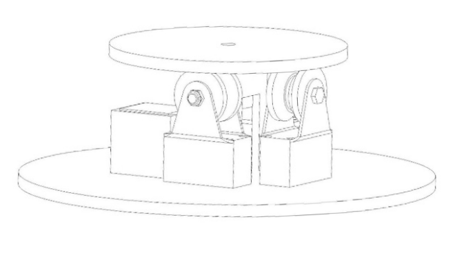
Figure 7. Azimuth Adjustment Structure.
2.2. Control System and Software Design
2.2.1. Control Circuit Section. The hardware circuit of this device is centered around the STM32F103C8T6 microcontroller. It communicates with the ATGM336H satellite positioning module to calculate the solar zenith angle. The microcontroller collects data from light-sensitive sensors via the RS485 bus and then uploads the processed data to a cloud platform's database using the ESP8266 communication module. The cloud platform further analyzes and processes the data and sends instructions to the control unit through the ESP8266 communication module to execute operations. The control system can be remotely controlled through an IoT cloud platform.
2.2.2. User Software Design. The user software is primarily deployed on a cloud-based monitoring platform. Management and maintenance personnel can access this platform through a web browser to monitor and control the device's operation. The cloud platform monitoring page uses a mature HTML+CSS+JavaScript solution and is also compatible with mobile devices, providing dynamic interaction and information display capabilities for different device models. Data visualization techniques have been introduced to display the data obtained from the server in a more intuitive way. The page resources are loaded using the popular CDN technology to reduce server access pressure, accelerate resource loading, and improve concurrent access.
On the server side, features like SMS alerts and permission granting and authentication have been configured. Management and maintenance personnel need to log in with their accounts, and the server grants an encrypted token after successful verification. The token is checked each time an operation is performed to ensure data and operation security. In case of device disconnection, management and maintenance personnel are notified via SMS, enhancing the automation of the device and making the entire process more intelligent.
Device operating data is stored in a relational database, divided into device information (ID, device number) and detailed device data information (ID, device latitude and longitude, local weather, device operating status). Device information and detailed information are linked through the primary key ID, and by partitioning the tables, database access pressure is reduced, achieving on-demand loading. When configuring the database, optimizations have been made for statements with lower execution efficiency, enhancing query speed.
2.3. Control Flow
The control flow of this device is depicted in Figure 8. After program initialization, the main control board waits for the connection of the ATGM336H satellite positioning module with the BeiDou Satellite Navigation System. Once the BDS connection is successful, real-time data such as time and latitude and longitude are sent to the satellite positioning module. The main control board calculates the angles that the device's high position and azimuth need to rotate based on the data received from the satellite positioning module. Simultaneously, it uses IoT technology to monitor the weather conditions in real-time and converts the weather conditions into data, which is then sent to the main control board via the WIFI module. When the weather is suitable, the main control board deploys the device and rotates the stepper motor and digital servo motor to the calculated angles.
Next, the main control board processes the values detected by the four light-sensitive sensor modules and compares them pairwise. If there is a significant deviation, it controls the relevant motors or servo motors to reduce the error. This loop enables the device to maintain the highest photoelectric conversion rate in real-time.
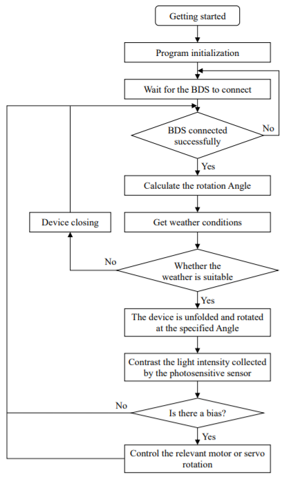
Figure 8. Software Flowchart of the Control Section.
3. Experimental Results and Discussion
Figure 9 presents a comparison of the power generation between this device and a fixed solar power generation system. These experimental data were collected from May 30, 2023, starting at 6:30 AM and continuing until 5:30 PM. At the beginning of the experiment, the weather was clear and sunny until 1:00 PM. During this period, both systems showed a continuous increase in power generation, with this device significantly outperforming the fixed system in power generation. However, at 1:30 PM, the weather began to change, becoming overcast, and the energy generated by both systems virtually ceased to increase. Rain started around 3:00 PM, causing a decline in the power generation of the solar panels. Between 3:30 PM and 4:30 PM, thick clouds covered the sun, and the energy output of both systems became almost identical, but this device still managed to generate more energy.
Multiple comparative experiments were conducted, and the data collected were summarized. By comparing the power generation at the same time periods throughout the day for both systems, the conclusion can be drawn that this device's power generation is 34.8% higher than that of the fixed solar power generation system.
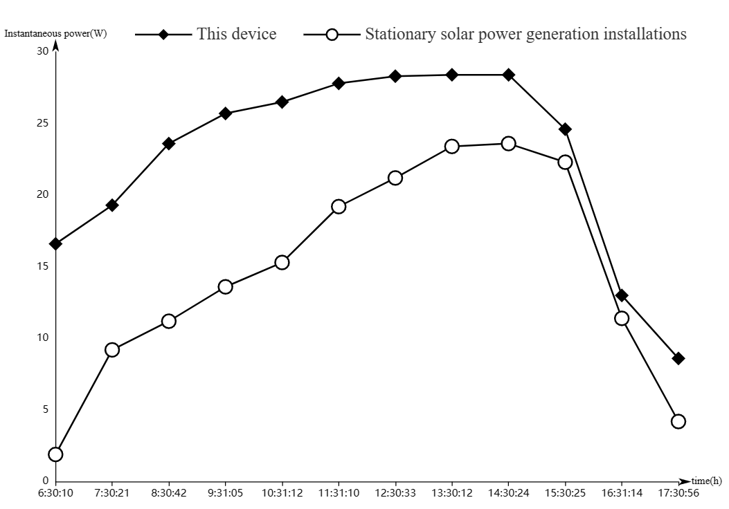
Figure 9. Comparative Test Results of Power Generation between this Device and Fixed Solar Power Generation System
4. Conclusion
This project has developed an environmentally robust solar tracking system based on IoT and BDS technology. It combines solar tracking methods, including solar day tracking and photoelectric tracking, and optimizes the overall solution. It utilizes the BeiDou Satellite Navigation System (BDS) for precise positioning and employs the STM32 microcontroller as the main control unit, forming a complete control system. A cloud-based monitoring platform has been developed, integrated with IoT technology and ESP8266 modules, enabling real-time monitoring of both weather conditions and the device.
Through multiple comparative experiments, experimental data revealed that this device achieved a 34.8% increase in power generation compared to a fixed solar power generation system. The combination of various control strategies maximizes the utilization of solar energy resources. Additionally, the introduction of weather variables and the design of a self-cleaning structure have endowed the device with the capability to withstand adverse weather conditions.
This device can be applied to the construction of photovoltaic stations in challenging environments like deserts and serve as a power source for public lighting systems. It is also suitable for rooftop photovoltaic power generation in urban and rural areas, as well as decentralized power generation in rural communities.
Acknowledgments
This work has received financial support from the China National Undergraduate Innovation and Entrepreneurship Training Program (Project No. 202210356020). We would like to express our gratitude for this support.
References
[1]. Cruz-Peragón, F., Casanova-Peláez, P. J., Díaz, F. A., et al. (2011). An approach to evaluate the energy advantage of two axes solar tracking systems in Spain. *Applied Energy, 88*(12), 5131-5142.
[2]. Ou, J., Bao, P., Yin, H., et al. (2020). Research and analysis of automatic solar panel tracking devices. *Journal of Agricultural Equipment and Vehicle Engineering, 58*(12), 15-18.
[3]. Liu, X. (2019). Design of a fully automatic dual-axis solar power generation vehicle. *China New Technology and New Product, 2019*(13), 2.
[4]. Zhe, L. W., Irwan, Y. M., Irwanto, M., et al. (2016). Temperature Distribution of Three-Dimensional Photovoltaic Panel by Using Finite Element Simulation.
[5]. Zhao, Y. (2019). Design of a solar dual-axis tracking system based on STC89 C52 microcontroller. *Shanxi Electronic Technology, 2019*(6), 4.
[6]. Peng, Z., Li, H., Yang, W., et al. (2015). Design and implementation of a two-degree-of-freedom solar tracking control system. *Instrumentation Technology, 2015*(10), 4.
[7]. Ren, W., & Song, T. (2010). Development of a dual-axis photovoltaic cell automatic tracking system. *Sensor World, 16*(05), 22-23+10.
[8]. Liu, L. X. (Dissertation). (Year). Design and implementation of a solar sun-tracking system based on MCU. *Hebei Normal University of Science and Technology*.
[9]. Qu, M. (2015). Development of a solar automatic tracking system based on DSP. *Automation Application, 2015*(6), 3.
[10]. Yao, Z., Pan, F., & Tan, D. Y. (2016). Design of a new type of intelligent sun-tracking system for photovoltaic power generation. *Journal of Solar Energy, 37*(5), 6.
[11]. Ahammed, F. R., Asif, M. M., Sanzidur, R., et al. (2014). Energy Efficient Hybrid Dual Axis Solar Tracking System. *Journal of Renewable Energy, 2014*, 112.
[12]. Dong, C., Zhang, Y., Gao, S., et al. (2022). Design of a sun-tracking system based on solar movement trajectory tracking. *Electronic Testing, 2022*(11), 31-33, 27.
[13]. Feng, Y., Wang, L. Q., Wang, X. T., et al. (2022). Dual-axis trajectory automatic solar tracking system based on GPS positioning algorithm. *Instrumentation Users, 2022, 29*(1), 4.
[14]. Dai, Z. J., Xu, Y. F., Su, Q. Q., et al. (2014). Solar tracking system based on BeiDou timing and positioning. *Journal of Shanghai University of Electric Power, 2014, 17*(3), 7.
[15]. Zhao, H. T., & Wu, W. K. (2018). Design of a foldable solar automatic tracking photovoltaic power generation device. *Automation Technology and Applications, 2018, 37*(9), 136-139.
Cite this article
Wang,Q.;Jia,H.;Hu,H.;Lu,P.;Zhao,B.;Yang,G. (2024). Solar photovoltaic automatic tracking device based on IoT and BDS. Applied and Computational Engineering,59,184-191.
Data availability
The datasets used and/or analyzed during the current study will be available from the authors upon reasonable request.
Disclaimer/Publisher's Note
The statements, opinions and data contained in all publications are solely those of the individual author(s) and contributor(s) and not of EWA Publishing and/or the editor(s). EWA Publishing and/or the editor(s) disclaim responsibility for any injury to people or property resulting from any ideas, methods, instructions or products referred to in the content.
About volume
Volume title: Proceedings of the 4th International Conference on Materials Chemistry and Environmental Engineering
© 2024 by the author(s). Licensee EWA Publishing, Oxford, UK. This article is an open access article distributed under the terms and
conditions of the Creative Commons Attribution (CC BY) license. Authors who
publish this series agree to the following terms:
1. Authors retain copyright and grant the series right of first publication with the work simultaneously licensed under a Creative Commons
Attribution License that allows others to share the work with an acknowledgment of the work's authorship and initial publication in this
series.
2. Authors are able to enter into separate, additional contractual arrangements for the non-exclusive distribution of the series's published
version of the work (e.g., post it to an institutional repository or publish it in a book), with an acknowledgment of its initial
publication in this series.
3. Authors are permitted and encouraged to post their work online (e.g., in institutional repositories or on their website) prior to and
during the submission process, as it can lead to productive exchanges, as well as earlier and greater citation of published work (See
Open access policy for details).
References
[1]. Cruz-Peragón, F., Casanova-Peláez, P. J., Díaz, F. A., et al. (2011). An approach to evaluate the energy advantage of two axes solar tracking systems in Spain. *Applied Energy, 88*(12), 5131-5142.
[2]. Ou, J., Bao, P., Yin, H., et al. (2020). Research and analysis of automatic solar panel tracking devices. *Journal of Agricultural Equipment and Vehicle Engineering, 58*(12), 15-18.
[3]. Liu, X. (2019). Design of a fully automatic dual-axis solar power generation vehicle. *China New Technology and New Product, 2019*(13), 2.
[4]. Zhe, L. W., Irwan, Y. M., Irwanto, M., et al. (2016). Temperature Distribution of Three-Dimensional Photovoltaic Panel by Using Finite Element Simulation.
[5]. Zhao, Y. (2019). Design of a solar dual-axis tracking system based on STC89 C52 microcontroller. *Shanxi Electronic Technology, 2019*(6), 4.
[6]. Peng, Z., Li, H., Yang, W., et al. (2015). Design and implementation of a two-degree-of-freedom solar tracking control system. *Instrumentation Technology, 2015*(10), 4.
[7]. Ren, W., & Song, T. (2010). Development of a dual-axis photovoltaic cell automatic tracking system. *Sensor World, 16*(05), 22-23+10.
[8]. Liu, L. X. (Dissertation). (Year). Design and implementation of a solar sun-tracking system based on MCU. *Hebei Normal University of Science and Technology*.
[9]. Qu, M. (2015). Development of a solar automatic tracking system based on DSP. *Automation Application, 2015*(6), 3.
[10]. Yao, Z., Pan, F., & Tan, D. Y. (2016). Design of a new type of intelligent sun-tracking system for photovoltaic power generation. *Journal of Solar Energy, 37*(5), 6.
[11]. Ahammed, F. R., Asif, M. M., Sanzidur, R., et al. (2014). Energy Efficient Hybrid Dual Axis Solar Tracking System. *Journal of Renewable Energy, 2014*, 112.
[12]. Dong, C., Zhang, Y., Gao, S., et al. (2022). Design of a sun-tracking system based on solar movement trajectory tracking. *Electronic Testing, 2022*(11), 31-33, 27.
[13]. Feng, Y., Wang, L. Q., Wang, X. T., et al. (2022). Dual-axis trajectory automatic solar tracking system based on GPS positioning algorithm. *Instrumentation Users, 2022, 29*(1), 4.
[14]. Dai, Z. J., Xu, Y. F., Su, Q. Q., et al. (2014). Solar tracking system based on BeiDou timing and positioning. *Journal of Shanghai University of Electric Power, 2014, 17*(3), 7.
[15]. Zhao, H. T., & Wu, W. K. (2018). Design of a foldable solar automatic tracking photovoltaic power generation device. *Automation Technology and Applications, 2018, 37*(9), 136-139.