


1. Introduction
Bridges have been playing a pivotal role in transportation for an extended period. Since the 21st century, with the development of new materials and construction technology, many countries have planned to build super-span bridges. However, the larger the spans of bridges are, the softer the stability problem caused by wind load will be severe [1]. The earliest case of instability of a bridge under wind load appeared in 1879 when a 3.2 km single-track railway bridge (Tay Bridge) on the River Tay in Scotland suddenly failed under wind load. In this accident, a 7-car train fell into the river with the middle part of the bridge, resulting in 75 deaths. In 1967, Hirai found the phenomenon of static instability in the wind tunnel test of the whole bridge aeroelastic model [2]. In 1997, Tongji University also found the above phenomenon when doing the entire bridge aeroelastic model wind tunnel test on the Shantou Haiwan Second Bridge. The occurrence of this phenomenon sends a warning signal to the aerostatic stability of future super-large-span cable-loaded bridge structural systems [3]. Frangopol considered the effect of structural geometric nonlinearities on the strength of large-span suspension bridges and evaluated the stability of large-span suspension bridges in Japan [4]. Liang conducted a static wind stability analysis of suspension bridges [5], and Chen focused on the stability theory and its calculation method with the background of large-span cable-stayed bridges and considered the effects of the initial wind angle of attack, the presence or absence of a center-buckled wind-resistant cable-stayed structure, and other factors [6]. All these scholars used deterministic analysis methods to analyze the static wind stability of bridges [7][8]. The existing software used to calculate the static wind instability of large-span suspension bridges is more complicated to operate, the popularity of the software is not high, and the period analysis method is not perfect. It is necessary to summarize and compile a set of analysis procedures that can be applied to the existing general finite element calculation software, simplify the parameter input of which the calculation is in the design, and quickly be used and promoted in the bridge design.
This paper summarizes previous research results based on static wind stability of suspension bridges, and the corresponding fundamental theories are introduced in detail. The related analysis program is prepared using the ANSYS APDL language.
2. Static wind instability analysis theory of long-span suspension bridge
2.1. Static wind loads
The long-span suspension bridge mainly comprises the main beam, bridge tower, cable, and derrick. In the general calculation, the wind load on the central building, main line, and boom only considers the action of resistance [9]. The static wind action of the main beam is decomposed into three components, namely, drag force, lift force, and lifting moment, which are derived from the hydrodynamics of aircraft wings [10]. In the research, the natural wind is generally divided into the average air volume that does not change with time and the pulsating air volume that changes with time. The superposition of the effect of these two parts is the turbulent flow that considers the pulsating development of natural wind. The force of the wind on the structure that does not change with time is called the static force, and the parameter describing the static wind effect is called the static three-component force coefficient of the main beam. The static tripartite force is established in the wind coordinate system, as shown in Figure 1. The static three-component force coefficientas shown in Eq.1; Eq.2 and Eq.3.
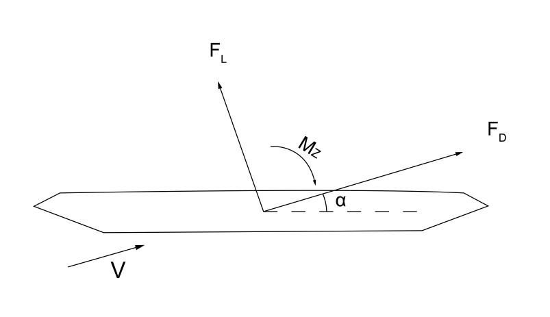
Figure 1. Static tripartite force in wind axis coordinates
Drag coefficient:
\( {C_{D}}=\frac{{F_{D}}}{0.5ρ{U^{2}}D}\ \ \ (1) \)
Lift coefficient:
\( {C_{L}}=\frac{{F_{L}}}{0.5ρ{U^{2}}B}\ \ \ (2) \)
Torque coefficient:
\( {C_{M}}=\frac{{M_{z}}}{0.5ρ{U^{2}}{B^{2}}}\ \ \ (3) \)
FD, FL, and Mz are the force force under the condition of unit length, and FD is the bridge resistance (N). FL is section lift (N); MT is the torque of the bridge section (N·m); \( ρ \) is the density of air (kg/m3); D is the height of the bridge section (m); B is the width of the bridge section (m); U is the incoming wind speed (m/s).
2.2. Stability Analysis Theory
As a classical problem in structural mechanics, it can be concluded from many engineering accidents that studies based on stability problems need to be emphasized. In bridge engineering, the stability problem also exists. Suspension bridges have light structure and low stiffness, so the stability problem is most apparent [10]. When the external load applied to the network increases to a specific value, the system will transition from equilibrium to non-equilibrium. If its interference causes external complex factors, the degree of structural deformation will be rapidly deepened, ultimately resulting in a substantial reduction in the structural load-bearing capacity of the structure; this phenomenon is also known as the structural instability phenomenon. The stability of the bridge structure is essential and needs to be maintained in all directions at all times. Usually, experts use stability theory to analyze its strength. Stability theory can be divided into branch point instability and extreme point instability according to the specific state of structural flux.
2.2.1. Type I stability issues. Type I stability issues are the eigenvalue problem: when the structure is subjected to a certain degree of external load, there are two equilibrium states, where the critical value of the two equilibrium states is the compression curvature load, and then this kind of instability phenomenon is also called branch point instability. Therefore, when using the finite element analysis method to deal with it, it can be converted into a generalized eigenvalue solution [10]. As Eq.4.
\( |([{K_{0}}]+λ[{K_{σ}}])|=0\ \ \ (4) \)
Where [ \( {K_{0}} \) ] is the geometric stiffness matrix under reference load; [ \( {K_{σ}} \) ] is the linear elastic stiffness matrix. The eigenequation theoretically has n eigenvalues \( {λ_{1}},{λ_{2}} \) ,..., \( {λ_{n}} \) . For many engineering stability problems, the minimum eigenvalue is of real engineering significance, generally called the stability coefficient. Therefore, when solving the type I stability issue, it is usually necessary to convert it into the minimum eigenvalue of the solution equation.
Type I stability issues are often based on the ideal state. However, in the large-span bridge structure, the members' force and the system's stress state are usually more complex than the theoretical situation. In addition, many complex nonlinear factors in the project will interfere with the stability analysis of the structure to a certain extent, while the type I stability issue is not considered. The style I stability issue is theoretically assumed to have sufficient bearing capacity before component instability; however, in practice, the application of structural loads is inconsistent. Also, if the actual structural behavior has a significant difference, then the type I stability issue has certain limitations. Therefore, most engineering structural stability problems are generally type II stability issues.
2.2.2. Type II stability issues. Type II stability is the pole-point instability problem, where the structure is subjected to an applied load and always remains in an equilibrium state. However, the shipment applied to the system reaches a certain level. In that case, even if the load is stopped, the structure will be deformed rapidly, the deformation will continue to increase, and the system will eventually be damaged. However, if the load applied to the network reaches a certain level, the structure will rapidly deform even if the bag is unused. The deformation will continue to increase, and eventually, the system will be damaged. In addition, the corresponding critical load is the ultimate load of the structure, and this kind of structural instability is also called extreme point instability.
Many stability issues that arise in practical engineering are essentially Type II stability issues. The concept of ultimate load derived from this type of stability issue has led to the birth of the maximum load state design method. The idea of ultimate loads derived from such stability problems led to the birth of the top load state design method, which utilizes the structural strength reserve of the traditional design method to the fullest. This method makes full use of the structural strength reserve of the conventional design method.
In solving finite element ultimate loads, it is often necessary to carry out an entire process analysis [11]. In addition, when using elastic-plastic finite displacement theory, it is essential to focus on the material and geometric nonlinear influences and approximate the ultimate load through the equilibrium equations. As shown in Eq.5.
\( [K(\lbrace δ\rbrace )]\cdot \lbrace δ\rbrace =\lbrace P\rbrace \ \ \ (5) \)
Where [K({ \( δ \) })] is the global stiffness of the structure;{ \( δ \) }is the displacement vector; {P}is the external load of the system.
3. Static wind nonlinear stability analysis method for a long-span suspension bridge
3.1. Static wind instability principle
Bridge static wind instability refers to the torsional instability of a bridge structure under continuous static wind loading, where the main girder is subjected to static wind loading, followed by deformation, and the structural stiffness is reduced. In addition, the structure will also undergo further twisting deformation with the continuous change of wind load size. If the increment of wind load is much larger than the increment of resistance due to structural deformation, then static wind instability will occur. In the early stage, in the process of its analysis, often with the help of linear methods, specifically, the first assumption of structural instability pattern, and then build a familiar solution formula to calculate the static wind instability wind speed. However, these linear methods often ignore the influence of nonlinear factors such as geometry, static wind loads, and materials in the calculation and are the first type of stability problems. In addition, the ultimate structural strength does not directly affect the occurrence of the static wind instability phenomenon. Still, the structure's aerodynamic development is the direct influence on the static wind instability.
In general, the process of static wind destabilization of a structure can be described by the relationship between wind load and structural resistance. As shown in Fig.2 , K(h,p, \( α) \) is the structural stiffness corresponding to the moment of structural deformation (h,p, \( α) \) ; WL is the linear wind load without considering the structural attitude change; WNL is the nonlinear wind load curve after considering the structural attitude change; RL is the linear stiffness curve, which is assumed to be a constant; RNL is the stiffness curve after considering the geometrical nonlinearities and material nonlinearities. The structure is stressed under tension at low wind speeds, stiffness K increases slightly, and the structural resistance curve RNL decreases with increasing wind speed.
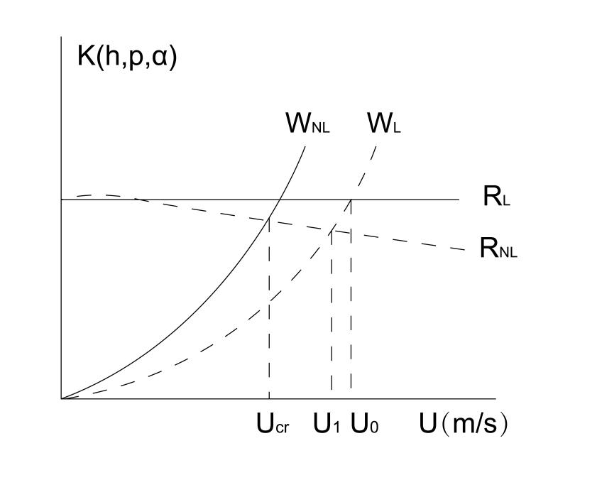
Figure 2. Static wind instability principle
As shown in Fig. 2, the wind load curve WNL rises gradually with the wind speed increase, while the structural stiffness curve RNL decreases. The intersection of these two curves is the critical wind speed for static wind instability Ucr, and the existing static wind load theory described by WL fails to show the nonlinear factor of static wind load caused by the change of effective wind angle of attack and the change curve of static wind load is slow in comparison with WNL. Meanwhile, the resistance curve RL is kept straight without considering the structural resistance with wind speed and structural deformation. Meanwhile, the resistance curve RL is kept linear without considering the variation of structural resistance with wind speed and structural deformation. By analyzing the data in the figure, it can be concluded that the critical wind speed calculated by the linear theory is high, significantly overestimating the structure's static wind stability. To obtain a more accurate solution, a nonlinear method is required.
3.2. Dealing with nonlinear problems
3.2.1. Geometric nonlinearity. Most elastic structures undergo elastic deformation due to changes in internal or external actions. After elastic deformation, the system is placed in a new position, creating a new equilibrium state. Therefore, it is necessary to establish the equilibrium equations based on the new part of the structure. Equilibrium equations are based on the unique position of the system [12]. The core idea of the nonlinear problem is that the equilibrium equations should be developed based on the deformed structure [13].
Suspension bridges are mainly composed of main girders, bridge towers, and main cables, so when constructing their finite element models, it is necessary to combine the two units of cables and girders to complete them. The geometric nonlinear problems of suspension bridges are mainly reflected in the following three aspects: (1) the relaxation of main cables, (2) the coupling effect of axial force and bending moment on main girders and main cables, and (3) large displacement.
At this stage, the equivalent modulus method is most commonly used to calculate central cable relaxation. Its tangential modulus of elasticity can be expressed by the following Eq.6.
\( {E_{eq}}=\frac{E}{1+\frac{{({L_{0}}γ)^{2}}}{12{σ^{3}}}E}\ \ \ (6) \)
Where Eeq is the tangent modulus of elasticity;E is Young's modulus of the primary cable material;L0 is the horizontal projection length; \( γ \) is the tolerance of the leading cable; \( σ \) is the tensile stress of the main line.
3.2.2. Static Wind Load Nonlinearity. Large-span suspension bridge structures are characterized by lightness and flexibility; however, because of this characteristic, the system will be deformed to a certain extent when subjected to static wind loads. A certain degree of deformation will occur under the continuous action of static wind load. When the structure is in hydrostatic wind equilibrium, its position will change significantly, so the effective angle of attack will also vary accordingly. When the system is in static wind equilibrium, its status will be substantially changed, so the effective angle of attack will be changed, and the coefficient of static three-part force will also be changed accordingly. In addition, the static force coefficient will also change. In this way, the static wind load will be nonlinearly altered by the increase of wind speed and the change of the three-part force coefficient. The static wind load will not only be changed by the rise in wind speed but also by the evolution of the coefficient of the third force [14]. At the same time, because the deformation of the bridge deck will have particular differences due to different locations, it will make the bridge deck and the airflow form a non-linear change. The effective angle of attack created by the bridge deck and the airflow changes significantly, so the aerostatic force does not act uniformly on the bridge deck. The aerostatic staff does not work uniformly on the bridge deck, that is, the nonlinear factor of static wind load. Therefore, a reasonable and adequate analysis method needs to be developed. A good and effective way of analysis requires that the aerostatic force on the main girder be considered a function of the effective angle of attack.
This method focuses on the relationship between the variation of the three-part force coefficient and the effective angle of attack. It essentially treats the static wind load as a function of structural deformation. The method has the following characteristics. This method has the following features: (1) When the wind speed is constant, the static wind load acts on the structure, causing it to deform to a certain extent, and the three-part force coefficient will be changed due to the change of the effective wind angle of attack. When the wind speed is constant, the static wind load acts on the structure and makes it deformed to a certain extent, and the three-part force coefficient will be changed accordingly due to the change of the effective wind angle of attack. The static wind load will change accordingly, which further indicates the fact that there is movement in the static wind load; (2) When the wind speed continues to change, the change of wind load parameters will cause the evolution of the static wind load, so it has a more significant nonlinear change characteristic; (3) The angle of attack is a function of the longitudinal coordinates of the bridge, so the static wind load usually changes along the direction of the bridge length, which further indicates its spatial distribution characteristics.
Further, it exhibits its spatial distribution characteristics [7]. This type of method takes wind load parameters into account and is therefore. This type of method can accurately describe the static wind loads, and thus it is an effective nonlinear description method.
3.3. Analysis method of nonlinear static wind stability
Based on considering the geometric nonlinearity of the structure and the nonlinearity of the static wind load, the second type of stabilization problem of the spatial stabilization theory of bridge structures is generalized, and the nonlinear static wind stabilization theory can be reduced to solving the following equilibrium Eq.7.
\( [{K_{e}}(u)+K_{g}^{G+W}(u)]U=F[{F_{H}}(α),{F_{V}}(α),{F_{M}}(α)]\ \ \ (7) \)
Where Ke is the linear elastic stiffness matrix of the structure, Kg is the geometric stiffness matrix of the system. \( α \) is the effective Angle of attack; FH( \( α \) ); FV( \( α \) ); FM( \( α \) ) is the drag force; lift force and lifting moment downwind of the body axis. F is a factor of the function; G and W are dead load and wind force, respectively.
3.4. Internal and external nonlinear iterative programming
Based on ANSYS finite element software, the analysis program is designed using APDL language, and the whole calculation and analysis process is carried out for the suspension bridge's three-dimensional nonlinear static wind stability. The main principles are as follows: when the wind speed is at zero value, the structural equations of equilibrium are calculated to obtain the initial displacement, then the initial wind angle of attack is determined, and based on the wind load, the structural equilibrium equations of equilibrium are calculated for the second time and the structural displacement is obtained by solving the equilibrium equations, and then based on the torsional displacement, the wind angle of attack and the wind load is re-assigned to solve for the structural removal again. Force coefficients used in the two adjacent calculations are sufficiently small in terms of the Euclidean.
To maximize the accuracy of the calculation, the wind load is often required to be applied in a form consistent with the slope load; the use of ANSYS to establish a TABLE array to interpolate the relationship between the effective angle of attack and the three-part force coefficient, the use of a high degree of curve fitting not only has the problem of poor accuracy but also causes the displacement-wind speed curve is too smooth, which has a particular impact on the judgment of the critical wind speed; therefore, it is not adopted; when no instability occurs in the bridge, regardless of the increase in wind speed the deformation and internal force under the wind speed is unique, which can be used to test the accuracy of the calculation procedure. When the bridge is not destabilized, the deformation and internal force of the bridge under the wind speed are unique regardless of the increase in wind speed, and the accuracy of the calculation procedure can be checked accordingly. The process is as follows:
(1) Establish the finite element model of the suspension bridge under the equilibrium state of the bridge, carry out the linear solution under zero wind speed to obtain the structural stiffness matrix, and determine whether the displacement of the bridge meets the accuracy requirements. The structural stiffness matrix determines whether the removal of the bridge meets the accuracy requirements; if not, carry out the adjustment of the rope force and continue to carry out this. If not, the cable adjustment is carried out, and the calculation is continued in the same step;
(2) Extract the central beam torsion angle and determine the effective initial angle of attack based on the initial rise of attack;
(3) Define the initial wind speed U0 and the wind speed increment \( ∆ \) U.
(4) The three-part force coefficient is set concerning the initialized value of the effective angle of attack in the program, and the pre-set wind speed and the height of each structure in the bridge are taken into account in the calculation process. The wind speed and the size of each design in the bridge should be fully considered in the calculation process, and the above factors should also be considered when applying static wind loads.
(5) Solve the problem using ANSYS, if the result is non-convergent, then halve the wind speed step and go to step 4. If the calculated results are in the converged state, then update the value of the three-part force coefficient and obtain the torsion angle, calculate the Euclidean parameter of the three-part force coefficients twice, and determine whether the result is less than the allowable error. The expression of the parameter is shown in Eq.8[15].
\( {\lbrace {\frac{\sum _{j=1}^{N}[{C_{k}}({α_{j}})-{C_{k}}({α_{j-1}})]}{\sum _{j=1}^{N}{[{C_{k}}({α_{j-1}})]^{2}}}^{2}}\rbrace ^{\frac{1}{2}}}≤ep{s_{k}}\ \ \ (8) \)
N is the number of nodes to which the static wind load is applied; Ck is the three-part force coefficient;epsk is the allowable error. If the results obtained are better than the epsk is smaller than epsk, then the development of this calculation is considered to be converged, and the wind speed can be increased according to the preset step size. Otherwise, the wind speed can be increased according to the preset step size. If not, then halve the wind speed step and return to steps 4 and 5, if the number of iterations exceeds the specified value, then increase the wind speed according to the preset step size. If the number of iterations exceeds the fixed value, the calculation result is not converged, and the result is output.
Check if the calculation of the preset wind speed is completed; if so, terminate the calculation process; otherwise, continue to repeat steps 4 and 5. If the analysis is conducted, the process will be removed; otherwise, repeat steps 4 and 5 until the calculation is completed.
3.5. Analysis of the whole process of static wind stability of Fuyuan Avenue Bridge
Fuyuan Avenue Bridge is the object of study. The main bridge adopts a double-surface self-anchored concrete suspension bridge. The anchor cable span is divided into the main and side spans, a total length of 1305m a standard width of 26m. Two main cables are parabolic, with a main spanning ratio of 1/12.75; the upper end of the main cable is connected to the upper cable clamps, and the following is anchored to the boom beams. The main bridge adopts a tower-beam-pier consolidation system. Finite element simulation of the Fuyuan Avenue Bridge is carried out by using finite element software MIDAS. The three-dimensional right-angle coordinate system is established, and the finite element model of the bridge formation state is shown in Figure 3:
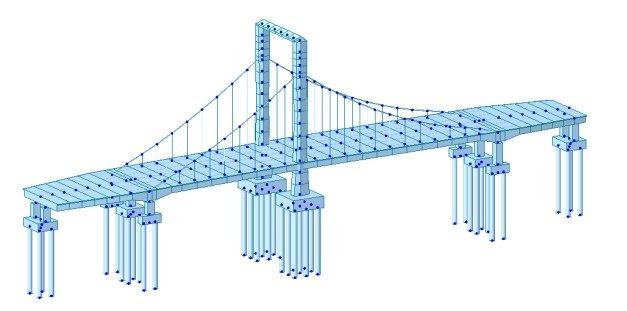
Figure 3. The drawing of the bridge is a finite element calculation model of the bridge state
Run the simulation program to simulate the impact of different wind speeds on the bridge structure in real scenarios, set the wind speed to 40m/s in the initial state, the wind angle of attack is +1°, and gradually increase the wind speed in the experimental process, each time to increase the wind speed of 5m/s, in the process of the experiment on the discovery that when the wind speed of 108m/s, the bridge structure caused a more significant impact, this time, the system appeared to be a phenomenon of nonlinear static wind instability. Table 1 below shows the values of the central girder span center position with the change in wind speed.
Table 1. The numerical value of displacement at mid-span position
Wind Speed | Transversal Displacement | Vertical Displacement | Torsion Displacement |
40 | 0.140 | -0.046 | 0.014 |
45 | 0.199 | -0.055 | 0.018 |
50 | 0.273 | -0.071 | 0.023 |
55 | 0.363 | -0.083 | 0.030 |
60 | 0.472 | -0.098 | 0.037 |
65 | 0.600 | -0.106 | 0.041 |
70 | 0.749 | -0.111 | 0.048 |
75 | 0.921 | -0.116 | 0.057 |
80 | 1.118 | -0.120 | 0.069 |
85 | 1.341 | -0.116 | 0.096 |
90 | 1.592 | -0.102 | 0.126 |
95 | 1.872 | -0.051 | 0.170 |
100 | 2.183 | -0.011 | 0.235 |
The following figure shows the variation of mid-span displacement with wind speed for the main beam, and the mechanical behavior of the whole process is shown in Figures 4, 5, 6, below:
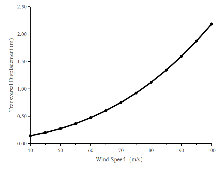
Figure 4. The process of transverse displacement change in the span
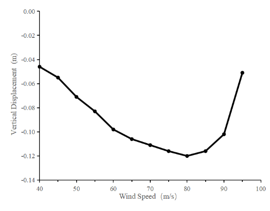
Figure 5. Vertical displacement change process in the span
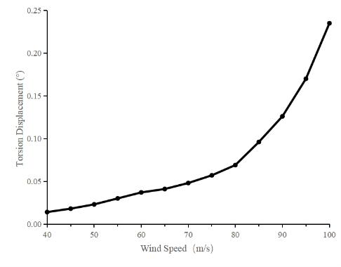
Figure 6. The process of torsional displacement change in the span
The critical wind speed for nonlinear instability of the whole bridge under +1° initial angle of attack is 95 m/s. It can be seen from Fig:
(1) When the wind speed is low, the displacement in each direction shows a linear trend. When the wind speed is gradually increased, the spatial deformation of the structure is intensified, which shows explicitly a nonlinear geometric relationship. The reason is that when the wind speed is at a lower value, the torsional deformation of the main beam tends to be at a lower level, which makes the non-linear relationship between the torsion angle of the main shaft and the three-part force coefficient not entirely highlighted. Therefore it can be assumed that the two are in a linear relationship.
(2) If the wind speed is low, the main beam shows apparent downward deflection in the span. The deflection increases with the wind speed and reaches the maximum at the wind speed of 80m/s, and then the main beam continues to deflect upward, and the trend is getting bigger and bigger. When the structure is at +1° angle of attack, if the lift coefficient of the main girder is less than zero value, then the main beam will show a downward deflection pattern at the beginning, and when the wind speed is increased to increase the torsion angle of the main girder, which increases the deflection with the wind speed.
When the wind speed is increased, the torsion angle of the main beam is increased, which further leads to the lift coefficient changing from negative to positive, and the wind load is changed from downward to upward. At the same time, the degree of non-linearity is increased, which finally makes the main beam show an upward deflection pattern.
(3) When the wind speed gradually increases up to 95m/s, the displacement of the nodes in the span will increase instantaneously, and the increased removal mainly includes vertical and torsion displacement, which will lead to the coupling instability of the bridge in this case.
4. Conclusion
In this paper, the incremental and internal and external two-fold iteration method is selected in the research process, which is the current mainstream calculation method. This method can quickly calculate the data of various influencing factors, and the calculation results are more reliable, which can better solve the main influencing factors of static wind instability and avoid the disadvantages of inaccurate results in the traditional linear calculation method. This paper combed and summarized the corresponding fundamental theories of the predecessors for a detailed introduction, so the lack of practice generated data support.
Bridges are generally constructed in a natural wind field. The turbulence in the wind field affects the three-part force coefficient of the main girder, which is an essential factor affecting the stability of hydrostatic winds. The turbulence can be studied in depth in future research work.
References
[1]. Ge, Y.J. Aerodynamic challenge and limitation in long-span cable-supported bridges. Proceedings of the 2016 World Congress on Advances in Civil, Environmental, and Materials Research; Jeju island, Republic of Korea, 28 August–1 September 2016.
[2]. Hirai, A.; Okauchi, I.; Ito, M.; Miyata, T. Studies on the critical wind velocity for suspension bridges. Proceedings of the International Research Seminar on Wind Effects on Buildings and Structures; Ottawa, ON, Canada, 11–15 September 1967; Volume 2, pp. 81-103.
[3]. Cheng, J.; Jiang, J.J.; Xiao, R.C.; Xiang, H.F. Nonlinear aerostatic stability analysis of Jiang Yin suspension bridge. Eng. Struct.; 2002; 24, pp. 773-781. [DOI: https://dx.doi.org/10.1016/S0141-0296(02)00006-8]
[4]. Imai, K.; Frangopol, D.M. Geometrically nonlinear finite element reliability analysis of structural systems. I: Theory. Comput. Struct.; 2000; 77, pp. 677-691. [DOI: https://dx.doi.org/10.1016/S0045-7949(00)00010-9]
[5]. Liang, H.L. Reliability Analysis of Static Wind Instability of Steel Truss Pedestrian Suspension Bridge. Ph.D. Thesis; Xi’an University of Science and Technology: Xi’an, China, 2018.
[6]. Chen, W.Z.; Tang, T.; Xu, J. Cable-stayed bridge structural system reliability assessment theory research progress. J. Bridge Constr.; 2006; 4, pp. 67-70.
[7]. Zhang, T., Cui, X., Guo, W., Zou, Y., & Qin, X. (2023). Static wind reliability analysis of long-span highway cable-stayed bridge in service. Applied Sciences, 13(2), 749. doi:https://doi.org/10.3390/app13020749
[8]. Xie Jiali. Analysis of nonlinear static wind instability pattern mechanism and parametric study of large-span suspension bridge [D]. Supervisor:Ma Cunming. Southwest Jiaotong University,2015
[9]. Shi, Yan Li, Feng Wang, and Wen Da Wang. "Preliminary Research on Effective Length of Concrete Filled Steel Tubular Columns in Sway Frame", Advanced Materials Research, 2012.
[10]. Guang ZL. Static wind nonlinear stability analysis of large-span suspension bridge[D]. Chang'an University,2022.
[11]. Virote Boonyapinyo, Hitoshi Yamada, Toshio Miyata. "Wind‐Induced Nonlinear Lateral‐Torsional Buckling of Cable‐Stayed Bridges", Journal of Structural Engineering, 1994
[12]. Fenghui Dong, Jin Cheng. "A new method for estimation of aerostatic stability safety factors of cable-stayed bridges", Proceedings of the Institution of Civil Engineers - Structures and Buildings, 2017
[13]. Xie Xuefeng, Luo Xiheng. Research on the analysis method of suspension bridge based on ANSYS[J]. China Engineering Science, 2012, 14 (5): 101-105
[14]. LIANG Shuo, ZENG Qingyuan, ZHANG Qisen. A review of ultimate bearing capacity analysis of large-span concrete cable-stayed bridges[J]. Journal of Changsha Transportation Journal of Changsha Institute of Transportation, 1997, 13(3): 39-46
[15]. Chuanxin Hu, Zhiyong Zhou, Kangjian Yan. "Wind-Induced Stability of a Cable-Stayed Bridge with Double Main Spans of 1,500m and a Twin-Box Section", Journal of Bridge Engineering, 2020
Cite this article
Li,J. (2024). Stability analysis of long-span bridge under static wind load. Applied and Computational Engineering,56,1-11.
Data availability
The datasets used and/or analyzed during the current study will be available from the authors upon reasonable request.
Disclaimer/Publisher's Note
The statements, opinions and data contained in all publications are solely those of the individual author(s) and contributor(s) and not of EWA Publishing and/or the editor(s). EWA Publishing and/or the editor(s) disclaim responsibility for any injury to people or property resulting from any ideas, methods, instructions or products referred to in the content.
About volume
Volume title: Proceedings of the 4th International Conference on Materials Chemistry and Environmental Engineering
© 2024 by the author(s). Licensee EWA Publishing, Oxford, UK. This article is an open access article distributed under the terms and
conditions of the Creative Commons Attribution (CC BY) license. Authors who
publish this series agree to the following terms:
1. Authors retain copyright and grant the series right of first publication with the work simultaneously licensed under a Creative Commons
Attribution License that allows others to share the work with an acknowledgment of the work's authorship and initial publication in this
series.
2. Authors are able to enter into separate, additional contractual arrangements for the non-exclusive distribution of the series's published
version of the work (e.g., post it to an institutional repository or publish it in a book), with an acknowledgment of its initial
publication in this series.
3. Authors are permitted and encouraged to post their work online (e.g., in institutional repositories or on their website) prior to and
during the submission process, as it can lead to productive exchanges, as well as earlier and greater citation of published work (See
Open access policy for details).
References
[1]. Ge, Y.J. Aerodynamic challenge and limitation in long-span cable-supported bridges. Proceedings of the 2016 World Congress on Advances in Civil, Environmental, and Materials Research; Jeju island, Republic of Korea, 28 August–1 September 2016.
[2]. Hirai, A.; Okauchi, I.; Ito, M.; Miyata, T. Studies on the critical wind velocity for suspension bridges. Proceedings of the International Research Seminar on Wind Effects on Buildings and Structures; Ottawa, ON, Canada, 11–15 September 1967; Volume 2, pp. 81-103.
[3]. Cheng, J.; Jiang, J.J.; Xiao, R.C.; Xiang, H.F. Nonlinear aerostatic stability analysis of Jiang Yin suspension bridge. Eng. Struct.; 2002; 24, pp. 773-781. [DOI: https://dx.doi.org/10.1016/S0141-0296(02)00006-8]
[4]. Imai, K.; Frangopol, D.M. Geometrically nonlinear finite element reliability analysis of structural systems. I: Theory. Comput. Struct.; 2000; 77, pp. 677-691. [DOI: https://dx.doi.org/10.1016/S0045-7949(00)00010-9]
[5]. Liang, H.L. Reliability Analysis of Static Wind Instability of Steel Truss Pedestrian Suspension Bridge. Ph.D. Thesis; Xi’an University of Science and Technology: Xi’an, China, 2018.
[6]. Chen, W.Z.; Tang, T.; Xu, J. Cable-stayed bridge structural system reliability assessment theory research progress. J. Bridge Constr.; 2006; 4, pp. 67-70.
[7]. Zhang, T., Cui, X., Guo, W., Zou, Y., & Qin, X. (2023). Static wind reliability analysis of long-span highway cable-stayed bridge in service. Applied Sciences, 13(2), 749. doi:https://doi.org/10.3390/app13020749
[8]. Xie Jiali. Analysis of nonlinear static wind instability pattern mechanism and parametric study of large-span suspension bridge [D]. Supervisor:Ma Cunming. Southwest Jiaotong University,2015
[9]. Shi, Yan Li, Feng Wang, and Wen Da Wang. "Preliminary Research on Effective Length of Concrete Filled Steel Tubular Columns in Sway Frame", Advanced Materials Research, 2012.
[10]. Guang ZL. Static wind nonlinear stability analysis of large-span suspension bridge[D]. Chang'an University,2022.
[11]. Virote Boonyapinyo, Hitoshi Yamada, Toshio Miyata. "Wind‐Induced Nonlinear Lateral‐Torsional Buckling of Cable‐Stayed Bridges", Journal of Structural Engineering, 1994
[12]. Fenghui Dong, Jin Cheng. "A new method for estimation of aerostatic stability safety factors of cable-stayed bridges", Proceedings of the Institution of Civil Engineers - Structures and Buildings, 2017
[13]. Xie Xuefeng, Luo Xiheng. Research on the analysis method of suspension bridge based on ANSYS[J]. China Engineering Science, 2012, 14 (5): 101-105
[14]. LIANG Shuo, ZENG Qingyuan, ZHANG Qisen. A review of ultimate bearing capacity analysis of large-span concrete cable-stayed bridges[J]. Journal of Changsha Transportation Journal of Changsha Institute of Transportation, 1997, 13(3): 39-46
[15]. Chuanxin Hu, Zhiyong Zhou, Kangjian Yan. "Wind-Induced Stability of a Cable-Stayed Bridge with Double Main Spans of 1,500m and a Twin-Box Section", Journal of Bridge Engineering, 2020