


1. Introduction
In view of the current dramatic worldwide climate change and serious environmental pollution, the exploration of new energy sources such as solar energy, wind energy, and hydrogen energy has gradually attracted more interest. Among them, solar energy has attracted the most attention due to its widely available, environmentally friendly, renewable, sustainable, energy independence, energy storage options, and so on [1-3]. Therefore more and more paper is devoted to the study of photovoltaic power generation. Photovoltaic power generation systems are mainly categorized into stand-alone photovoltaic power generation systems and grid-connected photovoltaic power generation systems. This paper focuses on grid-connected PV power generation systems, which usually do not contain a transformer. As shown in Figure 1, this transformerless inverter has two types of grid-connections in two ways, a single-stage structure and a two-stage structure [4-8]. In these systems, the inverter directly converts the DC power generated by the PV panels into AC power, which is then injected into the main grid without the need for an intermediate transformer. The lack of this transformer reduces some of the energy losses in the energy conversion, improves the efficiency of the system, and is also characterized by lightweight. Solar photovoltaic (PV) technology is the direct conversion of solar energy into electricity, which is converted into grid-compliant alternating current (AC) by a grid-connected inverter and then connected to the utility grid. To improve the system efficiency and power density of power electronics, transformerless inverters are commonly used in industry to fulfill this need. However, the lack of a transformer can also lead to many problems, such as a lack of electrical isolation, the presence of electrical interference, and grounding problems. As far as lack of electrical isolation is concerned, due to the parasitic capacitance of the PV cells to the ground, in the absence of a transformer, electrical isolation is lost between the grid and the PV system, creating a common-mode loop with the earth. The high-frequency oscillation of common-mode voltage will bring about leakage current, which will lead to current distortion, cause equipment damage, and even lead to personal injury. Therefore, it is important to suppress the leakage current, and people must strictly detect and control its amplitude [2]. Therefore, the subject of this paper is the leakage current suppression technique for transformerless inverters. According to domestic and international studies, it is found that the leakage current mainly depends on the panel parasitic capacitance value and the common-mode voltage, which in turn depends on the modulation strategy and topology [9-11]. On the one hand, leakage current loop channels are avoided by changing the topology of the grid-connected transformerless inverter. On the other hand, higher frequency harmonics are filtered out by adding filters. Both solutions are improvements from the hardware side, which can increase the cost and the complexity of the circuit. By contrast, it has been shown that it is possible to suppress common-mode voltages software-wise, by improving the Space Vector Pulse Width Modulation (SVPWM) modulation strategy to reduce the generation of common-mode voltages. This approach is more economical and maneuverable. This method is more economical and operable.
|
|
(a) | (b) |


Figure 1. Structure of transformerless inverter: (a) single stage [4]; (b) two-stage [4].
This paper first takes a three-level inverter as an example to analyze the circuit principle as well as the optimized topology. Secondly, it studies the development of leakage current suppression technology in recent years and elaborates on the causes and three solutions of leakage current in inverters. Finally, we combine the characteristics of leakage current solutions to improve the system efficiency based on leakage current suppression.
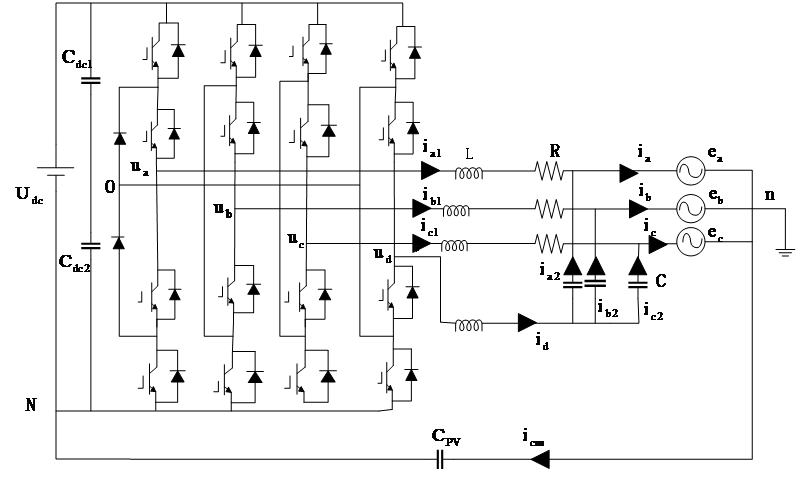
Figure 2. Grid-connected three-level, four-leg inverter clamped at the neutral point [5]
2. The basics and configuration of a three-phase, four-leg inverter
Four parallel-connected legs make up the inverter. A percentage of the total output power is under the control of each leg. A DC link, which is attached to the inverter’s input, usually gets its DC power from a battery bank or photovoltaic array. The neutral clamp is this inverter’s primary feature. Grid voltage is represented by ej in Figure 2, the current which is connected to the grid is indicated by ij, and ua, ub, uc, ud means output voltage of leg at point n [5].
3. Reasons for the existence of leakage currents
Without a transformer, electrical isolation between the PV system and the grid is lost. Also, common mode (CM) loops due to parasitic capacitance between the PV cell and the ground. Leakage currents result from the higher frequency oscillation of the voltage of the common node, which damages equipment and injures people. It also causes current distortion. As a result, its amplitude needs to be properly identified and managed [2]. According to reference [5], the mathematical formulas for the traditional topology are derived, which allows for the calculation of the leakage current’s magnitude as well as the display of its source.
\( \begin{cases}\begin{matrix}{u_{a}}=L\frac{d{i_{a1}}}{dt}+{i_{a1}}R+{e_{a}}+{u_{nN}} \\ {u_{b}}=L\frac{d{i_{b1}}}{dt}+{i_{b1}}R+{e_{b}}+{u_{nN}} \\ \begin{matrix}{u_{c}}=L\frac{d{i_{c1}}}{dt}+{i_{c1}}R+{e_{c}}+{u_{nN}} \\ {u_{d}}=L\frac{d{i_{d}}}{dt}+\frac{1}{C}\int \frac{1}{3}{i_{d}}dt+e+{u_{nN}} \\ \end{matrix} \\ \end{matrix}\end{cases} \) (1)
For the 3 phase symmetric grid
\( {e_{a}}+{e_{b}}+{e_{c}}=0 \) (2)
Common mode voltage is
\( {u_{cm}}=\frac{{u_{a}}+{u_{b}}+{u_{c}}+{u_{d}}}{4} \) (3)
Leakage current, let \( {{i_{1}}=i_{a1}}+{i_{b1}}+{i_{c1}} \) , \( {{i_{2}}=i_{a2}}+{i_{b2}}+{i_{c2}} \)
\( {i_{cm}}={i_{a}}+{i_{b}}+{i_{c}}={i_{1}}+{i_{d}}={{i_{a1}}+{i_{b1}}+{i_{c1}}+i_{a2}}+{i_{b2}}+{i_{c2}} \) (4)
Equation of capacitance voltage should be
\( {u_{nN}}=\frac{1}{{C_{PV}}}\int {i_{cm}}dt \) (5)
Adding all equations in first part, and then combine (2) with (5), then
\( 4{u_{cm}}=L\frac{d{i_{cm}}}{dx}dt+{i_{1}}R+\frac{1}{C}\int {i_{d}}dt+e+\frac{4}{{C_{PV}}}\int {i_{cm}}dt \) (6)
As a result, there are two ways to decrease leakage current: first, indirectly by slowing down the rate at which the voltage of common node changes using a control strategy [5]. Second, in accordance with the hardware circuit principle, the topology of the circuit is designed to restrain the leakage current [5].
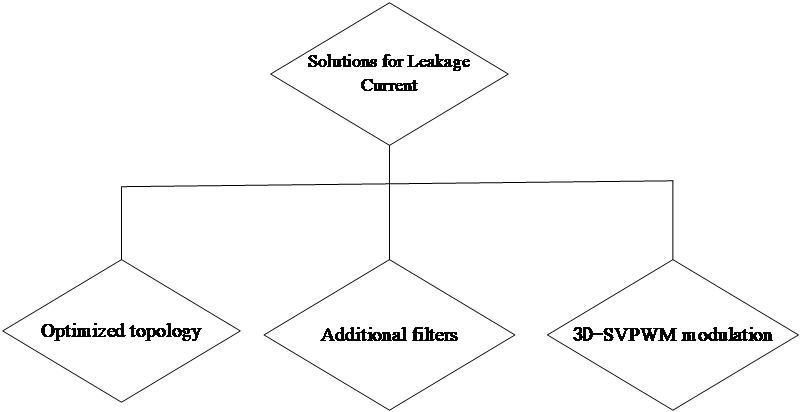
Figure 3. Overview of leakage current suppression schemes [5]
4. Solutions for Leakage Current
Figure 3 illustrated the classifications of recent leakage current suppression schemes.
4.1. Changing the topology of a circuit
According to the reference [5], the circuit topology can be altered; Figure 4 depicts the better topology 1. As seen in Figure 2, the revised topology 1 links the filter capacitor’s common point to the grid side’s neutral point n. In order to minimize the number of excitation sources from two to one, the optimized topology 1 short-circuits several components and adds a connecting line, which lowers the leakage current icm. The topology in question creates an extra loop to minimize leakage current, but it also brings current into the three-phase grid’s neutral point, increasing the current’s harmonic distortion. Although the gate side current Total Harmonic Distortion (THD) rises with the improved topology 1, the leakage current is further suppressed [5]. The division of the excitation source’s produced current into several branches, as depicted in Figure 5, theoretically achieves the effect of leakage current suppression by reducing the leakage current. By connecting a smaller resistor in series from the filter capacitor to the branch at point O, the loop current issue is resolved and the topology is stabilized [5]. Furthermore, by developing a mathematical model and performing simulations like FFT analysis, reference [5] confirms that this topology can lower the leakage current. It also examines the voltage differential between the two capacitors on the side of DC, as well as the leakage currents and common-mode voltages of the optimized topology 2.

Figure 4. optimized topology 1 [5].
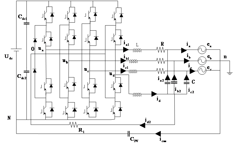
Figure 5. Optimized topology 2 [5].
4.2. Additional filters
The reference [6] uses a modified LCL (MLCL) filter (Fig. 6) to lower icm. To give higher-frequency leakage currents and higher-frequency harmonic currents a low-impedance flow channel, a tiny capacitor is connected to neutral point. In order to suppress the neutral current as well as the resonant currents of common node, the original filter capacitor circuit is linked in series with a big resistor. Ultimately, a double closed-loop control further reduces the common-mode resonant current, and simulation confirms the efficiency of the plan.
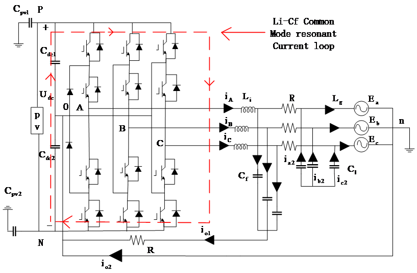
Figure 6. Structure diagram of grid-connected system of three-level PV inverter with MLCL filter [6].
A filter with an LCCL structure (shown in Fig. 7) can be used in reference [2] to suppress the leakage current by keeping most of the leakage current trapped inside the transformer instead of circulating on the ground. However, LCCL filters suffer from resonance problems, which can lead to severe overcurrent as well as losses. Therefore, reference [2] proposes to build a CM equivalent circuit and suppress it by active damping based on controlling i_cm in a closed loop. Without reviewing this method too much, this paper focuses on analyzing the restraining mechanism of the inverter icm of the LCCL structure in this section. From Figure 7, it can be seen that the LCCL traps the current in the inverter by providing an additional CM current bypass [2]. In order to explain the leakage current suppression principle of the LCCL filter more precisely, the transfer function and bode plot of CM voltage are also listed in the reference [2]. By comparing the bode plots of conventional LCL and LCCL, it is found that as the frequency gets higher, the gain of LCCL is significantly smaller than that of the LCL filter, which effectively shows that the effectiveness of LCCL filter [2].
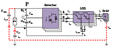
Figure 7. 3-phase transformerless inverter equipped with an LCCL filter [2].
4.3. Software Modulation Strategy
It is explained in reference [1] that three-level inverters can produce higher voltages while exhibiting lower ripple current. The drawbacks of three-level inverters and even multilevel inverters have also been made up for by the development of various modulation techniques. The complexity of multilevel control is decreased by the enhancement and simplicity of the SVPWM control method. Nevertheless, there are several disadvantages to traditional SVPWM modulation. For example, in low-power applications, the benefits of SVPWM might not be as evident because the requirements might be met with less complexity by using straightforward pulse width modulation approaches. It is not possible to obtain more precise voltage and current control for high power applications, nor is it suitable for applications that demand precise control. A three-level inverter’s voltage vector space and space vector distribution are depicted in Figure 8. Sa, Sb, and Sc are used to denote the space vectors. There are 27 space vectors that match the 27 switching states. Without transformer isolation, this modulation method for the traditional SVPWM modulation technique creates significant leakage currents, potentially endangering the safety of people and equipment [5].
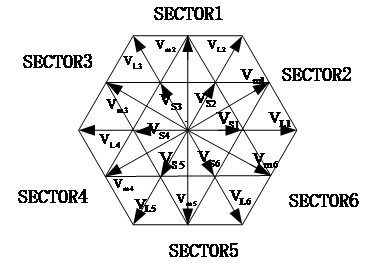
Figure 8. Three-level inverter vector space [5]
In the reference [3], the modulation approach for 3D-SVPWM has been proposed. This modulation approach has the advantage of allowing for more exact control over the voltage vector, which results in higher-quality output voltage waveforms. This lessens electromagnetic interference and minimizes harmonic and amplitude distortion. Furthermore, by using finer voltage control, 3D-SVPWM lowers the output voltage’s harmonic content. Higher inverter efficiencies can be attained because 3D-SVPWM generates a voltage waveform that is more akin to a sinusoidal waveform. This enhances system performance and lowers energy losses. For applications needing fine control, 3D-SVPWM makes it possible to manage voltage and current more precisely. 3D-SVPWM increases the system’s electromagnetic compatibility and minimizes electromagnetic interference because of its more accurate control and reduced harmonic content. Power factor correction and inverter drives are only two examples of the many frequency range applications where 3D-SVPWM can be applied. With more control degrees provided by 3D-SVPWM, it is feasible to tailor the control to the demands of a particular application in order to satisfy various efficiency and performance standards. The reference [3] proposes the 3D-SVPWM modulation approach to balance the 0-sequence voltage pulses in each switching cycle. Its positive and negative areas are equal for the voltage of common node pulses. To stop the leakage current, it will generate a smooth voltage at harmonic frequency. By lowering the voltage’s amplitude, this modulation method lowers icm. It successfully resolves the issues of low integrated efficiency. It lowers system losses and raises the quality of grid-connected current. It is imperative to meet the critical needs of grid development and modern energy systems in order to realize the growth of the solar energy production industry [5]. For these reasons, 3D-SVPWM is far superior to traditional SVPWM in terms of voltage purity, harmonic content, efficiency, and control precision.
5. Advantages and disadvantages of three leakage current suppression schemes
For the optimized topology, the advantages are reduced grid current ripple in the output filter [11], lower THD to avoid more switching losses. And enhanced reactive power control [8]. By choosing an optimized circuit topology, the probability of leakage current can be reduced and the safety of the electrical system can be improved. Optimized topologies help to reduce the risk of the electrical system by reducing the probability of current bypassing the normal circuit paths, thus improving safety. Some optimized topologies reduce energy losses and improve the efficiency of electrical systems. Optimized topologies help to improve the quality of the voltage waveform and reduce the harmonic content of the voltage waveform, thereby improving the performance of the electrical system. For the addition of filters, the advantage is the reduction of electromagnetic interference. Filters are effective in reducing electromagnetic interference, especially high-frequency noise and harmonics. This helps to improve the performance and reliability of electrical equipment and reduces the effect of electromagnetic interference on other equipment. Filters can improve voltage quality by reducing the distortion and harmonic content of the voltage waveform. This is important for applications that require a high-quality voltage waveform, such as motor control and power factor correction. Some filters can reduce current leakage, especially leakage problems associated with EMI or harmonics. By reducing current leakage and minimizing EMI, filters help to improve the safety of electrical systems and reduce the potential danger of leakage currents to personnel and equipment. The disadvantage is that filters typically require additional hardware and equipment, which can increase system costs. Filters typically require additional power consumption to operate, especially when the filter is activated. This may affect the overall efficiency of the system. The design, commissioning, and maintenance of filters may be complex and require specialized knowledge. Filters typically require additional space and therefore may not be suitable for space-constrained applications.
Table 1. Advantages and disadvantages of three leakage current suppression schemes
Three solutions | Advantages | Disadvantages |
Optimized topology | • Effective leakage current suppression [9, 11] • Reduces the possibility of current bypassing normal circuit paths | • Complex circuitry and high cost [8] • Additional hardware equipment increases system costs • Not suitable for applications where space is limited |
Adding filters | • Separates leakage currents from common mode resonant currents, improving the ability to suppress high-frequency harmonic currents [6] • Provides additional leakage current bypass, where leakage currents are trapped in the inverter and do not circulate through ground [6] • Improves voltage quality [10] • Improves appliance safety | • Increase in system cost [6] • Reduce the overall operating efficiency, need additional power consumption to activate the filter • Complicated design, commissioning and maintenance |
Modulation | • Precise voltage control, greatly reducing harmonic content • High quality voltage waveform output, suitable for applications requiring high voltage quality and performance • Improve electromagnetic compatibility | • high-performance microcontroller processing, computational control is complex • high hardware requirements, increase system costs • Not applicable to some low-power applications |
For the software side of the 3D-SVPWM modulation method, the advantages are that 3D-SVPWM reduces the harmonic content of the output current through more precise voltage control. This helps to minimize leakage current problems caused by harmonics.3D-SVPWM generates a high-quality output voltage waveform that is closer to a sinusoidal waveform, reducing the distortion of the voltage waveform and thus reducing the leakage current. 3D-SVPWM allows for very precise voltage control, which is very helpful in reducing the leakage current, especially in applications where high voltage quality is required. 3D-SVPWM is suitable for applications that require high voltage quality and performance, such as motor drives and power factor correction. Due to lower harmonic content and more precise control, 3D-SVPWM reduces electromagnetic interference and improves the electromagnetic compatibility of electrical systems. The disadvantage is that 3D-SVPWM is more complex to compute and control, and usually requires a high-performance microcontroller or digital signal processor to implement. This may increase the cost and complexity of the system. 3D-SVPWM requires high-speed switching devices for efficient voltage control. This may increase the cost of the hardware. The benefits of 3D-SVPWM are usually more apparent in specific applications where high voltage quality and performance are required. For some low-power applications, such a complex control method may not be needed. Table 1 summarizes the advantages and disadvantages of each of the three schemes.
6. Future development and technical challenges
Based on the three scenarios totaled in this paper, the addition of filters can provide significant advantages in reducing leakage currents and improving the performance of electrical systems, but factors such as cost, power consumption, complexity, and applicability need to be considered. Optimizing the circuit topology to reduce leakage current is usually beneficial to improve the safety and performance of electrical systems. However, factors such as complexity, cost, and applicability need to be considered to determine if a particular optimized topology is worthwhile.3D-SVPWM is highly advantageous for reducing leakage current and improving electrical system performance, but its computational complexity, hardware requirements, and applicability need to be considered. In conclusion, this paper synthesizes circuit complexity, cost, and suppression efficiency, and in the future, a combination of optimized topologies, additional filters, and software modulation strategies may yield a compromise.
7. Conclusion
This paper primarily presents the topology and basic principles of a three-level inverter. It also reviews the three solutions suggested in the existing reference for the leakage current problem, including one that involves optimizing the topology. Using this inverter in Figure 2 as an example, the paper reviews the topology scheme that can effectively inhibit the leakage current. The second is to add filters, the LCCL filter and the enhanced MLCL filter, respectively. Third, the advantages and disadvantages of the 3D-SVPWM modulation method—which was suggested in the are explained and contrasted with the traditional SVPWM modulation strategy. This paper presents a proposal that integrates the benefits and drawbacks of multiple solutions. It also compares and summarizes the characteristics of those solutions. Based on the combination of the three solutions, it is thought that the cost and suppression efficiency may be balanced.
References
[1]. Zhang, Guangyu. “Development Status of Space Vector Pulse Width Modulation (SVPWM) Control Method for Multi-Level Inverter.” Journal of Physics: Conference Series. Vol. 2479. No. 1. IOP Publishing, 2023.
[2]. Wang, C., Zhao, R., Poh, C. L., Xu, H., & Yan, Q. (2019). Leakage current suppression and common-mode resonance active damping for LCCL-filtered transformerless three-phase PV inverter. Stevenage: The Institution of Engineering & Technology.
[3]. Estévez-Bén, A.A.; Alvarez-Diazcomas, A.; Macias-Bobadilla, G.; Rodríguez-Reséndiz, J. Leakage Current Reduction in Single-Phase Grid-Connected Inverters—A Review. Appl. Sci. 2020, 10, 2384.
[4]. Kibria, M.F.; Elsanabary, A.; Tey, K.S.; Mubin, M.; Mekhilef, S. A Comparative Review on Single Phase Transformerless Inverter Topologies for Grid-Connected Photovoltaic Systems. Energies 2023, 16, 1363.
[5]. Dong, Shi, Jiajun Liang, and Jiaxin Yang. “The leakage current suppression of transformerless three-level photovoltaic grid-connected inverter.” Journal of Physics: Conference Series. Vol. 2479. No. 1. IOP Publishing, 2023.
[6]. Chen, W., Zhang, G., He, H. and Wu, C. (2022). A new design and control method to improve the suppression of common-mode resonant and leakage currents in three-level inverters with LCL filters. Physics Letters: conference series, 2369(1), 012057.
[7]. Zhang, Guangyu. “Development Status of Space Vector Pulse Width Modulation (SVPWM) Control Method for Multi-Level Inverter.” Journal of Physics: Conference Series. Vol. 2479. No. 1. IOP Publishing, 2023.
[8]. ZHANG Xing, WU Mengze, WANG Mingda, WANG Pingzhou, FU Xinxin, ZHAO Tao. A review of leakage current suppression and power equalization control for single-phase photovoltaic cascaded multilevel inverters[J]. Power system automation, 2023,47(9):202-215.
[9]. Ponrekha A, Sahaya, et al. “A topology review and comparative analysis on transformerless grid‐connected photovoltaic inverters and leakage current reduction techniques.” IET Renewable Power Generation (2022).
[10]. W. Li, Y. Gu, H. Luo, W. Cui, X. He and C. Xia, “Topology Review and Derivation Methodology of Single-Phase Transformerless Photovoltaic Inverters for Leakage Current Suppression,” IEEE Transactions on Industrial Electronics, vol. 62, no. 7, pp. 4537-4551, July 2015.
[11]. Estévez-Bén, A.A.; Alvarez-Diazcomas, A.; Macias-Bobadilla, G.; Rodríguez-Reséndiz, J. Leakage Current Reduction in Single-Phase Grid-Connected Inverters—A Review. Appl. Sci. 2020, 10, 2384.
Cite this article
Wang,L. (2024). Recent advances in leakage current suppression techniques for three-level inverters. Applied and Computational Engineering,62,315-323.
Data availability
The datasets used and/or analyzed during the current study will be available from the authors upon reasonable request.
Disclaimer/Publisher's Note
The statements, opinions and data contained in all publications are solely those of the individual author(s) and contributor(s) and not of EWA Publishing and/or the editor(s). EWA Publishing and/or the editor(s) disclaim responsibility for any injury to people or property resulting from any ideas, methods, instructions or products referred to in the content.
About volume
Volume title: Proceedings of the 2nd International Conference on Mechatronics and Smart Systems
© 2024 by the author(s). Licensee EWA Publishing, Oxford, UK. This article is an open access article distributed under the terms and
conditions of the Creative Commons Attribution (CC BY) license. Authors who
publish this series agree to the following terms:
1. Authors retain copyright and grant the series right of first publication with the work simultaneously licensed under a Creative Commons
Attribution License that allows others to share the work with an acknowledgment of the work's authorship and initial publication in this
series.
2. Authors are able to enter into separate, additional contractual arrangements for the non-exclusive distribution of the series's published
version of the work (e.g., post it to an institutional repository or publish it in a book), with an acknowledgment of its initial
publication in this series.
3. Authors are permitted and encouraged to post their work online (e.g., in institutional repositories or on their website) prior to and
during the submission process, as it can lead to productive exchanges, as well as earlier and greater citation of published work (See
Open access policy for details).
References
[1]. Zhang, Guangyu. “Development Status of Space Vector Pulse Width Modulation (SVPWM) Control Method for Multi-Level Inverter.” Journal of Physics: Conference Series. Vol. 2479. No. 1. IOP Publishing, 2023.
[2]. Wang, C., Zhao, R., Poh, C. L., Xu, H., & Yan, Q. (2019). Leakage current suppression and common-mode resonance active damping for LCCL-filtered transformerless three-phase PV inverter. Stevenage: The Institution of Engineering & Technology.
[3]. Estévez-Bén, A.A.; Alvarez-Diazcomas, A.; Macias-Bobadilla, G.; Rodríguez-Reséndiz, J. Leakage Current Reduction in Single-Phase Grid-Connected Inverters—A Review. Appl. Sci. 2020, 10, 2384.
[4]. Kibria, M.F.; Elsanabary, A.; Tey, K.S.; Mubin, M.; Mekhilef, S. A Comparative Review on Single Phase Transformerless Inverter Topologies for Grid-Connected Photovoltaic Systems. Energies 2023, 16, 1363.
[5]. Dong, Shi, Jiajun Liang, and Jiaxin Yang. “The leakage current suppression of transformerless three-level photovoltaic grid-connected inverter.” Journal of Physics: Conference Series. Vol. 2479. No. 1. IOP Publishing, 2023.
[6]. Chen, W., Zhang, G., He, H. and Wu, C. (2022). A new design and control method to improve the suppression of common-mode resonant and leakage currents in three-level inverters with LCL filters. Physics Letters: conference series, 2369(1), 012057.
[7]. Zhang, Guangyu. “Development Status of Space Vector Pulse Width Modulation (SVPWM) Control Method for Multi-Level Inverter.” Journal of Physics: Conference Series. Vol. 2479. No. 1. IOP Publishing, 2023.
[8]. ZHANG Xing, WU Mengze, WANG Mingda, WANG Pingzhou, FU Xinxin, ZHAO Tao. A review of leakage current suppression and power equalization control for single-phase photovoltaic cascaded multilevel inverters[J]. Power system automation, 2023,47(9):202-215.
[9]. Ponrekha A, Sahaya, et al. “A topology review and comparative analysis on transformerless grid‐connected photovoltaic inverters and leakage current reduction techniques.” IET Renewable Power Generation (2022).
[10]. W. Li, Y. Gu, H. Luo, W. Cui, X. He and C. Xia, “Topology Review and Derivation Methodology of Single-Phase Transformerless Photovoltaic Inverters for Leakage Current Suppression,” IEEE Transactions on Industrial Electronics, vol. 62, no. 7, pp. 4537-4551, July 2015.
[11]. Estévez-Bén, A.A.; Alvarez-Diazcomas, A.; Macias-Bobadilla, G.; Rodríguez-Reséndiz, J. Leakage Current Reduction in Single-Phase Grid-Connected Inverters—A Review. Appl. Sci. 2020, 10, 2384.