


1. Introduction
In the aftermath of the Covid-19 pandemic, much of the world is facing an energy crisis due to resource shortages and geopolitical tensions. In the context of reducing energy costs while mitigating the adverse effects of climate change, achieving carbon neutrality has emerged as a crucial goal in sustainable development as detailed in the Hong Kong government’s Climate Action Plan 2050: to attain net zero emissions in the next three decades [1]. Hong Kong Electric’s average net tariff saw an unprecedented 46% increase between January 2022 and 2023, straining household budgets and pressuring industries to address the city’s growing energy demands [2]. As we enter the third year since the announcement of the carbon neutrality plan, the importance of reducing citywide energy consumption and greenhouse gas emissions is only further exemplified against the backdrop of the global energy crisis.
As an international financial centre, Hong Kong’s unique climate and terrain necessitate significant energy expenditure in the transportation and air-conditioning sectors. Based on the 2022 Energy End-use Data report from the Hong Kong Electrical and Mechanical Services Department, air conditioning accounted for the largest share of energy consumption among various energy end-uses in Hong Kong. In 2020, out of the 272,000 TJ categorised as energy end-use in the city, 49,000 TJ were consumed by air conditioning systems; vehicles (including private cars, goods vehicles, buses, and taxis) expended another combined 69,000 TJ [3]. In the context of energy engineering, the magnitude of these sectors offers a key perspective on tackling Hong Kong’s sustainability goals: improving upon current vehicle air conditioning systems by minimising wasted energy while maintaining efficacy and efficiency.
Traditional air conditioning systems in vehicles utilise a compression refrigeration cycle where the gaseous refrigerant is compressed to increase its pressure, expending a large amount of shaft power to compress vapour in the compressor. The compressor of conventional vehicle air conditioning systems is powered by the engine and therefore increases the total energy consumption and emissions of the vehicle. Instead, this project adapts an absorption refrigeration system by replacing the compressor with an absorber and generator. The refrigerant is absorbed in a weak solution in the absorber and is pressurised as a liquid using a solution pump. In contrast to the process of gas compression, no work is done and the energy expenditure is negligible when the pressure of a liquid is increased because liquids are incompressible (therefore, there is no displacement). Once the high-pressure liquid reaches the generator, the refrigerant is desorbed with the waste exhaust heat of the car. These processes ensure that the engine does not expend extra energy at all; the alternative system is powered solely by thermal energy from vehicle exhaust, generated as a byproduct of combustion in the engine, and therefore does not contribute to the total energy consumption of the vehicle. Given that an average household car is powered by a 130 kWh (174 horsepower-hour) engine and the combustion efficiency is around 30%, up to 91 kWh of waste thermal energy is produced that would usually go to waste in a traditional vehicle air conditioning system [4,5]. This amount of waste thermal energy satisfies the estimated ~1.4 kW input power requirement of an average household air conditioner; therefore, the theoretical efficiency of such a system is feasible for installation in vehicles to reduce energy consumption and minimise carbon emissions [6].
This paper investigates the feasibility of an absorption refrigeration air conditioning system in vehicles using a mathematical model and an experimental setup. System parameters are manipulated in the mathematical model to simulate the working process of the system and to find its optimal working conditions. The experimental setup is then designed and constructed to verify the efficacy and efficiency of the system. Lastly, the paper concludes on the theoretical and experimental findings, assessing the viability of such an air conditioning system and providing insight for engineers and stakeholders interested in advancing sustainable solutions to greenhouse gas emissions in Hong Kong.
2. System designation and description
The system used in the simulation is based on an absorption refrigeration system, with ammonia (selected because it is highly soluble in water and commonly employed as the refrigerant in absorption refrigeration systems) as the refrigerant and water as the absorbent. White arrows indicate heat transfer between the system and its surroundings at different components. Fan symbols indicate external cooling provided to the system’s components. It is assumed in the diagram and in the following mathematical model that pressure drops and energy transfers with the surroundings in the connecting pipes are negligible, no water escapes the generator and absorber, and all solutions are homogeneous. The following sections detail the processes occurring at each point in the diagram.
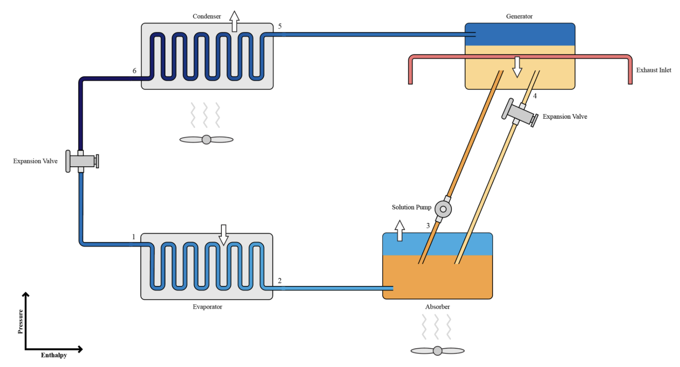
Figure 1. A labelled diagram of the absorption cooling system.
2.1. Point 1
The liquid, low-pressure, and low-specific enthalpy ammonia enters the evaporator, where it is evaporated inside the coils of the evaporator. Because evaporation is an endothermic process, it absorbs heat from its surroundings and produces a cooling effect.
2.2. Point 2
The ammonia vapour travels to the absorber.
2.3. Point 3
The ammonia vapour enters the absorber, which is filled with a low concentration ammonia solution (NH3 + H2O). The ammonia vapour is absorbed into water, causing the temperature of the absorber to gradually increase as absorption is an exothermic process. The increase in temperature decreases the water’s ability to absorb ammonia[citation]; hence, the absorber is cooled with the circulation of ambient air so that it can continuously absorb ammonia.
After absorption, the now strong solution is pumped using a solution pump, causing it to increase in pressure and specific enthalpy. Unlike gases which are compressible, liquids cannot be compressed and thus do not require as much shaft power when pumped because there is no work done. However, heat is required in the desorption of ammonia in the generator.
2.4. Point 4
The strong solution enters the generator, where thermal energy from vehicle exhaust provided through the exhaust inlet desorbs the ammonia from the water through evaporation. The boiling point of ammonia is lower than that of water, therefore only ammonia is freed as vapour. The ammonia vapour travels to the condenser. The now weak solution travels back to the absorber via an expansion valve that decreases its pressure.
2.5. Point 5
The high-pressure, high-specific enthalpy ammonia vapour enters the condenser. The condenser is water cooled and condenses the ammonia vapour into liquid ammonia, expelling heat as it is an exothermic process.
2.6. Point 6
The liquid ammonia travels back to the evaporator via an expansion valve that decreases its pressure. The cycle continues as the low-pressure and low-specific enthalpy ammonia reaches the evaporator.
3. Simulation model
All expressions in the form of \( f(x) \) below are calculated using the NIST REFPROP 9.1 thermodynamic property database. With reference to S. Manu and T.K. Chandrashekar’s absorption heat pump simulation model (2016) [7].
3.1. Provided parameters
Mass flow rate \( kg{s^{-1}} \)
\( Flowrate \)
Exhaust temperature \( K \)
\( Theating \)
Ambient air temperature \( K \)
\( Tair \)
Desired indoor temperature \( K \)
\( Tindoor \)
Heat transfer temperature difference \( ΔK \)
\( dT \)
Weak (low ammonia concentration) solution concentration \( \% \)
\( X4 \)
Strong (high ammonia concentration) solution concentration \( \% \)
\( X3 \)
3.2. Calculated parameters
Temperature leaving condenser \( K \)
\( T6=Tair+dT \)
The condenser temperature must be higher than the surrounding temperature for heat transfer to take place.
Temperature at generator \( K \)
\( T5=Theating-dT \)
\( T4=T5 \)
The generator temperature must be lower than the exhaust heat temperature for heat transfer to take place.
Temperature at absorber \( K \)
\( T3=Tair+dT \)
The absorber temperature must be higher than the surrounding temperature for heat transfer to take place.
Temperature leaving evaporator \( K \)
\( T2=Tindoor-dT \)
The evaporator temperature must be lower than the indoor temperature for heat transfer to take place.
Pressure at high pressure components (generator, leaving condenser) \( kPa \)
\( P6=f(T9,Q=0,ammonia) \)
\( P5=P6 \)
\( P4=P6 \)
The pressure of the generator and condenser can be calculated using the condenser temperature and the vapour fraction of ammonia, 0.
Pressure at low pressure components (evaporator, absorber) \( kPa \)
\( P2=f(T2,Q=1,ammonia) \)
\( P3=P2 \)
The pressure of the evaporator and absorber can be calculated using the evaporator temperature and the vapour fraction of ammonia, 1.
Specific enthalpy leaving evaporator \( kJk{g^{-1}} \)
\( H2=f(T2,Q=1,ammonia) \)
The specific enthalpy of the ammonia gas leaving the evaporator can be calculated using the evaporator temperature and its vapour fraction, 1.
Specific enthalpy of strong solution at absorber \( kJk{g^{-1}} \)
\( H3=f(T3,P3,X3\% ammonia (1-X3)\% water) \)
The specific enthalpy of the weak (before absorption) solution can be calculated using its temperature, pressure, and known ammonia to water ratio.
Specific enthalpy of weak solution at absorber \( kJk{g^{-1}} \)
\( H4=f(T4,P4,X4\% ammonia (1-X4)\% water) \)
The specific enthalpy of the strong (after absorption) solution can be calculated using its temperature, pressure, and known ammonia to water ratio.
Specific enthalpy of ammonia leaving generator \( kJk{g^{-1}} \)
\( H5=f(T5,P5,ammonia) \)
The specific enthalpy of the ammonia gas leaving the generator can be calculated using the temperature and pressure at the generator.
Specific enthalpy of ammonia leaving condenser \( kJk{g^{-1}} \)
\( H6=f(T6,Q=0,ammonia) \)
\( H1=H6 \)
The specific enthalpy of the liquid ammonia can be calculated using the temperature at the condenser and its vapour fraction after leaving the condenser, 0.
Flow rate of weak solution \( kg{s^{-1}} \)
\( M4=\frac{Flowrate-Flowrate\cdot X3}{X3-X4} \)
The flow rate of ammonia that functions as the refrigerant is equal to the amount that is desorbed from the strong solution. This amount is the difference between the strong and weak solutions’ ammonia content, hence \( M3\cdot X3-M4\cdot X4=Flowrate \) .
Likewise, the mass flow rate of the strong solution equals to the mass flow rate of the weak solution plus the mass flow rate of the ammonia that functions as the refrigerant, hence \( M3=M4+Flowrate \) .
Substituting \( M3=M4+Flowrate \) into the first equation:
\( X3(Flowrate+M4)-M4\cdot X4=Flowrate \)
\( Flowrate\cdot X3+M4\cdot X3-M4\cdot X4=Flowrate \)
\( M4\cdot X3-M4\cdot X4=Flowrate-Flowrate\cdot X3 \)
\( M4(X3-X4)=Flowrate-Flowrate\cdot X3 \)
\( M4=\frac{Flowrate-Flowrate\cdot X3}{X3-X4} \)
Flow rate of strong solution \( kg{s^{-1}} \)
\( M3=Flowrate+M4 \)
Cooling capacity \( W \)
\( Qcooling=Flowrate\cdot (H2-H1) \)
The cooling capacity of the system is the difference of the total thermal energy between points 2 and 1, located on either side of the evaporator which produces cooling. It is calculated by multiplying the specific enthalpy difference between the points H2 and H1 by the flow rate of ammonia, the refrigerant.
Heating requirement \( W \)
\( Qheating=(Flowrate\cdot H5)+(M4\cdot H4)-(M3\cdot H3) \)
The heating requirement of the system is the difference between the total thermal energy output and input at the generator. \( (Flowrate\cdot H5) \) is the thermal energy in the ammonia gas that is discharged into the condenser, \( (M4\cdot H4) \) is the thermal energy in the weak solution that flows back into the absorber via the expansion valve, and \( (M3\cdot H3) \) is the sole source of thermal energy input from the strong solution. Therefore, \( (Flowrate\cdot H5)+(M4\cdot H4)-(M3\cdot H3) W \) is required to desorb the ammonia from the strong solution in the generator.
Coefficient of Performance
\( COP=\frac{Qcooling}{Qheating} \)
The coefficient of performance is the ratio between the system’s cooling capacity and heating requirement needed.
3.3. Simulation flowchart
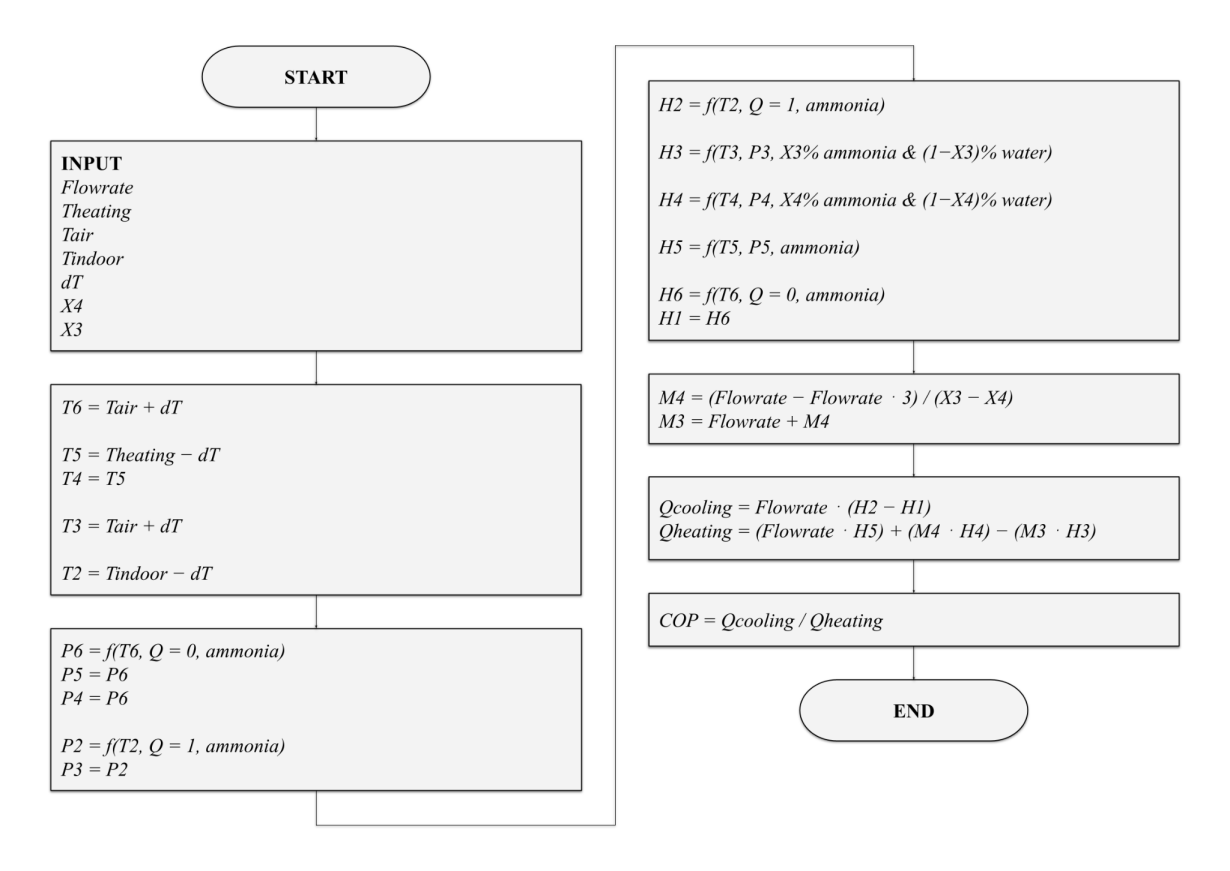
Figure 2. A flowchart detailing the calculations undergone in the mathematical model.
4. Experimental facility designation
4.1. Description
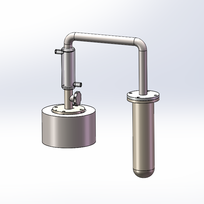
3) 4)
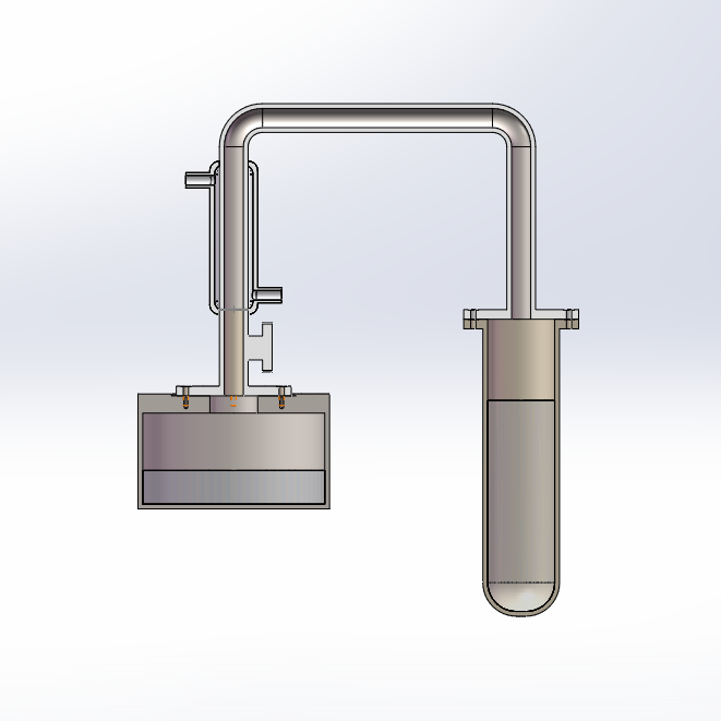
Figures 3 & 4. A model of the experimental facility, in regular and sectional view.
A simplified experimental facility, designed on the basis of the above absorption refrigeration system, was created to test its cooling effectiveness and efficiency. It is a hybrid system that is reversed to allow for both cooling (evaporation) and regeneration (condensation) modes.
From left to right as shown in Figures 3 & 4, the system consists of a water tank, control valve, condenser tube, connection pipe, and desiccant container. Additionally, a water circulation pump, pipes, and external reservoir are connected to the condenser tube, a vacuum pump is used to suck out any air in the system as preparation, and a boiling device (or boiling water in a container) is used to heat the desiccant container during regeneration.
The tank on the left side is injected with liquid water and functions as the evaporator. The condenser tube above the tank and control valve is water cooled and allows for the condensation of water vapour during regeneration. The tube on the right side is filled with desiccant (silica gel) and functions as both the absorber and generator, depending on the stage of the procedure.
4.2. Procedure
Preparation
1. Inject room temperature liquid water into the water tank through the opening. Seal the opening with a vacuum clamp and o-ring afterward.
2. Open the control valve. (This step refers to the valve above the water tank. The valve above the desiccant container remains open throughout the experiment and is only closed during storage.)
3. Connect the vacuum pump to the one-way valve and ensure the entire system is airtight.
4. Turn on the vacuum pump and vacuum the system to reduce its air pressure to the minimum.
5. Disconnect the vacuum pump from the one-way valve; the system remains in a vacuum state.
6. If not continuing with the experiment right away, close the control valve. Otherwise, continue onwards to the experimental procedure.
Experimental Procedure
Cooling/evaporation mode:
1. Open the control valve.
The liquid water starts evaporating and produces cooling.
The water vapour travels through the connection tube to the desiccant contained and is absorbed in the desiccant. Its partial pressure is lowered in the process.
Regeneration/condensation mode:
2. Submerge the desiccant container in boiling water so that it is at least level with the desiccant.
3. Turn on the circulation pump and ensure water is circulated through the condenser tube and water reservoir.
Water vapour is desorbed from the desiccant in the desiccant container and travels back through the connection tube.
Once the water vapour reaches the water cooled condenser tube, heat transfer occurs between the hot water vapour and cold circulated water.
Water vapour condenses and falls back into the water tank as liquid water.
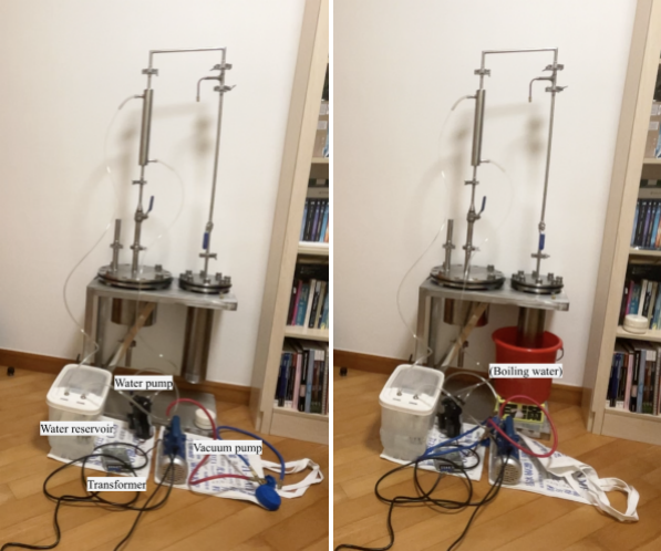
5) 6)
Figure 5 & 6. Images of the experimental facility, in cooling and regeneration modes.
5. Result analysis and optimisation
The following section will involve the analysis of two parameters involved in the simulation: the concentration ratio between the weak and strong (low and high ammonia to water ratio) solution, and the indoor, outdoor, and ambient temperatures. Changes to these parameters are reflected in the system’s coefficient of performance (COP), which is determined by the ratio between the cooling capacity (Qcooling) and heating requirement (Qheating, maximum 25,000 W) of the absorption refrigeration system. The simulation described in part III was used to conduct these tests.
5.1. Concentration ratio between weak and strong solutions
The weak solution concentration (X4) value was changed throughout the course of this test. Ammonia concentrations from 0.00 to 0.50 were tested in increments of 0.05, with the mass flow rate set to 0.0115 kg/s to satisfy the exhaust heat constraint of 25,000 W. The indoor temperature was set to 293 K (20°C), ambient air temperature to 308 K (35°C), and the heat transfer temperature to Δ5 K (Δ5°C). Results were recorded with varying strong solution concentration (X3) values, between 0.40, 0.45, and 0.50. The temperature of provided exhaust heat was then changed, with a range of 343 K (70°C), 353 K (80°C), and 363 K (90°C). The following charts show the correlation between the concentrations of the ammonia-water solutions and the coefficient of performance.
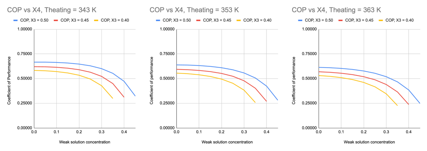
Figure 7. Relationship between weak solution concentration and coefficient of performance, at strong solution concentrations of 0.50, 0.45, and 0.40, and exhaust temperatures of 343 K, 353 K, and 363 K.
There is a negative correlation between the weak solution concentration (X4) and COP, and a positive correlation between the strong solution concentration (X3) and COP. This relationship can be generalised as a positive correlation between the difference between strong and weak solution concentration (ΔX) and COP. This prediction is scientifically sound because the amount of ammonia absorbed and transferred to the generator increases as the difference between strong and weak solution concentration increases. Therefore, the heating requirement decreases because there is less solution that needs to be heated in the generator.
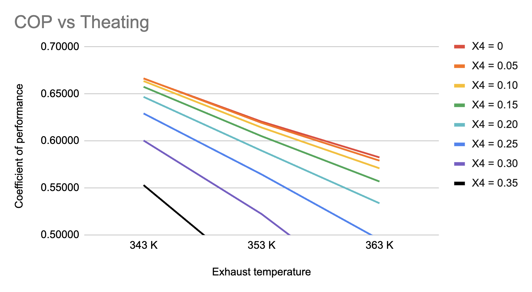
Figure 8. Relationship between exhaust temperature and coefficient of performance, at weak solution concentrations of 0 to 0.35 in increments of 0.05.
The weak solution concentration must also be capped at 0.35. The cooling capacity was constant throughout the trials at 12,493 W, while the maximum heat provided to the system was determined to be 25,000 W. This implies that any combination of the parameters above that results in a COP of less than 0.5 must have exceeded the threshold for maximum heat supplied to the system, and would not function if the heat supply fell below 25,000W. At X4 = 0.40 and any subsequent values, this threshold is passed and the system will not work.
It is seemingly counterintuitive that the COP decreases as the exhaust temperature increases. However, this phenomenon is explained by the simulation’s calculation process: when the heating requirement is fulfilled, any exceedingly high temperatures will only increase the heating requirement and not the cooling capacity. The temperature of the generator is equal to \( Theating-dT \) , and is used to calculate the ammonia’s specific enthalpy at the generator. As \( Qheating=(Flowrate\cdot H5)+(M4\cdot H4)-(M3\cdot H3) \) , it will increase because \( (M4\cdot H4) \) increases, thereby decreasing the COP.
5.2. Indoor, outdoor, and ambient temperatures
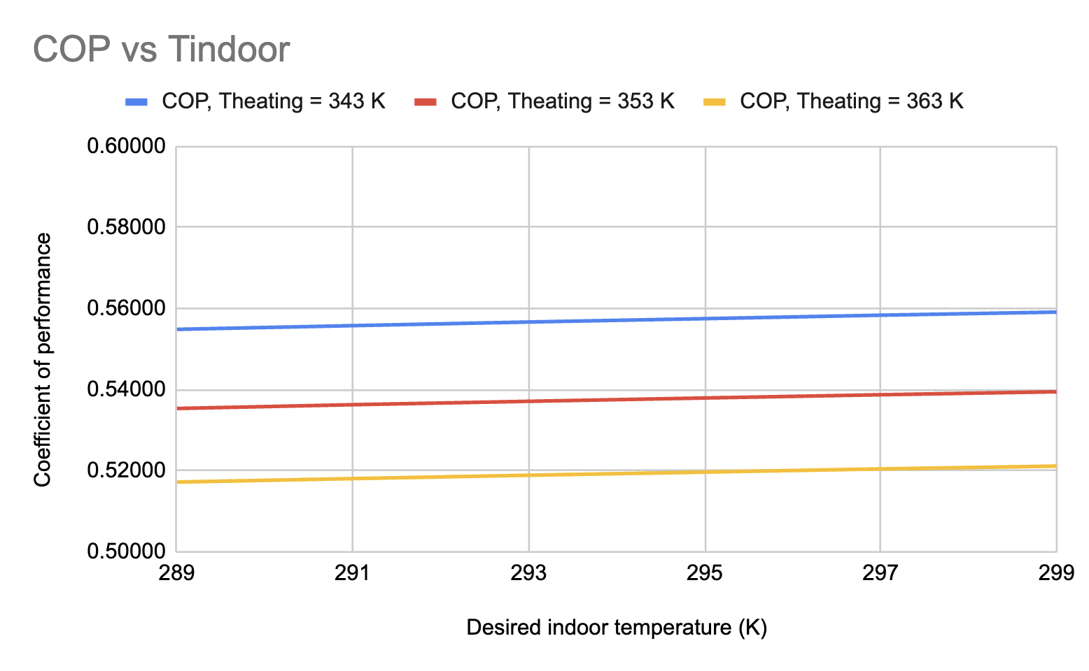
Figure 9. Relationship between desired indoor temperature (16 - 26°C) and coefficient of performance, at exhaust temperatures of 343 K (70°C), 353 K (80°C), and 363 K (90°C).
It is seen that the desired indoor temperature correlates positively with COP while exhaust temperature correlates negatively with COP (which was already explained). Because \( T2=Tindoor-dT \) and \( P2=f(T2,Q=1,ammonia) \) , the inlet pressure at the absorber increases as the desired indoor temperature increases. This means that there is less energy expenditure during the pumping process, resulting in a lower heating requirement value. Also, since \( Qcooling=Flowrate\cdot (H2-H1) \) , an increase in the H2 value (which is determined by T2) will also increase the cooling capacity. Therefore, the positive relationship between the desired indoor temperature and COP is justified.
5.3. Summary
To sum up the above section, the coefficient of performance is the highest when the difference between the concentrations of the strong and weak solutions are maximised, the indoor temperature is relatively high, and the exhaust temperature is relatively low.
There are several constraints on this trend, however. The weak solution concentration has a lower limit because 0 implies that there is no ammonia originally in the absorber, causing problems as it is difficult to ensure a satisfactory amount is desorbed in the generator before flowing back into the absorber as the ‘weak solution’. The strong solution has an upper limit as the solution may become completely saturated before all ammonia is used up: a saturated ammonia solution at 15.6°C contains 35.6% of ammonia by mass, meaning that the highest X3 value should only be 0.356 at that temperature [8].
Temperature wise, the simulation results correlate with past scientific findings that air conditioners are the most energy saving when set to 24-26°C [9]. There is no concern for controlling the exhaust temperature because it is sufficient for the absorption refrigeration system to function and higher temperatures do not negatively impact the cooling capacity. Nonetheless, there is potential for investigating the relationship between provided exhaust temperatures and COP at larger, industrial scales to ensure efficiency and minimise the thermal energy wasted through car exhaust.
6. Conclusion
The project investigates the feasibility of an absorption refrigeration air conditioning system to be installed in vehicles. An absorption refrigeration cycle using ammonia as the refrigerant and water as the absorbent was designed, and a mathematical model simulating its working process under different conditions was created. Tests conducted using the mathematical model drew a positive correlation between the difference in concentration between the strong and weak solutions and the COP of the system, with the weak solution concentration ranging from 0.00-0.35 in increments of 0.05 and the strong solution concentration at 0.40, 0.45, and 0.50. There is a negative correlation between vehicle exhaust temperatures of 343 K (70°C), 353 K (80°C), and 363 K (90°C) and the COP. There is a positive correlation between desired indoor temperatures of 289-299 K (16 - 26°C) in increments of 2 K (2°C) and the COP. A hybrid system experimental facility was designed and constructed. The cooling (evaporation) and regeneration (condensation) modes were tested using water and proved to be successful, verifying the efficacy of the designed absorption refrigeration air conditioning system. There is potential for further investigation into large-scale absorption refrigeration systems to minimise the energy wasted through exhaust, as the current system only uses a small fraction of the thermal energy supplied by the exhaust. In conclusion, theoretical and experimental investigations show that the absorption air conditioning system is able to produce cooling at reasonable efficiency with negligible operational costs, serving as a feasible option for vehicle owners to reduce their fuel expenditure and contribute to Hong Kong’s Climate Action 2050 goal.
References
[1]. Environment and Ecology Bureau. (2021). Hong Kong’s Climate Action Plan 2050. [online] Available at: www.eeb.gov.hk/sites/default/files/pdf/cap_2050_en.pdf.
[2]. HK Electric. (2023). HK Electric 2023 Tariff Adjustments. [online] Available at: www.hkelectric.com/en/media/press-releases/year-2022/hk-electric-2023-tariff-adjustments.
[3]. Electrical and Mechanical Services Department. (2022). Hong Kong Energy End-use Data. [online] Available at: www.emsd.gov.hk/filemanager/en/content_762/HKEEUD2022.pdf.
[4]. J.D. Power. (2022). What Is The Average Horsepower Of A Car? [online] Available at: www.jdpower.com/cars/shopping-guides/what-is-the-average-horsepower-of-a-car.
[5]. Barba, Daniel. (2018). Assessing the Efficiency Potential of Future Gasoline Engines. [online] Available at: www.epa.gov/sites/default/files/2018-10/documents/high-efficiency-ic-engine-sae-2018-04.pdf.
[6]. HK Electric. (2022). Estimated Consumption Units of Common Appliances. [online] Available at: www.hkelectric.com/en/customer-services/billing-payment-and-tariffs/bill/Estimated-Consumption-Units-of-Common-Appliances.
[7]. Manu, S., Chandrashekar, T.K.. (2016). A simulation study on performance evaluation of single-stage LiBr–H2O vapor absorption heat pump for chip cooling. [online] Available at: https://www.sciencedirect.com/science/article/pii/S2212609016300401.
[8]. Appl, Max. (2006). Ammonia, Ullmann’s Encyclopedia of Industrial Chemistry. ISBN 978-3527306732.
[9]. Electrical and Mechanical Services Department. (2023). Energy Saving Tips For Home. [online] Available at: www.emsd.gov.hk/energyland/en/tips/home/air_conditioner.html.
Cite this article
Liu,Z. (2024). Development and analysis of a practical absorption air conditioning system employing waste heat recovered from vehicle exhaust. Applied and Computational Engineering,65,193-203.
Data availability
The datasets used and/or analyzed during the current study will be available from the authors upon reasonable request.
Disclaimer/Publisher's Note
The statements, opinions and data contained in all publications are solely those of the individual author(s) and contributor(s) and not of EWA Publishing and/or the editor(s). EWA Publishing and/or the editor(s) disclaim responsibility for any injury to people or property resulting from any ideas, methods, instructions or products referred to in the content.
About volume
Volume title: Proceedings of Urban Intelligence: Machine Learning in Smart City Solutions - CONFSEML 2024
© 2024 by the author(s). Licensee EWA Publishing, Oxford, UK. This article is an open access article distributed under the terms and
conditions of the Creative Commons Attribution (CC BY) license. Authors who
publish this series agree to the following terms:
1. Authors retain copyright and grant the series right of first publication with the work simultaneously licensed under a Creative Commons
Attribution License that allows others to share the work with an acknowledgment of the work's authorship and initial publication in this
series.
2. Authors are able to enter into separate, additional contractual arrangements for the non-exclusive distribution of the series's published
version of the work (e.g., post it to an institutional repository or publish it in a book), with an acknowledgment of its initial
publication in this series.
3. Authors are permitted and encouraged to post their work online (e.g., in institutional repositories or on their website) prior to and
during the submission process, as it can lead to productive exchanges, as well as earlier and greater citation of published work (See
Open access policy for details).
References
[1]. Environment and Ecology Bureau. (2021). Hong Kong’s Climate Action Plan 2050. [online] Available at: www.eeb.gov.hk/sites/default/files/pdf/cap_2050_en.pdf.
[2]. HK Electric. (2023). HK Electric 2023 Tariff Adjustments. [online] Available at: www.hkelectric.com/en/media/press-releases/year-2022/hk-electric-2023-tariff-adjustments.
[3]. Electrical and Mechanical Services Department. (2022). Hong Kong Energy End-use Data. [online] Available at: www.emsd.gov.hk/filemanager/en/content_762/HKEEUD2022.pdf.
[4]. J.D. Power. (2022). What Is The Average Horsepower Of A Car? [online] Available at: www.jdpower.com/cars/shopping-guides/what-is-the-average-horsepower-of-a-car.
[5]. Barba, Daniel. (2018). Assessing the Efficiency Potential of Future Gasoline Engines. [online] Available at: www.epa.gov/sites/default/files/2018-10/documents/high-efficiency-ic-engine-sae-2018-04.pdf.
[6]. HK Electric. (2022). Estimated Consumption Units of Common Appliances. [online] Available at: www.hkelectric.com/en/customer-services/billing-payment-and-tariffs/bill/Estimated-Consumption-Units-of-Common-Appliances.
[7]. Manu, S., Chandrashekar, T.K.. (2016). A simulation study on performance evaluation of single-stage LiBr–H2O vapor absorption heat pump for chip cooling. [online] Available at: https://www.sciencedirect.com/science/article/pii/S2212609016300401.
[8]. Appl, Max. (2006). Ammonia, Ullmann’s Encyclopedia of Industrial Chemistry. ISBN 978-3527306732.
[9]. Electrical and Mechanical Services Department. (2023). Energy Saving Tips For Home. [online] Available at: www.emsd.gov.hk/energyland/en/tips/home/air_conditioner.html.