


1. Introduction
The reliability of electrified railway operation depends on the reliability of traction power supply equipment, so the operational status of the catenary system has very high requirements. The existing catenary suspension types can be roughly divided into simple suspension, elastic simple suspension, and chain suspension. In order to increase the support device distance, save costs, reduce wear of contact parts, and make the elasticity of the contact line more uniform, the current commonly used structure is the chain suspension overhead contact system.
The purpose of the tension compensation device is to compensate for the influence of tension on the conductor when the temperature changes, so that the tension of the conductor is basically constant, thereby ensuring that the sag of the conductor is within the allowable range. Full compensation means that both the supporting cable and the contact wire are equipped with compensation devices. During actual operation, if the tension compensation device is in abnormal working condition, it may lead to abnormal tension of the compensated conductor, damage to components, abnormal parameters of the contact wire system, and deterioration of the pantograph-wire relationship. More seriously, it may cause overhead catenary system accidents. Therefore, maintaining the working parameters of the tension compensation device within the normal range is crucial for the contact wire. Daily inspection of the tension compensation device is also a key focus for railway operation departments.
The monitoring of the working status of the contact wire tension compensation device has not been addressed. In this project, a mobile contact wire tension compensation device status detection system is proposed and can be installed on inspection trains for regular and timely monitoring of the working status of the tension compensation device.
2. Tension Compensation Device Status Detection Research
2.1. Research background
The types of tension compensation devices include ratchet/pulley group tension compensation devices, hydraulic tension compensation devices, electromechanical tension compensation devices, and spring tension compensation devices. Among them, the hydraulic tension compensation device is only suitable for length changes caused by environmental temperature changes; the electromechanical tension compensation device, although adjustable in its limit value, requires a reliable power supply; the spring tension compensation device is often used in short compensation sections of urban rail transit, not on mainline railways. The ratchet/pulley tension compensation device has mature technology, wide application, and is widely used in the railway system, especially in high-speed railways. The tension compensation device state detection technology proposed in this article is designed for this type of compensation device.
2.2. Research status of tension compensation device state detection technology
The design and construction installation technology of the overhead contact system in our country continues to improve, reaching the world’s leading level in high-speed rail technology. However, the development of the state detection technology for the tension compensation device has been relatively slow. Currently, the maintenance method for the electrified railway overhead contact system in our country mainly follows the “Overhead Contact System Operation and Maintenance Regulations”. The monitoring items in the regulations only focus on whether the compensating device is damaged, whether it operates flexibly, whether the supporting positioning device is normal, and other aspects. The inspection method mainly relies on visual inspection, which consumes a large amount of manpower and resources and has low efficiency. Therefore, relevant scholars have proposed research on monitoring technology for the compensating device.
The literature [1-2] designed an online monitoring system that uses a laser sensor to real-time monitor the compensation device value, which refers to the distance between the lowest point of the plumb bob and the ground, as shown in Figure 1. This value is directly related to the environmental temperature and tension, so the monitored value can achieve real-time monitoring of the tension of the anchorage section. Building on this research, literature [3-5] proposed an online monitoring device for high-speed railway catenary compensation devices. By using ultrasonic sensors to monitor the compensation value of the contact line and the load-bearing cable, the cost of sensors is reduced. In addition, the system combines an analysis of environmental temperature to determine if the tension compensation device is working properly. Furthermore, literature [6] analyzed the safety impact of tension on the catenary and proposed the installation of an accelerometer sensor on the compensation plumb bob. The longitudinal vibration acceleration of the catenary line tension is analyzed and processed by the ARM management system. Literature [7] monitored the transmission efficiency of the ratchet compensation device by installing a deflection angle measurement module on the ratchet. Literature [8] installed tension sensors at the connection between the ratchet and the contact line and load-bearing cable. The proposed online measurement system for contact wire tension can real-time monitor the tension of the contact line and load-bearing cable, achieving the goal of preventing contact wire accidents. Finally, literature [9] combined ultrasonic sensor measurements and tension sensor methods to comprehensively assess the working status of the contact wire, providing early warning for jamming and wire breakage situations. Additionally, practical cases demonstrated the reliability and stability of this approach.
The technical solutions proposed in references [1-7] can monitor the changes in the compensation weight or vibration of the tension compensation device fairly well. However, they cannot effectively monitor the changes in the contact wire tension on the operational line, which may result in the tension on the line not matching the gravity provided by the compensation weight due to the rusting or jamming of the ratchet. On the other hand, references [8-9] involve installing tension sensors at the connection point between the ratchet and the transmission lines. Although this type of solution can better monitor changes in contact wire tension, the use of sensors to some extent reduces the reliability of the contact wire system, increases the likelihood of wire breakage, and raises the difficulty of maintenance and replacement of components.

Figure 1. Schematic Diagram of Tension Compensation Device
This article proposes a state detection system for a vehicle-mounted catenary tension compensation device, which is installed on an inspection train to facilitate the measurement of contact line tension without the need for structural modification of the contact network system.
2.3. Method for monitoring line tension
Currently, there are several methods for monitoring the tension of overhead contact line internationally and domestically, such as sensor connection method, sag-tension conversion method, three-point bending method, electromagnetic wave detection method, and other detection methods.
The sensor connection method refers to directly connecting force sensors to the contact wire. However, this method has great limitations and is therefore not considered here. The sag-tension conversion method indirectly calculates the tension of the contact line through the sag of the wire, and this method is highly susceptible to external factors, leading to a high error rate [10]. Electromagnetic wave detection utilizes the propagation cycle of electromagnetic waves on the steel wire to calculate the tension of the wire. However, this method is not suitable for monitoring the tension of the contact wire due to the high voltage carried by the contact line [11-13], which can interfere with the transmission of electromagnetic waves and the normal operation of sensors. On the other hand, the three-point bending method forces the contact wire to produce local deformation similar to three-point bending using three points on the sensor, thereby indirectly measuring the tension of the contact wire [14-18]. This paper will focus on using this method to propose the design of the device.
3. On-board tension compensation device status detection system overall design
3.1. Three-point bending method
The three-point bending method applies a certain lateral force to a local area of the cable to produce local deformation similar to three-point bending, as shown in the figure below.
When measuring tension, points A and B are fixed points, and point C is the center of action that simultaneously generates displacement signals and receives reaction forces. The lateral distance between the two fixed points at the ends of the three-point bending device and the center of action point is the tension angle. The force applied to the cable is shown in figure 2, from which the relationship between cable tension and angle can be obtained.
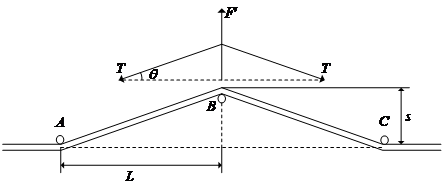
Figure 2. Schematic diagram for calculating the tension of the normal force in the three-point bending method
From the force analysis, it can be known that there is tension between the clues.
\( F=2Tsin{θ}\ \ \ (1) \)
the value of θ is:
\( sin{θ}=\frac{L}{\sqrt[]{{L^{2}}+{s^{2}}}}\ \ \ (2) \)
The relationship between line tension and horizontal distance, lateral displacement, and acting force can be known from the above equation.
\( T=\frac{F\sqrt[]{{L^{2}}+{s^{2}}}}{2s}\ \ \ (3) \)
3.2. Overall system design
The status detection system of the vehicle-mounted contact net tension compensation device designed in this article mainly includes the sensor unit, data acquisition unit, control unit, data processing and analysis unit, and human-machine interface.

Figure 3. System composition diagram
The main functions of each part are as follows:
Sensor unit: used to monitor the state and parameters of the catenary tension compensation device. It should include tension sensors for measuring catenary tension, position sensors for measuring device position, and acceleration sensors at the end of the falling weight to obtain different state information. The sensor at the end of the falling weight should also be equipped with a GPRS module.
Data acquisition unit: responsible for collecting data generated by sensors and processing and integrating it. The data acquisition unit samples sensor data, and stores and transmits the data.
Control positioning unit: used to control, adjust, and position the mechanical arm on the inspection train to align with the catenary. The control unit is operated by the operator through the human-machine interface.
Data processing and analysis unit: responsible for processing and analyzing the collected data. This unit can use algorithms and models to extract the tension of the line-side mechanical arm and compare the acceleration sensor data sent by the falling weight during the same period. It analyzes whether there is rust or sticking in the tension compensation device, provides whether the tension is within the normal range, and so on.
Human-machine interface: used to operate and monitor the system. The human-machine interface can be a display screen, control panel, or computer interface, allowing operators to view status information, set parameters, and control the system.
During the inspection of the inspection train, the operator stops the train under the contact wire, first uses the human-machine interface to operate the control positioning unit to lift the sensor unit on the inspection train to above the wire, fix the wire at the fixed point, and use the center force point to make the wire appear as a three-point bend. The sensor parameters are input to the data acquisition unit; at the same time, the data acquisition unit collects the data at the tension compensation device of this section through the GPRS module; the data acquisition unit then inputs the collected data to the data processing and analysis unit, and the results are returned to the human-machine interface through analysis.

Figure 4. Schematic for measuring contact wire tension using the three-point bending method
4. Existing issues
(1) The risk of damaging the contact wire is addressed. The three-point bending method used in this paper applies a certain force to the wire and measures this force to derive the tension within the wire. During this process, the measuring instrument should comply with the characteristics and specifications of the contact wire to avoid causing significant damage.
(2) There is still room for improvement in detection efficiency. The state detection device of the vehicle-mounted contact wire tension compensator proposed in this paper can only measure intermittently. While its detection efficiency and reliability are higher than manual inspections, it cannot detect continuously with the forward movement of the inspection vehicle. Subsequent research should focus on improving detection efficiency.
(3) The accuracy of the measurements still needs to be improved. The system proposed in this paper mainly utilizes the three-point bending method for wire tension detection. Relevant literature indicates that the larger the tension angle produced during detection, the higher the testing accuracy; conversely, smaller tension angles will lead to greater errors. However, excessively large tension angles will increase wire wear. Therefore, future research should focus on balancing the accuracy of detection with the degree of wire wear during testing.
5. Conclusions
This paper comprehensively analyzed the existing tension compensation device status detection technology and found some shortcomings. In order to address these issues, we proposed a tension compensation device status detection system based on the three-point bending method and b-value monitoring for the on-board overhead contact line. This system can monitor the working status of the tension compensation device simultaneously at the line side and the anchorage section end, and can issue timely abnormal warnings, having significant practical value.
By implementing this system, the railway operating department can immediately take necessary maintenance and adjustment measures when the tension compensation device’s working status is abnormal, to ensure the normal operation of the overhead contact line system. In addition, the system also provides operating personnel with a more comprehensive status monitoring and fault diagnosis tool for better maintenance and management of the overhead contact line system.
In conclusion, the on-board contact net tension compensation device status detection system proposed in this study provides a reliable method for monitoring the working status of the contact net device, and it has important practicality and application potential in preventing and addressing device abnormalities. Future research can further optimize the performance and reliability of this system to meet the constantly changing operational needs of railways, and explore other possible monitoring technologies and methods to enhance the safety and reliability of the contact net system.
References
[1]. Zhao Xiuyuan. Research on Contact Network Compensator B-Value Online Monitoring System [J]. Science and Technology Information, 2016, 14(34): 48-49.J. Clerk Maxwell, A Treatise on Electricity and Magnetism, 3rd ed., vol. 2. Oxford: Clarendon, 1892, pp.68-73.
[2]. Li Xiaoxu. Research on Online Detection Device for Compensator B-Value of Overloaded Railway Contact Network [J]. Electrified Railway, 2022, 33(S1): 121-124+128.
[3]. Bai Bochun. Design Research on High-speed Railway Contact Network Compensator Online Monitoring System [D]. Shijiazhuang Tiedao University, 2013.
[4]. Liu Kun. Research on Tension Automatic Compensator Online Monitoring System and Data Analysis [D]. Shijiazhuang Tiedao University, 2015.
[5]. Zhang Zhipeng. Development of Contact Network Compensator Online Monitoring System [D]. Beijing Jiaotong University, 2018.
[6]. Li Xin. Design of Contact Network Safety State Online Monitoring System Based on Tension and Temperature [D]. Beijing Jiaotong University, 2015.
[7]. Deng Chao. Study on the Impact of Ratchet Deflection Angle on Contact Network Safety State and Online Monitoring System [D]. Beijing Jiaotong University, 2014.
[8]. Liu Huiping, Han Tongxin, Zhao Bosheng, Liu Yinqu. Research and Implementation of Contact Network Tension Online Measurement System [J]. Railway Locomotive & Car, 2016, 36(01): 49-51.
[9]. Tan Ping, Qiu Liangjie, Ding Jin, Lin Jian, Li Zengqin, Huang Wenjun. Research on Key Parameter Monitoring Technology of High-speed Railway Contact Network Anchor Section Termination [J]. Instrument Technique and Sensor, 2023(02): 115-120.
[10]. Liu Hao. Tension Management of Overhead Contact Network Clues [D]. Southwest Jiaotong University, 2014.
[11]. Wang Qinxian, Li Honglei, Yang Zhaojian. Research on Tension Testing System of Multi-rope Hoist Wire Rope Based on Vibration Wave Method [J]. Industrial Automation, 2010, 36(08): 1-4.
[12]. Du Fan, Yang Zhaojian. Testing Method for Tension of Hoist Wire Rope Based on Non-uniform Cord Vibration [J]. Journal of China Coal Society, 2010, 35(05): 840-843.
[13]. Wang Qinxian, Yang Zhaojian. Research on Tension of Hoist Wire Rope by Vibration Wave Method [J]. Coal Mine Machinery, 1999(04): 17-19.
[14]. Li Chunjing, Tan Jiwen, Tian Jun. Research Status and Trend of Steel Wire Rope Tension Detection [J]. Coal Mine Safety, 2006(01): 53-55.
[15]. Yao Wenbin, Cheng Heming. Determination of Steel Wire Rope Tension by “Three-point Bending Method” Principle [J]. Experimental Mechanics, 1998(01): 80-85.
[16]. Chen Jianxun, Cui Daguang, Lin Xiaoming, Zhang Junhao, Tai Shenglin. Research on the Test Accuracy of Tension Deviation of Elevator Traction Steel Wire Rope by Three-point Bending Method [J]. China Special Equipment Safety, 2018, 34(04): 26-30+34.
[17]. Wu Weiwei. Design of Online Monitoring Scheme for Safe Operation of Contact Network [D]. Southwest Jiaotong University, 2017.
[18]. Chen Jianxun, Cui Daguang, Lin Xiaoming, Zhang Junhao, Tai Shenglin. Research on the Test Accuracy of Tension Deviation of Elevator Traction Steel Wire Rope by Three-point Bending Method [J]. China Special Equipment Safety, 2018, 34(04): 26-30+34.
Cite this article
Wang,X.;Ouyang,C. (2024). Design exploration of the status detection system for car-mounted catenary tension compensation device. Applied and Computational Engineering,65,260-266.
Data availability
The datasets used and/or analyzed during the current study will be available from the authors upon reasonable request.
Disclaimer/Publisher's Note
The statements, opinions and data contained in all publications are solely those of the individual author(s) and contributor(s) and not of EWA Publishing and/or the editor(s). EWA Publishing and/or the editor(s) disclaim responsibility for any injury to people or property resulting from any ideas, methods, instructions or products referred to in the content.
About volume
Volume title: Proceedings of Urban Intelligence: Machine Learning in Smart City Solutions - CONFSEML 2024
© 2024 by the author(s). Licensee EWA Publishing, Oxford, UK. This article is an open access article distributed under the terms and
conditions of the Creative Commons Attribution (CC BY) license. Authors who
publish this series agree to the following terms:
1. Authors retain copyright and grant the series right of first publication with the work simultaneously licensed under a Creative Commons
Attribution License that allows others to share the work with an acknowledgment of the work's authorship and initial publication in this
series.
2. Authors are able to enter into separate, additional contractual arrangements for the non-exclusive distribution of the series's published
version of the work (e.g., post it to an institutional repository or publish it in a book), with an acknowledgment of its initial
publication in this series.
3. Authors are permitted and encouraged to post their work online (e.g., in institutional repositories or on their website) prior to and
during the submission process, as it can lead to productive exchanges, as well as earlier and greater citation of published work (See
Open access policy for details).
References
[1]. Zhao Xiuyuan. Research on Contact Network Compensator B-Value Online Monitoring System [J]. Science and Technology Information, 2016, 14(34): 48-49.J. Clerk Maxwell, A Treatise on Electricity and Magnetism, 3rd ed., vol. 2. Oxford: Clarendon, 1892, pp.68-73.
[2]. Li Xiaoxu. Research on Online Detection Device for Compensator B-Value of Overloaded Railway Contact Network [J]. Electrified Railway, 2022, 33(S1): 121-124+128.
[3]. Bai Bochun. Design Research on High-speed Railway Contact Network Compensator Online Monitoring System [D]. Shijiazhuang Tiedao University, 2013.
[4]. Liu Kun. Research on Tension Automatic Compensator Online Monitoring System and Data Analysis [D]. Shijiazhuang Tiedao University, 2015.
[5]. Zhang Zhipeng. Development of Contact Network Compensator Online Monitoring System [D]. Beijing Jiaotong University, 2018.
[6]. Li Xin. Design of Contact Network Safety State Online Monitoring System Based on Tension and Temperature [D]. Beijing Jiaotong University, 2015.
[7]. Deng Chao. Study on the Impact of Ratchet Deflection Angle on Contact Network Safety State and Online Monitoring System [D]. Beijing Jiaotong University, 2014.
[8]. Liu Huiping, Han Tongxin, Zhao Bosheng, Liu Yinqu. Research and Implementation of Contact Network Tension Online Measurement System [J]. Railway Locomotive & Car, 2016, 36(01): 49-51.
[9]. Tan Ping, Qiu Liangjie, Ding Jin, Lin Jian, Li Zengqin, Huang Wenjun. Research on Key Parameter Monitoring Technology of High-speed Railway Contact Network Anchor Section Termination [J]. Instrument Technique and Sensor, 2023(02): 115-120.
[10]. Liu Hao. Tension Management of Overhead Contact Network Clues [D]. Southwest Jiaotong University, 2014.
[11]. Wang Qinxian, Li Honglei, Yang Zhaojian. Research on Tension Testing System of Multi-rope Hoist Wire Rope Based on Vibration Wave Method [J]. Industrial Automation, 2010, 36(08): 1-4.
[12]. Du Fan, Yang Zhaojian. Testing Method for Tension of Hoist Wire Rope Based on Non-uniform Cord Vibration [J]. Journal of China Coal Society, 2010, 35(05): 840-843.
[13]. Wang Qinxian, Yang Zhaojian. Research on Tension of Hoist Wire Rope by Vibration Wave Method [J]. Coal Mine Machinery, 1999(04): 17-19.
[14]. Li Chunjing, Tan Jiwen, Tian Jun. Research Status and Trend of Steel Wire Rope Tension Detection [J]. Coal Mine Safety, 2006(01): 53-55.
[15]. Yao Wenbin, Cheng Heming. Determination of Steel Wire Rope Tension by “Three-point Bending Method” Principle [J]. Experimental Mechanics, 1998(01): 80-85.
[16]. Chen Jianxun, Cui Daguang, Lin Xiaoming, Zhang Junhao, Tai Shenglin. Research on the Test Accuracy of Tension Deviation of Elevator Traction Steel Wire Rope by Three-point Bending Method [J]. China Special Equipment Safety, 2018, 34(04): 26-30+34.
[17]. Wu Weiwei. Design of Online Monitoring Scheme for Safe Operation of Contact Network [D]. Southwest Jiaotong University, 2017.
[18]. Chen Jianxun, Cui Daguang, Lin Xiaoming, Zhang Junhao, Tai Shenglin. Research on the Test Accuracy of Tension Deviation of Elevator Traction Steel Wire Rope by Three-point Bending Method [J]. China Special Equipment Safety, 2018, 34(04): 26-30+34.