


1. Introduction
This research aims to provide a design concept of an electric aircraft that can take off vertically and fly with a lift generated with a fixed wing on Mars. This concept improves on the advantage in terms of mobility from Ingenuity while maintaining the advantage of take-off and landing vertically, hence more suitable for the rough terrain on Mars. With this concept, the Martian aircraft is likely to far exceed the coverage of the Martian Surface by any previous rovers that have landed on Mars, unhindered by any existing obstacle for ground rovers. This promises better image quality of aerial views of Martian terrain, outperforming current optical satellites in Martian orbit, helping with more precise mapping of Mars’ complicated terrain. Another unique advantage of this aircraft is that it can conduct gas sampling at different desired altitudes, which has never been done in any previous missions [1].
To achieve such an outcome in the concept, several design challenges will need to be addressed. For aircraft to maintain level flight on Mars, its aerodynamic features need to be optimised for entirely different conditions compared to Earth. The choice of propulsion system is also crucial to the mission duration as it regards the availability of energy regeneration for power. Several other new technologies that were not applied before can also be used to contribute to the efficiency and versatility of the aircraft such as tilt-wing and distributed electric propulsion. This research also concerns the applications and constraints of the aircraft in the case of mission planning in later sections.
2. Analysis of Previous Concepts
There have been several concepts being developed surrounding the subject of flying on Mars. Other than the most notable one, Ingenuity, there also has been a concept Martian aircraft named Aerial Regional-scale Environmental Survey (ARES) being developed by NASA Langley Research Centre [2], as shown in Figure 1, aiming to be selected for the Mars Scout Mission. Despite the project not eventually coming to fruition, the project researchers have conducted a comprehensive development into a rocket-powered fixed-wing Martian aircraft which could serve as a great reference in our research. The mission aims to conduct a 500km survey while flying at an altitude lower than 2000 metres. The aircraft weighs around 100 kilograms and is deployed mid-air, after going through the extreme heat of atmospheric entry with its aeroshell. After jettisoning its heat shield, the aircraft is released with the deployment drogue at around 8000 metres above ground. The wing unfolds and the aircraft eventually levels out at above 2000 meters. The propulsion system consists of a bi-propellant 14 lbf engine powered by 48 kilograms of MMH (Mono-Methyl Hydrazine) and MON-3 (Nitrogen Tetroxide with a 3% Mixed Oxides of Nitrogen additive) fuel. Before Langley Research Centre stopped the development of the concept, the team successfully conducted a flight test with the prototype at high altitudes where the atmospheric condition resembles the Mars surface. The ARES mission concept inspires us with the idea of conducting scientific research by sustaining a powered flight in the Martian atmosphere, which otherwise cannot be done with traditional ground probes and rovers [3]. It also provides a reference for the design of this research by practising a systematic approach towards the designing of the aircraft based on the integration of mission requirements and engineering specifications, while maintaining a list of assessments of risks associated. Like ARES, the concept of the tilt-wing Martian aircraft in this research is formed by designing the aircraft which aims at accomplishing mission requirements whilst solving problems arising along.
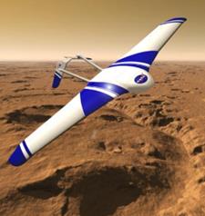
Figure 1. Rendering of ARES flying over Mars. ©NASA Langley Centre
3. Aircraft design – Lift and Drag
The most important requirement for an aircraft to sustain flight is to generate lift to balance its weight. When flying level, a tilt-wing aircraft generates lift with the same essential principle as a fixed-wing aircraft. The lift generated by a wing is given by the equation:
\( L\ =\ {\frac{1}{2}C}_LqS \) (1)
where L is the lifting force generated, \( C_L \) is the coefficient of lift, a property of the wing, S is the area of the wing and q is the dynamic pressure.
Dynamic pressure q is given by:
\( q\ =\ \frac{1}{2}\rho V^2 \) (2)
where \( \rho \) is the density of air around and V is the flowing speed.
The mean gravitational force on Mars’s surface is only 3.73 \( m/s^2 \) as opposed to 9.82 \( m/s^2 \) on Earth (Archive), hence the ratio between the weight of the aircraft on Mars and on Earth would be in a ratio of 0.380. Since an aircraft has its weight balanced by the lift generated from its wing in level flight, this ratio means that only 0.380 of lift force is required to keep an aircraft in a level flight on Mars compared to aircraft of same mass on Earth. However, the density of Mars atmosphere is also considerably thinner than Earth. The air density on Mars surface is only around 0.020 \( kg/m^3 \) compared to 1.293 \( kg/m^3 \) on Earth (NASA, Air Mass/Density - Earthdata - NASA, 2019), the ratio is less than 1/60. The combination of these two results leads to the conclusion that the product of dynamic pressure, coefficient of lift and wing area are required to be more than 20 times larger for an aircraft comparable on Earth to stay in level flight on Mars.
For such specification to be achieved, three factors need to be taken into consideration. flight speed, wing area and coefficient of lift. However, altering some of these properties would also lead to the change of drag generated by the aircraft. For the aircraft to stay in a level flight, the thrust provided by the propulsion system of the aircraft must balance the aerodynamic drag generated in flight. The drag of an aircraft is given by:
\( D\ =\ {\frac{1}{2}C}_DqS \) (3)
where D is drag generated, \( C_D \) is the coefficient of drag, a property of the wing, like \( C_L \) , S is the area of the wing and q is the dynamic pressure. For the definition of dynamic pressure, see above in the part regarding lift force. As can be noticed, the equation of lift and frag share the same term regarding the dynamic pressure and surface area of the wing. In this case, the lower air density of Mars is beneficial in terms of lowering dynamic pressure, hence the drag force generated. The presence of these two terms in both equations means by increasing the flying speed of the aircraft and wing area, the aircraft gains lift but requires much more power to maintain its speed. Hence, the best way to optimize flying performance is to obtain a maximum coefficient of lift and minimize the coefficient of drag while increasing the wing area. A measure of this performance is called the lift-to-drag ratio, which is the ratio between lift force and drag force generated by the wing, and therefore also the ratio between the wing’s coefficient of lift and coefficient of drag. To maximise the lift-to-drag ratio, several designing measures can be taken by looking into the make-up of the coefficient of lift and coefficient of drag.
The coefficient of Lift \( C_L \) is given by:
\( C_{L\ \ }=C_{L_0}+C_{L_\alpha}\alpha \) (4)
where \( C_{L_0} \) is the lift coefficient at zero angles of attack, \( C_{L_\alpha} \) is the lift coefficient slope concerning angle of attack and \( \alpha \) is the angle of attack. While the coefficient of lift at zero angle of attack is to do with the airfoil shape of the wing, the second term is a product between coefficient slope and the angle of attack. It is common knowledge on Earth that when an aircraft flies with an angle of attack higher than a certain value, known as the critical angle of attack, the airflow separates from the surface of the wing, causing a drastic reduction in lift and leading to a stall. Stall has been proven to be fatal in lots of accidents involving aircraft on Earth, and Mars is no exception in this. Given the complexity of recovering a damaged aircraft that fell out of the sky on Mars, increasing the angle of attack in flight may not be an ideal solution to increasing lift compared to optimizing the airfoil shape.
At the same time, reducing coefficient of drag also contributes to maximise lift to drag ratio. The coefficient of drag \( C_L \) is given by:
\( C_D=C_{D_{min}}+\ \frac{{C_L}^2}{\pi ARe} \) (5)
Where \( C_{D_{min}} \) is the minimum drag coefficient, \( AR \) is the aspect ratio and \( e\ \) is the Oswald efficiency factor. The minimum drag coefficient is determined by the wing shape as well as the smoothness of the wing surface, the drag related to these two properties of the wing are known as form drag and skin friction. In commercial airliners, the skin paint and rivets exposed outside can all affect this term. In the case of a Martian aircraft, the assembly technique can be made much simpler due to the nature of its small size, hence avoiding increasing drag. The induced drag which is represented with the second term is associated with the coefficient of lift, aspect ratio and the Oswald efficiency. While the coefficient cannot be reduced as it also affects lift, the aspect ratio and Oswald efficiency can be maximized to reduce induced drag. The aspect ratio is the square of the span divided by the wing area, hence a wing with a high aspect ratio is typically long and slender, commonly seen in gliders. The Oswald efficiency is related to the wing shape as it is equal to 1.0 for an elliptic distribution and is some value less than 1.0 for any other lift distribution [4].
With all the properties considered, it can be concluded that the airfoil as well as its wing shape would need to be optimised for the given air density on Mars. The lift force can also be increased with a large wing area while maintaining a low width to ensure a high aspect ratio to minimise drag generated. For aircraft designed to fly under such atmospheric conditions, several examples can be found that are aimed to fly at high altitudes on Earth. Martian aircraft operate on Mars at an atmospheric density equivalent to the atmosphere of Earth at 30 to 35 km above the surface [5], hence Earth aircraft flying at this altitude or even higher are comparable in terms of aerodynamic designing. Such examples include NASA AeroVironment Helios (shown in Figure 2).
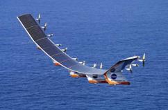
Figure 2. AeroVironment Helios [6]
Helios has reached an altitude as high as 96,863 feet and sustained more than 40 minutes of flight tests at altitudes higher than 96,000 feet (NASA, Helios, n.d.). The 75.3 m wingspan contributes an aspect ratio of 30.9 to 1. The long slender wing provides a good reference for wing design with its shape. It is worth noting that Helios is also a solar-powered aircraft with its solar panels mounted on the top surface of the wing. This coincides with the common practice of using solar power for spacecraft due to its availability. For the aircraft of identical mass on Mars, the lift is only required to be one-third as on Earth due to lower gravitational force, hence the wing size can be reduced compared to its counterparts on Earth.
After all, with the support of theory and examples for reference in designing, it is clear that such mission design is viable for an aircraft to maintain a powered flight in Mars atmosphere operating as a fixed-wing aircraft with optimised aerodynamic characteristics for the given atmospherical condition.
4. Aircraft design – Propulsion
While ARES utilises a bi-propellant rocket system for its mission, the aircraft design in this research aims to be capable of being reused for flights with a much longer mission duration. For such requirements, an Electric propulsion system is advantageous over rocket propellants in terms of reusability and availability of regenerating energy by utilising solar power. An electric propulsion system powering an aircraft consists of an array of batteries, a digital controller, a motor, a gearbox and a propeller. The propeller is designed to have a larger size compared to aircraft on Earth due to the lower air density on Mars. The simplicity of such a system reduces points of possible failure and reduces mass of mechanical parts of the aircraft.
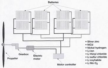
Figure 3. Battery-powered system layout [7].
As shown by the configuration in Figure 3, a major concern of an electric-powered aircraft is the mass of the battery. Spacecrafts are designed with the least mass possible. The constraint of using batteries on aircraft in research is the energy density. As the energy density of the battery is constantly improving over the years, the aircraft should eventually be able to achieve a considerable range with batteries generated entirely from solar power. However, if considered for technical readiness as well as extending the range of aircraft on each flight, the fuel cell can also be considered. Several spacecraft were hindered by the decline of power regeneration rate issues due to Mars dust covering their solar panels. A common solution to the issue is by utilising MMRTG (Multi-Mission Radioisotope Thermoelectric Generator) to generate electricity, such as on Mars rover Curiosity and Perseverance. For Mars aircraft, such an issue can be solved with more ease as wind can blow off most of the dust covering the surface of the solar panel. The omission of MMRTG saves a precious mass of the aircraft as well as reduces the cost of the mission.
DEP (Distributed Electric Propulsion) is proposed for use on this aircraft to reduce energy consumption in flight. The idea of DEP is that an aircraft requires most power when taking off, but only requires a fraction of take-off power to maintain cruise. By installing numerous small electric motors on the aircraft and operating them only in take-off, the aircraft gains considerable efficiency in cruise by turning off redundant motors. NASA’s X-57 Maxwell experimental aircraft utilizes DEP technology to demonstrate its edge on energy efficiency. The aircraft is designed to gain an aero-propulsive efficiency of 3.5 by utilising its 12 in-board high-lift electric motor/propeller propulsors as shown in Figure 4 [8].
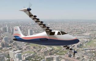
Figure 4. NASA X-57 Maxwell [8]
By utilising DEP technology on the aircraft, the aircraft can be able to maintain a low power consumption in cruise flight while ensuring enough take-off performance. This is beneficial for mass reduction of the aircraft due to the issue of battery energy density, as stated above. Several smaller motor/propeller combinations also contribute to the redundancy of the propulsion system, which is an important design requirement for spacecraft as they are usually not available for maintenance or repair.
5. Aircraft design – Tilt-wing
Tilt-wing is a wing design combining the advantages of rotorcrafts with fixed-wing aircraft. When taking off, the aircraft uses thrust generated by its engine entirely to lift itself. After gaining enough altitude, the aircraft flies forward and the wing gradually rotates level. When the wing is fully level, the aircraft operates with the same principle as fixed-wing aircraft. This design ensures the VTOL (Vertical Take-Off and Landing) capability of the aircraft but also gifts the aircraft with higher cruising speed and better energy efficiency compared to other rotorcrafts. On Mars, VTOL capability is crucial because of its rough terrain. Taking off on Mars Surface with a certain distance can lead to a significant risk of hitting obstacles and terrain, damaging the aircraft. In cruise flight, fixed-wing aircraft offer superior efficiency and flight speed performance compared to rotorcrafts. These two features help save the mass of the battery as well as extend the range of the aircraft. These features help with more versatility for scientific applications in surface surveying and gas sampling. NASA Langley Centre has developed the concept of electric tilt-wing aircraft for future applications on eVTOL (electric Vertical Take-Off and Landing) aircraft and has conducted successful test flights with scale-down models, proving the viability of the concept [9]. The Langley Aerodrome No. 8 (LA08), shown in Figure 5, has successfully conducted flight tests involving vertical take-off and landing as well as cruise flight with wings tilted level.
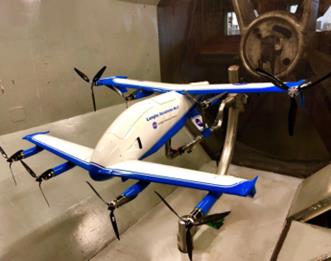
Figure 5. Langley Aerodrome No. 8 (LA-8) electric VTOL [9]
The mechanism of the tilt-wing structure also increases the complexity of the spacecraft as well as adding to possible failure points. However, with the efficiency contributed by DEP as well as wing-generating lift, the capability aircraft gain from this design outweighs its risks and costs.
6. Launch Vehicle Selection and Constraints
For a spacecraft to be deployed onto Mars, it must be launched from Earth on a launch vehicle first. It then needs to cruise on a course towards Mars and eventually survive the entry into Mars atmosphere. This poses potential constraints to the design of Martian aircraft, both in terms of mass and size.
The ARES aircraft is aimed at having a wet mass (spacecraft plus the propellant) under 175 kilograms and launching towards Mars on a Delta II 7925 rocket, which eventually delivered 670-kilogram Phoenix Lander for the Mars scout mission. At present, the mass of spacecraft delivered to Mars has been drastically higher. The Mars 2020 mission was launched on an Atlas V 541 rocket, which can transport 3649 kilograms of mass towards Mars in this mission. With the presence of Falcon Heavy, a potential of 16800 kilograms can be delivered to Mars at a reasonable cost. Hence the Martian aircraft has a better margin in terms of mass allocation. However, the size of the spacecraft rocket can accommodate is limited as well. Given the high aspect ratio of the wing, the wing would have to be folded to fit the large wingspan into faring of the rocket. The diameter of an Ariane 6 rocket has a maximum of 4700 millimeter inside (shown in Figure 6). This poses a challenge to the design of the packaging of the spacecraft. The aircraft and its landing platform would need to be packed into the fairing with a heat shield to sustain heat in Mars atmosphere entry as well as a service module to provide electricity and attitude control in space.
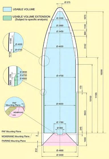
Figure 6. Inside fairing dimension of Ariane 6 rocket ©Arianespace
For the aircraft to conduct repeated flights, the aircraft is not designed to be released in mid-air after reentry but carried on a platform with propulsion system for landing. The aircraft can then take off from the platform after charging its battery fully. Hence the size of landing platform is constrained to the maximum available size inside the fairing of its launch vehicle.
7. Conclusion
The development of an electric tilt-wing Martian aircraft has been described above with a systematic approach towards its design specifications. Solutions are provided to address problems and risks that arise with the designing process. Overall, the Martian aircraft design possesses several technical features that are newly developed and can lead to a performance advantage over its predecessor and counterparts. However, the design is not without technical difficulties, hence more empirical research into the concept may still be required in the future as the scope of this research did not involve any prototyping or testing. Further developments may involve testing aircraft equipped with both tilt-wing and DEP features in high altitudes to simulate atmospheric conditions on Mars as well as testing the reliability of hardware in extreme temperatures. Integrating flight control software for the aircraft, which is another major technical challenge for the aircraft, with the hardware is also another key milestone required to be achieved for the aircraft to find its way to utilisation.
References
[1]. H. S. W. M. A. C. J. S. L. D. A. S. Robert D. Braun, “Design of the ARES Mars Airplane and Mission Architecture,” 2006.
[2]. N. S. S. D. C. Archive, “Mars Fact Sheet - the NSSDCA,” December 2023. [Online]. Available: https://nssdc.gsfc.nasa.gov/planetary/factsheet/marsfact.html.
[3]. NASA, “Air Mass/Density - Earthdata - NASA,” October 2019. [Online]. Available: https://www.earthdata.nasa.gov/topics/atmosphere/atmospheric-pressure/air-mass-density.
[4]. NASA, “Induced Drag Coefficient,” July 2023. [Online]. Available: https://www.grc.nasa.gov/www/k-12/VirtualAero/BottleRocket/airplane/induced.html.
[5]. G. L. a. V. L. Anthony Colozza, “Overview of Innovative Aircraft Power and Propulsion Systems and Their Applications for Planetary Exploration,” NASA, 2003.
[6]. NASA, “Helios,” [Online]. Available: https://www.nasa.gov/image-article/helios/.
[7]. P. M. R. K. P. A. S. a. T. F. Sean Clarke, “X-57 Power and Command System Design,” 2017.
[8]. R. C. B. a. G. H. David D. North, “Design and Fabrication of the Langley Aerodrome No. 8 Distributed Electric Propulsion VTOL Testbed,” 2020.
[9]. Arianespace, ARIANE 6 USER’S MANUAL, 2021.
Cite this article
He,Z. (2024). Design of an electric tilt-wing Martian aircraft. Applied and Computational Engineering,66,79-86.
Data availability
The datasets used and/or analyzed during the current study will be available from the authors upon reasonable request.
Disclaimer/Publisher's Note
The statements, opinions and data contained in all publications are solely those of the individual author(s) and contributor(s) and not of EWA Publishing and/or the editor(s). EWA Publishing and/or the editor(s) disclaim responsibility for any injury to people or property resulting from any ideas, methods, instructions or products referred to in the content.
About volume
Volume title: Proceedings of the 2nd International Conference on Functional Materials and Civil Engineering
© 2024 by the author(s). Licensee EWA Publishing, Oxford, UK. This article is an open access article distributed under the terms and
conditions of the Creative Commons Attribution (CC BY) license. Authors who
publish this series agree to the following terms:
1. Authors retain copyright and grant the series right of first publication with the work simultaneously licensed under a Creative Commons
Attribution License that allows others to share the work with an acknowledgment of the work's authorship and initial publication in this
series.
2. Authors are able to enter into separate, additional contractual arrangements for the non-exclusive distribution of the series's published
version of the work (e.g., post it to an institutional repository or publish it in a book), with an acknowledgment of its initial
publication in this series.
3. Authors are permitted and encouraged to post their work online (e.g., in institutional repositories or on their website) prior to and
during the submission process, as it can lead to productive exchanges, as well as earlier and greater citation of published work (See
Open access policy for details).
References
[1]. H. S. W. M. A. C. J. S. L. D. A. S. Robert D. Braun, “Design of the ARES Mars Airplane and Mission Architecture,” 2006.
[2]. N. S. S. D. C. Archive, “Mars Fact Sheet - the NSSDCA,” December 2023. [Online]. Available: https://nssdc.gsfc.nasa.gov/planetary/factsheet/marsfact.html.
[3]. NASA, “Air Mass/Density - Earthdata - NASA,” October 2019. [Online]. Available: https://www.earthdata.nasa.gov/topics/atmosphere/atmospheric-pressure/air-mass-density.
[4]. NASA, “Induced Drag Coefficient,” July 2023. [Online]. Available: https://www.grc.nasa.gov/www/k-12/VirtualAero/BottleRocket/airplane/induced.html.
[5]. G. L. a. V. L. Anthony Colozza, “Overview of Innovative Aircraft Power and Propulsion Systems and Their Applications for Planetary Exploration,” NASA, 2003.
[6]. NASA, “Helios,” [Online]. Available: https://www.nasa.gov/image-article/helios/.
[7]. P. M. R. K. P. A. S. a. T. F. Sean Clarke, “X-57 Power and Command System Design,” 2017.
[8]. R. C. B. a. G. H. David D. North, “Design and Fabrication of the Langley Aerodrome No. 8 Distributed Electric Propulsion VTOL Testbed,” 2020.
[9]. Arianespace, ARIANE 6 USER’S MANUAL, 2021.