


1. Introduction
Multiple drawing passes will cause one or more large deformations of the blank, which will lead to different degrees of changes in the mechanical properties and thickness uniformity of the material, so it is difficult to predict the formability of the part through previous experience. After decades of development, the finite element method has been gradually applied to the simulation of various complex parts, and the reliability and accuracy of its analyses have gradually been consistent with the actual production[1] . This paper focuses on the numerical simulation and empirical design analysis of the multi-pass deep drawing process for thin-walled hollow cylindrical parts made of H68 material. The objective is to investigate the impact of factors such as material properties, process parameters, and mold parameters. By optimizing the mold structure, we aim to design an effective multi-pass deep drawing process. The findings of this study serve as a valuable reference for the practical production of similar parts.
The thin-walled hollow cylindrical parts depicted in Figure 1 possess small overall dimensions with a thickness of merely 0.4 mm. Despite their general accuracy requirements, these parts exhibit a large diameter ratio of 1.5, classifying them as small deep-drawing cylindrical parts [2]. The calculated results indicate a total depth of pull coefficient, m, of approximately 0.33, which is 0.15 lower than the maximum depth of pull coefficient allowed by the material (0.48). Thus, to achieve improved forming quality, multiple deep-drawing operations are necessary for the formation of these thin-walled hollow cylindrical parts. Consequently, in the production process of such parts, the rational allocation of deep-drawing coefficients and the design of the mold structure become crucial considerations.
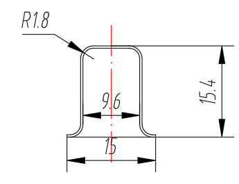
Figure 1. Thin-walled hollow cylinder parts drawing
2. Analysis of the deep drawing and forming process
Deep drawing process is a large deflection, large deformation and complex plastic deformation process, analyse the stress-strain state of each part of the material in the deep drawing process, summarize the stress-strain law, to provide theoretical support for solving the various problems arising in the deep drawing process[3] . Through the deformation analysis of the cylindrical parts, as shown in Figure 2, the material of the cylindrical parts will gradually converge to the cavity of the concave model under the action of the convex mould in the deep-drawing process, resulting in the deformation of the cylindrical parts from the bottom of the cylindrical parts to the position of the flange gradually increasing, so when the blanks are in different positions, the stress-strain state of the blanks in different positions[4] .
(a) Stress-strain diagram during stretching |
(b) Stress distribution during tensile process |
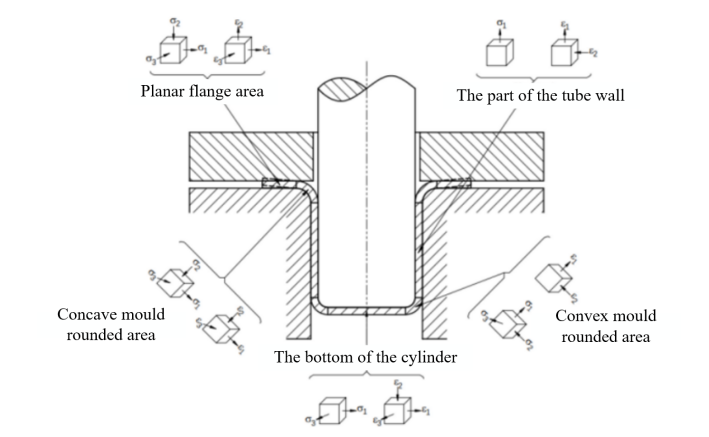
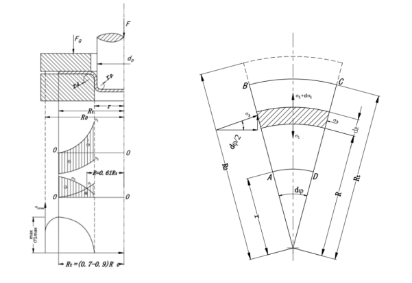
Figure 2. Deformation analysis of cylindrical parts
The trial material is H68 brass in soft state, and its properties are shown in Table 1. By the material in the deep drawing process shows anisotropy, and its mechanical properties have a great influence on the forming quality of the cylindrical parts, so in order to avoid the anisotropy as well as the unevenness or burr around the flange of the thin-walled hollow cylindrical parts caused by uneven mould clearance, plate thickness variation and inaccurate positioning, usually trimming treatment is also required after deep drawing and forming[5] . According to the relevant data, the trimming allowance of the cylindrical part is 1.6mm, and the diameter of the blank is calculated to be 30.1mm.
Table 1. Properties of H68 brass
Density/(kg \( ∙ \) m-3) | Modulus of elasticity/ GPa | Poisson’s ratio | Yield strength/MPa | Tensile strength/MPa |
8.80 | 110 | 0.34 | 100 | 370 |
Compared with single-pass deep-drawing, the forming mechanism of multi-pass deep-drawing is more complicated, and each pass affects each other and cannot be studied independently. In addition, there is work hardening phenomenon in multi-pass deep-drawing, and reasonable distribution of the ratio of deep-drawing in each pass to make the deformation as uniform as possible is the key to its success. At the same time, each forming should avoid the local deformation is too large and exceeds the forming limit, otherwise it will cause serious hardening phenomenon in the latter deep-drawing, which can’t carry out the subsequent deep-drawing, resulting in the parts being cracked and damaged[6] . According to the empirical formula can be calculated for each deep-drawing coefficient: m1 for 0.42 ~ 0.51, m2 for 0.67 ~ 0.69, m3 for 0.7 ~ 0.72, i.e., the part needs to be deep-drawn at least three times. Preliminary determination of each deep-drawing convex and concave die corner radius: Rp = 2mm, Rc = 2mm. So, the depth of each deep-drawing: h1 = 11.18mm, h2 = 13.13mm, h3 = 15mm. At the same time, the multi-drawing of thin-walled hollow cylindrical parts forming mould is mainly composed of crimping ring, punches, concave die and other parts, and the first to the third need to be used in crimping ring to prevent the parts lost in the deep-drawing process, and the first to the third need to use crimping ring. The mould is mainly composed of crimping ring, punch, concave mould and other parts.
3. Numerical analysis of multi-pass deepening
The deformation of the sheet metal is derived from the external work of the press acting on the punch, which is transferred by the contact friction between the mould and the sheet metal. Therefore, the theory and accuracy of the CAE software contact algorithm often directly determine the reliability of the analysis[7] . The finite element simulation used in this paper is done in Dynaform, and its design steps are shown in Figure 3.
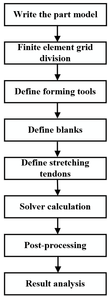
Figure 3. Generic steps for sheet forming
The geometric model was built in Creo software, and then imported into Dynaform software for parameter setting. First of all, the tool body definition of the model and mesh division of the blank, choose H68 material, the friction coefficient is calculated according to the default value, set the forming speed of 10mm/s, the friction coefficient of the convex die is 0.4, the friction coefficient of the concave die is 0.1, and the crimping force is 500 N. When simulating the deep drawing process, according to the crimping circle downward movement and the punch downward movement of the two different motion processes, which can be divided into two (The crimping ring is responsible for providing the crimping force to hold down the blank; the movement of the punch can drive the blank to form, ensuring that the crimping force remains constant throughout the process). The results obtained in the first deep drawing are shown in Figure 4, and the forming effect is good.
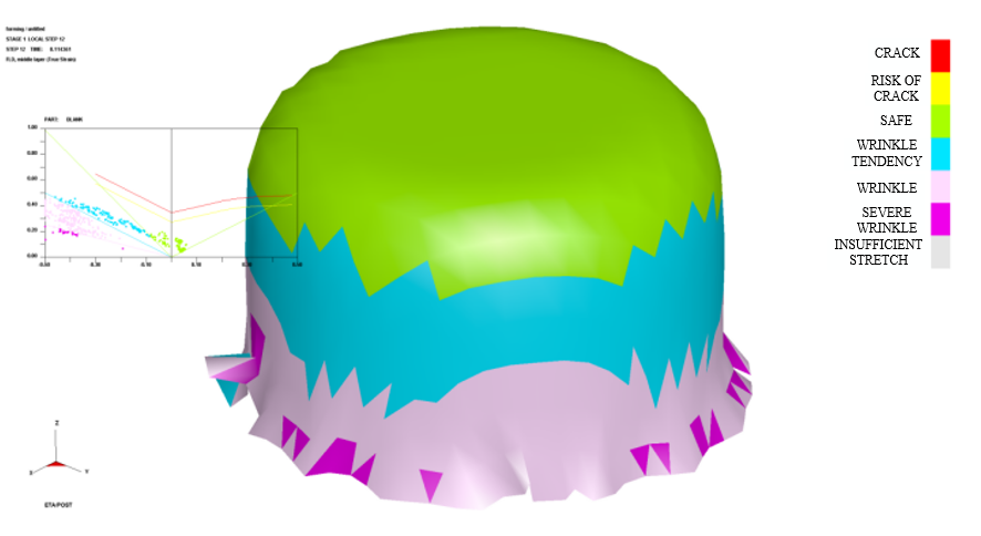
Figure 4. First forming result
As can be seen from the analysis results, the billet deformation is within the safe range, and there is no cracking and cracking trend in the first deep drawing. However, the cold hardening phenomenon will occur in the forming process of H68 brass sheet, so the subsequent forming simulation must take into account the differences in material properties when forming at different locations. Using the above procedure to continue to add the next process, the simulation results of the second deep drawing are obtained as shown in Figure 5.
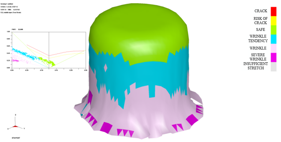
Figure 5. Second forming result
The simulation results show that from the 3rd pass onwards, the spacing between the crimping ring and the blank has a great influence on the forming process of the cylindrical parts. Simulation results show that if the distance between the crimp ring and the blank is greater than 0.4 mm, it will lead to serious instability in the deep drawing process, and if the distance between the crimp ring and the blank is too small, it will not be able to give full play to the role of the crimp ring. Through repeated adjustment of the gap size after comparison and analysis, it was found that the gap between the crimping ring and the blank between 0.1 ~ 0.3mm, the thin-walled hollow cylindrical parts of the forming effect is better, as shown in Figure 6. For the convenience of practical operation, the gap between the crimping ring and the convex mould is taken as 0.3mm for the 2nd and 3rd passes.
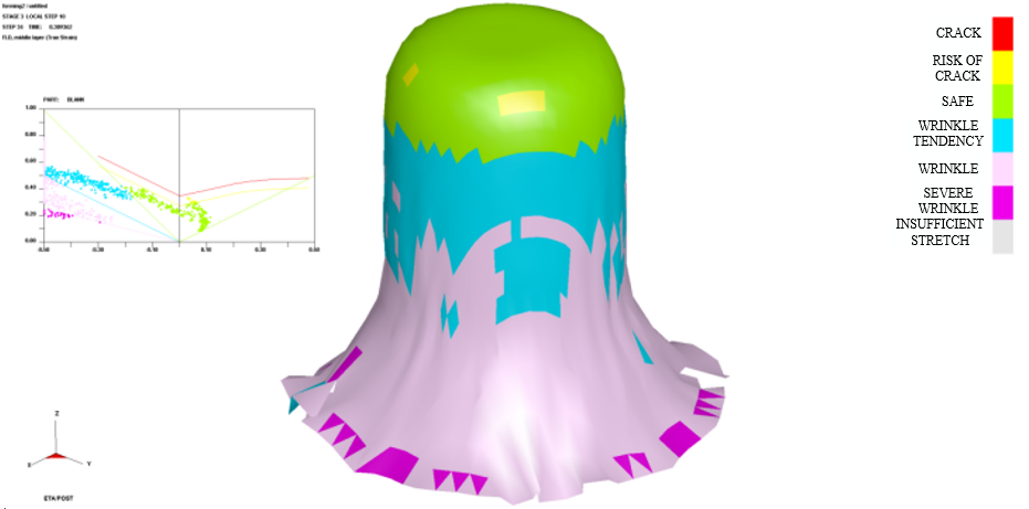
Figure 6. Third forming result
4. Mould design and process analysis
Different mould parameters and processes in the actual production process of deep drawing parts forming quality, deep drawing cost, mould adjustment cycle has an important impact, its reasonableness can not only improve the uniformity of deep drawing forming can also reduce the high demands on the material, greatly reducing the cost of deep drawing and reducing the time of mould adjustment[8~10] . In the actual production of convex-concave die radius, material thickness, crimping force, stamping speed and other process parameters have a greater impact on the forming quality of deep-drawing parts, while the development of new moulds itself has a longer debugging cycle, and mould parameters and process parameters are interrelated, so in the design and development must be reasonable formulation of mould parameters and process parameters, otherwise it will greatly extend the cycle of mould adjustment or even lead to the scrapping of the mould.
The 600kN hydraulic press was chosen for this deep drawing trial. Through the Dynaform simulation analysis, it can be seen that in the deep drawing process, because the deformation of the raw material is very little, so the 1st deep drawing is relatively easy to carry out, but it puts forward higher requirements on the positioning accuracy of the blank, if the positioning is not accurate, there will be eccentricity, which affects the quality of the subsequent forming. In addition, in order to prevent the bottom of the cylinder from pulling apart during the 2nd and 3rd deep drawing passes, a limit block was added to the mould to restrain it, as shown in Figure 7.
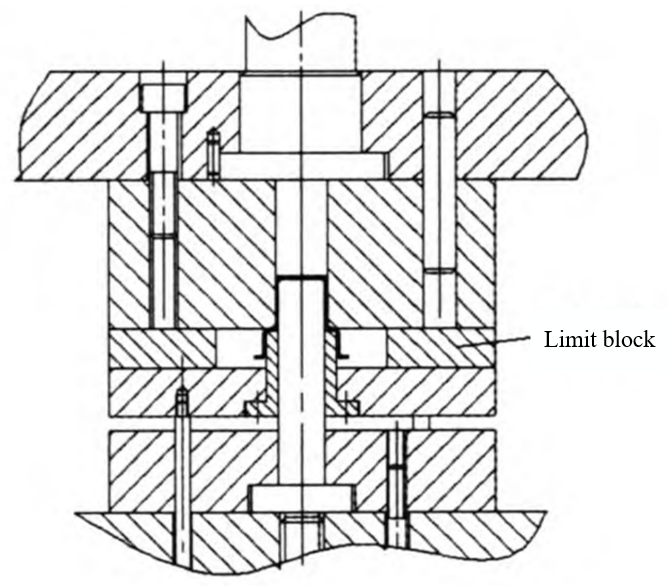
Figure 7. Limit block structure of tension mould
After comparing the influence of each process parameter on the forming quality, the following conclusion can be drawn: The forming quality of the workpiece is significantly affected by the radius of the convex and concave die circle angles. When the radius of the convex die circle angle is either too large or too small, the forming quality of the workpiece is severely compromised, resulting in pulling cracks, wrinkles, and other serious issues [11]. Similarly, when the concave die radius is too small, the flow of the metal material during deep drawing becomes difficult, leading to ruptures. On the other hand, when the concave die radius is too large, the blank prematurely exits the crimp ring, resulting in wrinkling. The maximum thinning rate of the workpiece varies with changes in the crimping force. When the crimping force exceeds the theoretical value, the increase in thinning rate becomes evident, causing severe thinning and cracking in the bottom corner transition zone. The stamping speed also has a significant impact on the deep drawing parts. If the stamping speed is too high, the bottom of the deep drawing part may crack directly. Conversely, if the stamping speed is too low, severe wrinkling occurs at the top of the part, leading to compression instability.
5. Conclusion
By employing a combination of Dynaform finite element simulation analysis and practical production experience, this study conducted the design and optimization of multi-drawing processes and molds for thin-walled hollow cylindrical parts. The investigation also analyzed the influence of material, process, and key mold parameters on the deep-drawing process. The findings provide an improvement plan for enterprises engaged in the design and development of deep-drawing molds and the optimization of deep-drawing process parameters. Moreover, they offer effective and scientifically grounded theoretical guidance.
Following numerous debugging iterations, the optimization of the thin-walled hollow cylindrical parts encompassed adjustments to parameters such as blank size, number of deep-drawing stages, and process parameters. Concurrently, modifications were made to the mold structure to enhance the deep-drawing forming process. Based on these enhancements, an optimized multi-stage deep-drawing process and mold program were developed for thin-walled hollow cylindrical parts. This program successfully improved the dimensional accuracy and appearance quality of the deep-drawn parts, reduced production costs, facilitated lightweight manufacturing, and ultimately ensured the production of qualified thin-walled hollow cylindrical parts.
References
[1]. FAN Xiaobo,KONG Fanyu,WANG Xugang et al.Wrinkling law of deep drawing forming of ST16 thin-walled curved parts[J]. Journal of Plasticity Engineering,2023,30(02):34-40.
[2]. LIU Xin, GUO Muji, LI Denghu et al. Analysis of deep drawing forming process and mould design of cartridge case[J]. Forging Technology,2022,47(12):81-86.
[3]. Wu Lijun. Research on friction mechanism and hydraulic pulsation lubrication process of deep drawing forming of cylindrical parts[D]. Yanshan University,2022.
[4]. WANG Shiheng,LI Gui,HE Xinxin. Influence of mould surface texture on deep drawing and forming performance of cylindrical parts[J]. Forging Technology,2022,47(02):42-48.
[5]. Cheng Bo. Numerical simulation study on forming process of automotive deep drawing cylindrical parts[J]. Automotive Technologist,2021(09):42-45.
[6]. REN Guangyi,WANG Xiaokang,HE Wanfei et al. Analysis and numerical simulation of multi-drawing forming process of second-order cylindrical parts[J]. Mould Industry,2021,47(02):32-35.
[7]. QIU Jiantong,DENG Peiran,SHAO Wei et al. Deep drawing forming of aluminium alloy cylindrical parts based on Dynaform[J]. Forging Technology,2020,45(05):49-55.
[8]. Li Chao. Research on deep drawing forming process and quality control of 3104 aluminium alloy thin-walled high rectangular parts [D]. South China University of Technology,2020.
[9]. SUN Wen,TIAN Wenchun,JI Xiaohu et al. Influence of process parameters on the deep drawing of cylindrical battery shells[J]. Forging and Stamping,2022(20):23-26.
[10]. ZHANG Zheng, YU Zhangyong, ZHANG Hu. Numerical simulation of the preferred configuration of multi-pass deep-drawing intermediate[J]. Mechanical Design and Manufacturing,2022(04):200-203.
[11]. XIAO Bing’e, WEN Tong, YU Jianming. Multi-pass deep drawing process and mould design for H68 copper bushings with large height-to-diameter ratio[J]. Thermal Processing Technology,2013,42(09):87-89.
Cite this article
Xie,H.;Lu,Y.;Li,R.;Liu,J. (2024). Multi-pass deep-drawing process and mould design for thin-walled hollow cylindrical parts. Applied and Computational Engineering,70,85-91.
Data availability
The datasets used and/or analyzed during the current study will be available from the authors upon reasonable request.
Disclaimer/Publisher's Note
The statements, opinions and data contained in all publications are solely those of the individual author(s) and contributor(s) and not of EWA Publishing and/or the editor(s). EWA Publishing and/or the editor(s) disclaim responsibility for any injury to people or property resulting from any ideas, methods, instructions or products referred to in the content.
About volume
Volume title: Proceedings of the 2nd International Conference on Functional Materials and Civil Engineering
© 2024 by the author(s). Licensee EWA Publishing, Oxford, UK. This article is an open access article distributed under the terms and
conditions of the Creative Commons Attribution (CC BY) license. Authors who
publish this series agree to the following terms:
1. Authors retain copyright and grant the series right of first publication with the work simultaneously licensed under a Creative Commons
Attribution License that allows others to share the work with an acknowledgment of the work's authorship and initial publication in this
series.
2. Authors are able to enter into separate, additional contractual arrangements for the non-exclusive distribution of the series's published
version of the work (e.g., post it to an institutional repository or publish it in a book), with an acknowledgment of its initial
publication in this series.
3. Authors are permitted and encouraged to post their work online (e.g., in institutional repositories or on their website) prior to and
during the submission process, as it can lead to productive exchanges, as well as earlier and greater citation of published work (See
Open access policy for details).
References
[1]. FAN Xiaobo,KONG Fanyu,WANG Xugang et al.Wrinkling law of deep drawing forming of ST16 thin-walled curved parts[J]. Journal of Plasticity Engineering,2023,30(02):34-40.
[2]. LIU Xin, GUO Muji, LI Denghu et al. Analysis of deep drawing forming process and mould design of cartridge case[J]. Forging Technology,2022,47(12):81-86.
[3]. Wu Lijun. Research on friction mechanism and hydraulic pulsation lubrication process of deep drawing forming of cylindrical parts[D]. Yanshan University,2022.
[4]. WANG Shiheng,LI Gui,HE Xinxin. Influence of mould surface texture on deep drawing and forming performance of cylindrical parts[J]. Forging Technology,2022,47(02):42-48.
[5]. Cheng Bo. Numerical simulation study on forming process of automotive deep drawing cylindrical parts[J]. Automotive Technologist,2021(09):42-45.
[6]. REN Guangyi,WANG Xiaokang,HE Wanfei et al. Analysis and numerical simulation of multi-drawing forming process of second-order cylindrical parts[J]. Mould Industry,2021,47(02):32-35.
[7]. QIU Jiantong,DENG Peiran,SHAO Wei et al. Deep drawing forming of aluminium alloy cylindrical parts based on Dynaform[J]. Forging Technology,2020,45(05):49-55.
[8]. Li Chao. Research on deep drawing forming process and quality control of 3104 aluminium alloy thin-walled high rectangular parts [D]. South China University of Technology,2020.
[9]. SUN Wen,TIAN Wenchun,JI Xiaohu et al. Influence of process parameters on the deep drawing of cylindrical battery shells[J]. Forging and Stamping,2022(20):23-26.
[10]. ZHANG Zheng, YU Zhangyong, ZHANG Hu. Numerical simulation of the preferred configuration of multi-pass deep-drawing intermediate[J]. Mechanical Design and Manufacturing,2022(04):200-203.
[11]. XIAO Bing’e, WEN Tong, YU Jianming. Multi-pass deep drawing process and mould design for H68 copper bushings with large height-to-diameter ratio[J]. Thermal Processing Technology,2013,42(09):87-89.